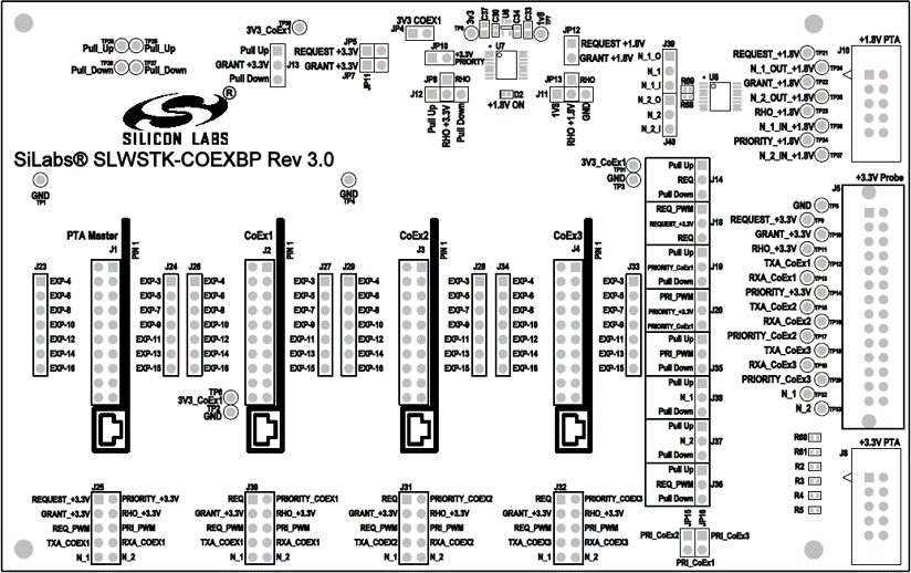
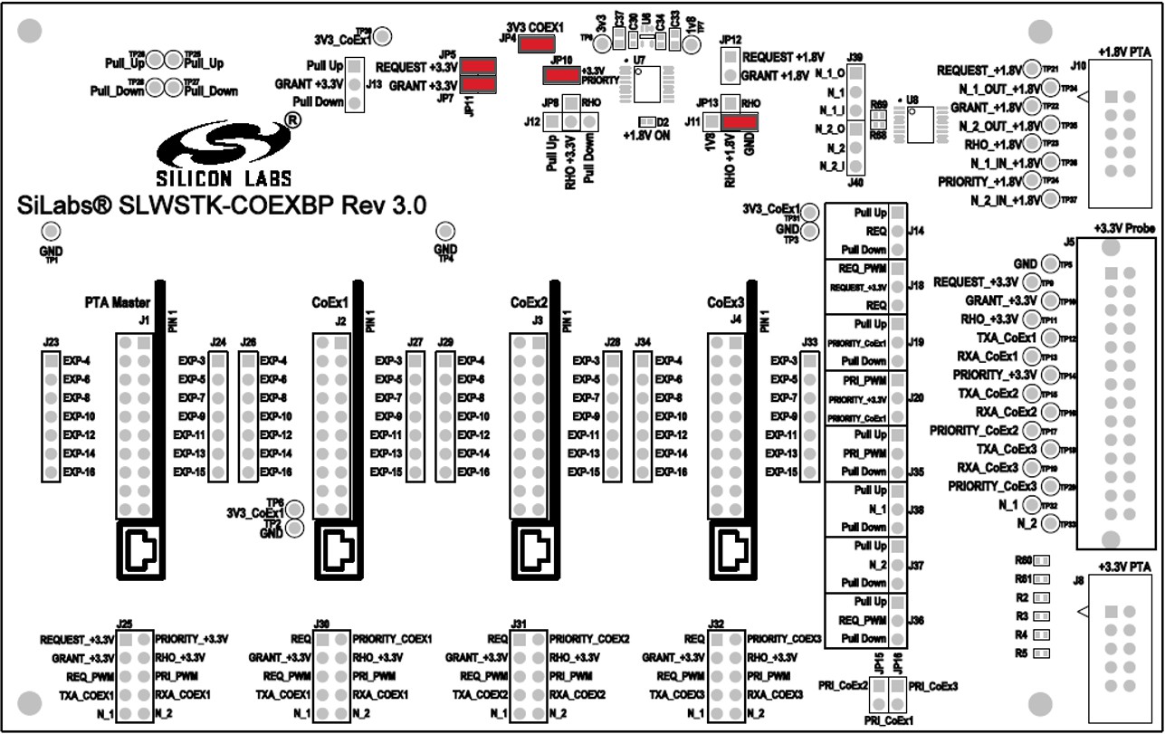
Coexistence Backplane Board#
This page gives a detailed explanation of the Coexistence Backplane Board. The board is compatible with all EFR32MG1x series devices. The "Jumper Wire Recommendations for PTA on Different Devices" table, below, shows recommended PTA pin selections for different supported boards.
Note: Due to GPIO limitations on some boards, GPIOs routed to peripherals on the WSTK may need to be used for PTA functions. This requires disabling the default peripheral configurations in the Hardware Configurator. Instructions on how to achieve this are in section Disabling Peripheral Functionality.
For BRD4169: Button and LED peripherals must be disabled.
For BRD4180: Button, LED, and UART RTS/CTS must be disabled. Other radio boards do not require any peripherals to be disabled.
Jumper Wire Configurations for Different Boards/Devices#
Jumper Wire Recommendations for PTA on Different Devices:
Board/Device | REQUEST (EXP/GPIO) | GRANT (EXP/GPIO) | PRIORITY (EXP/GPIO) | RHO (EXP/GPIO) |
|---|---|---|---|---|
BRD4151/EFR32MG1P | EXP15/PC10 | EXP13/PF3 | EXP11/PD12 | EXP16/PC11 |
BRD4161/EFR32MG12P | EXP15/PC10 | EXP13/PC9 | EXP11/PD12 | EXP16/PC11 |
BRD4168/EFR32MG13P | EXP15/PC10 | EXP13/PF3 | EXP11/PD12 | EXP16/PC11 |
BRD4169/EFR32MG14P | EXP15/PC10 | EXP13/PF3 | EXP10/PC9 | EXP16/PC11 |
BRD4180/EFRMG21 | EXP11/PB00 | EXP6/PC01 | EXP13/PB01 | Not supported |
It is also helpful to observe the FEM control signals, and the recommended pins for different boards are shown in the following table.
Jumper Wire Recommendations for Radio State on Different Devices:
Board/Device | TX PRS Channel | TX (EXP/GPIO) | RX PRS Channel | RX (EXP/GPIO) |
|---|---|---|---|---|
BRD4151/EFR32MG1P | CH5 | EXP7/PD10 | CH6 | EXP9/PD11 |
BRD4161/EFR32MG12P | CH5 | EXP7/PD10 | CH6 | EXP9/PD11 |
BRD4168/EFR32MG13P | CH5 | EXP7/PD10 | CH6 | EXP9/PD11 |
BRD4169/EFR32MG14P | CH2 | EXP7/PF6 | CH3 | EXP9/PF7 |
BRD4180/EFRMG21 | CH8 | EXP7/PD02 | CH9 | EXP9/PD03 |
For jumper positions for different coexistence configurations, refer to section COnfiguring for Different PTA SCenarios.
Disabling Peripheral Functionality#
The following instructions explain how to disable default peripheral configurations on the WSTK, to allow GPIOs routed to these peripherals to be used for PTA functions. Customize the examples as described below, then follow the steps in the applicable quick-start guide to build and flash them to your devices.
In SDK 7.0 and higher#
In the Project Configurator, click the SOFTWARE COMPONENTS tab and type 'button' in the search field to locate the btn1 component.
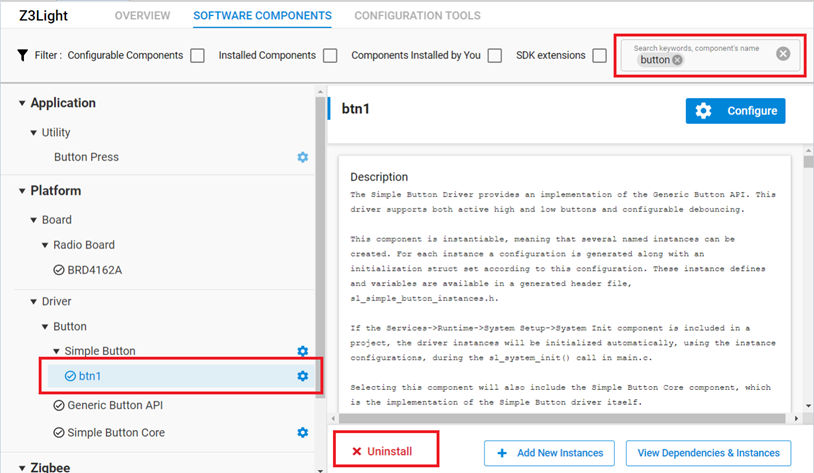
To disable Button peripherals, select the btn1 component and click Uninstall to remove it.
Repeat the process to disable LED peripherals.
Type 'USART' in the search field to locate the vcom component.
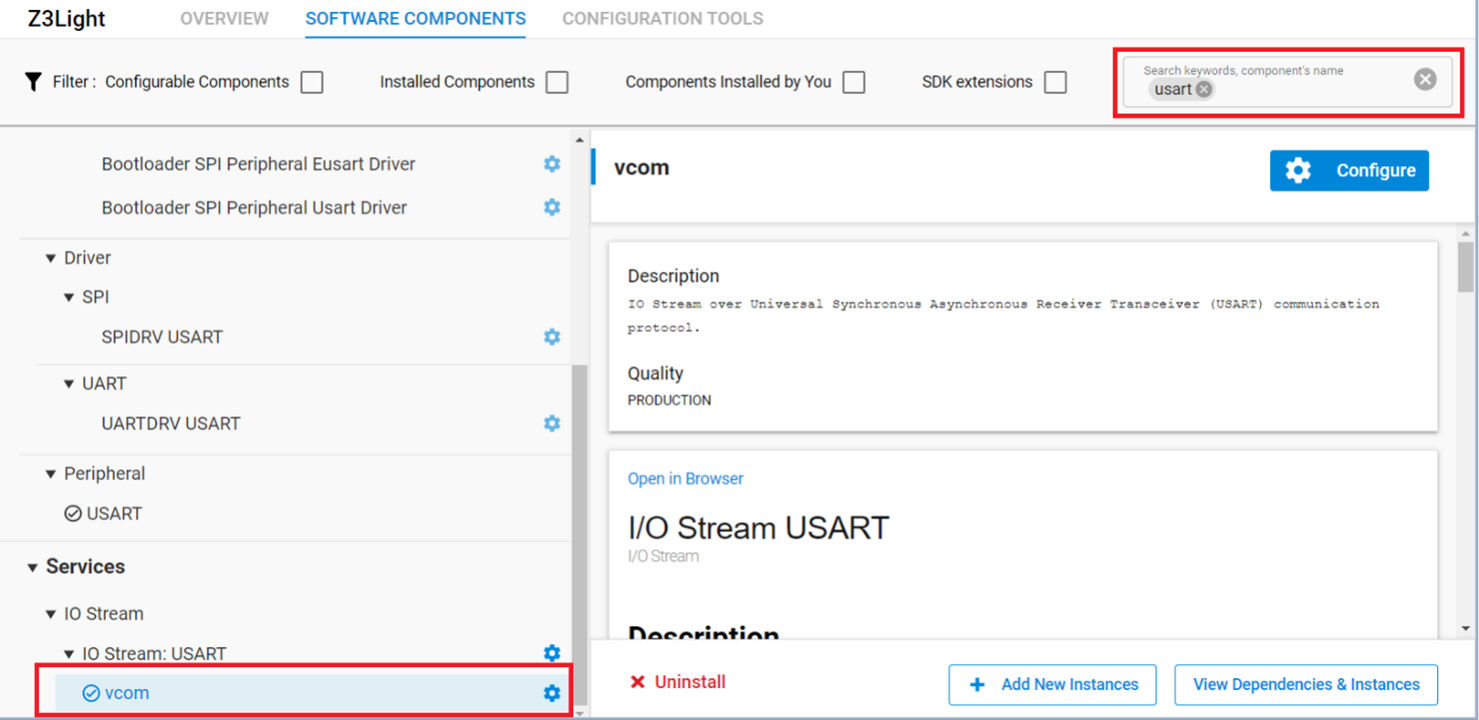
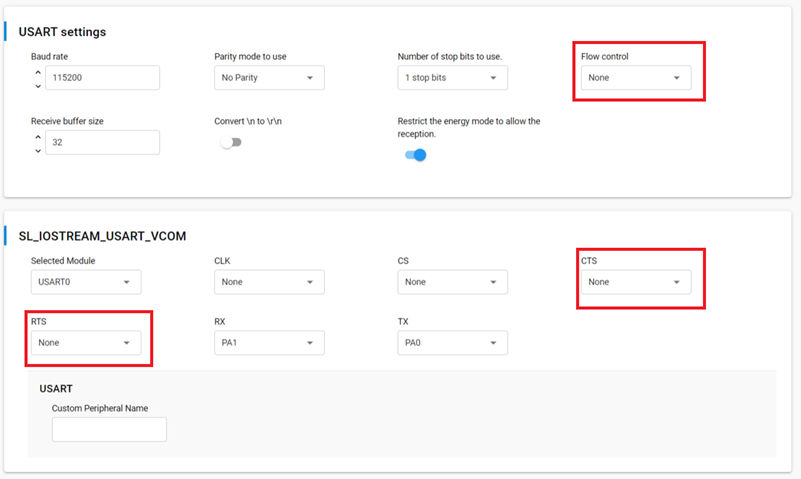
Click Configure to open the Component Editor. To disable the USART CTS/RTS support, change the following settings to None:
FlowControl
CTS
RTS
In SDK 6.10.x and lower#
In the project .isc file, select the HAL configuration tab and click Open Hardware Configurator.
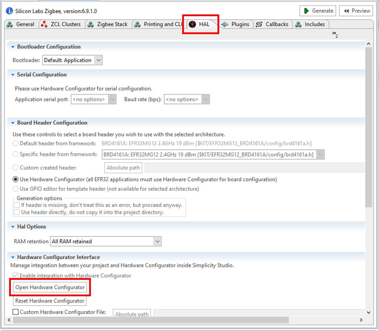
This opens a new tab with the Configurator perspective active.
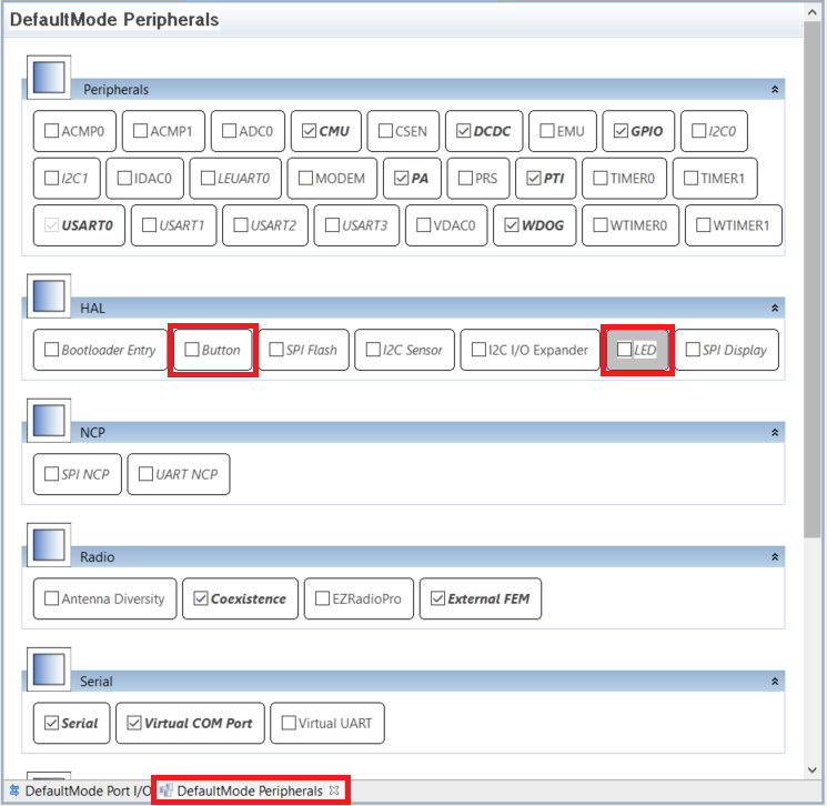
Click the DefaultMode Peripherals tab to open a list of enabled configurators.
To disable LED and Button peripherals, uncheck the checkboxes next to LED and/or Button, and click [Save] (or press Ctrl+S). The hal-config.h file will be automatically updated with the latest changes.
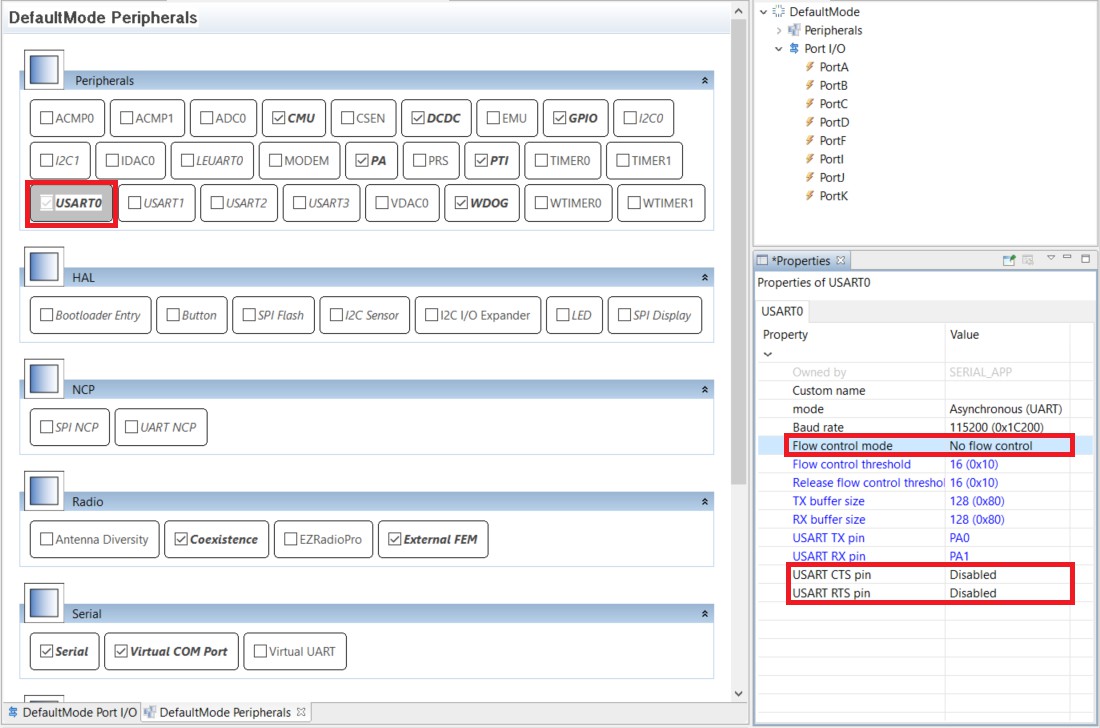
To disable the USART CTS/RTS support, select the USART0 box under Peripherals, and modify the properties as follows:
Flow Control Mode: No flow control
USART CTS pin: Disabled USART RTS pin: Disabled
Click Save (or press Ctrl+S). The hal-config.h file will be automatically updated with the latest changes.
Configuring for Different PTA Scenarios#
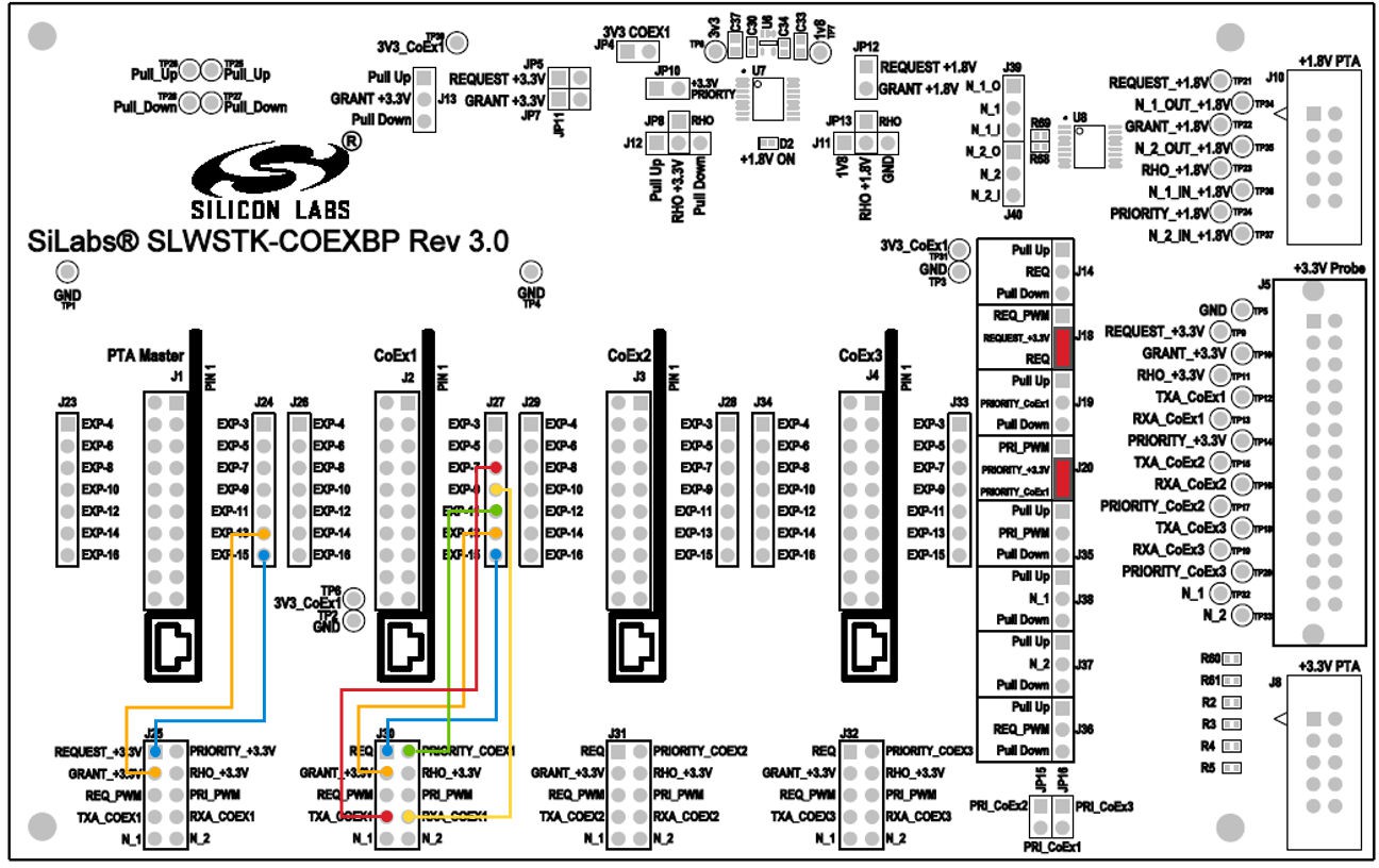
Single-EFR32 Radio#
For a single EFR32 radio, be sure to:
Configure Board jumpers and jumper wires as follows. Make sure the jumper wire selections are based off the board and device being used. Refer to Coexistence Backplane Board for details.
Develop the desired PTA test application using AppBuilder.
Add the coexistence-configuration component/plugin and configure for target Wi-Fi/PTA device as per single-radio description. See PTA Software Setup in Zigbee and OpenThread Coexistence with Wi-Fi.
Add FEM driver component/plugin (configured as described above) to enable TXA and RXA observation.
Build the EFR32 application and program the WSTK.
Plug the EXP header on the EFR32/WSTK Board into Coexistence Backplane Board CoEx1 header (J2) (ensure pin 1 to pin 1).
Enable PTA on the Wi-Fi/PTA device.
Execute Wi-Fi stream and 802.15.4 stream.
Observe Wi-Fi error rate and 802.15.4 message success.
Observe PTA signals to debug and adjust as necessary.
With the PTA solution confirmed, the coexistence-component/plugin only needs to be modified for the PTA GPIOs assigned on target hardware.
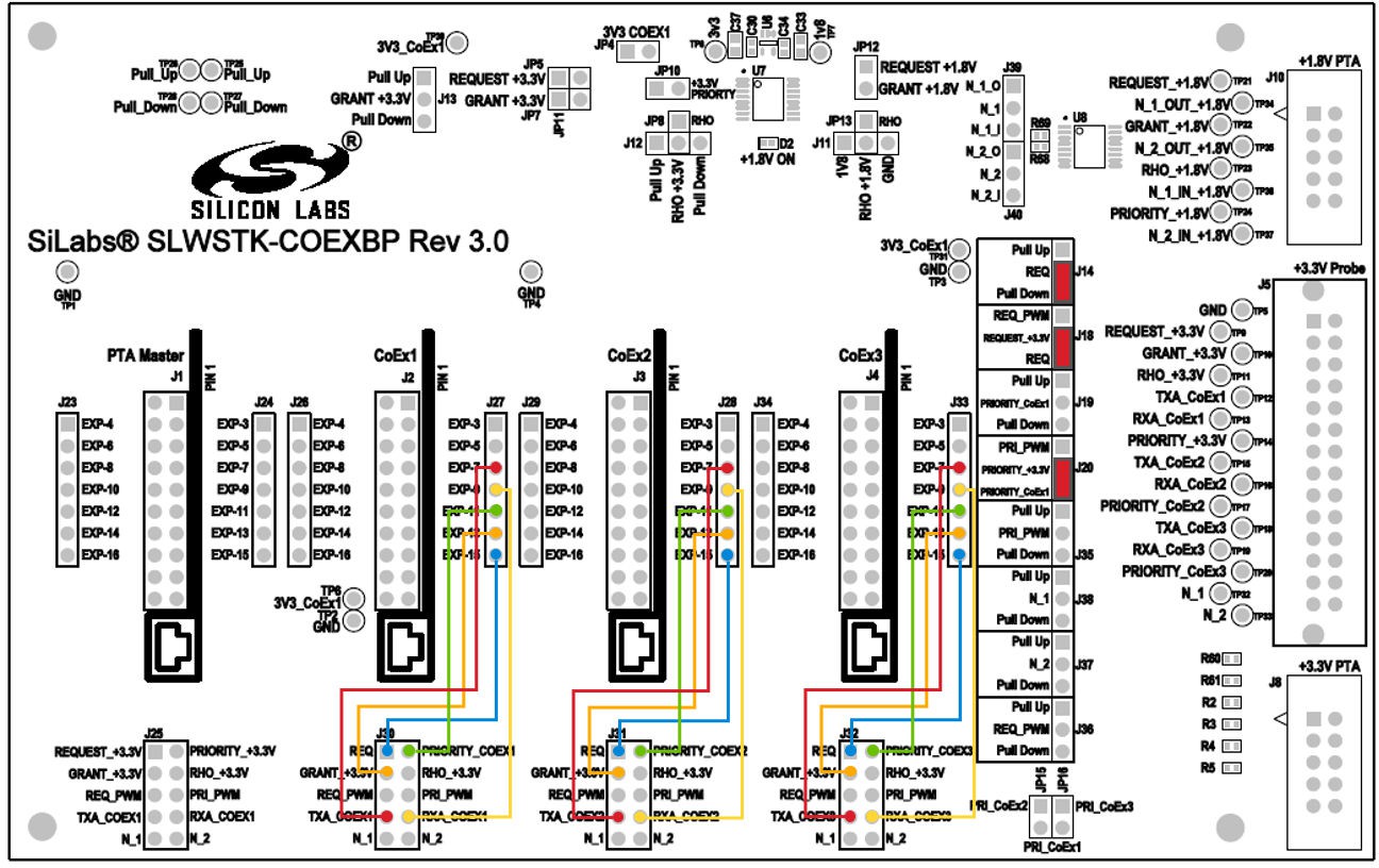
Multi-EFR32 Radios with Unshared PRIORITY
For multi-EFR32 radios with unshared PRIORITY, be sure to do the following:
Configure Board jumpers and jumper wires as follows. If using two radios, do not configure jumper wires for Coex 3. Make sure the jumper wire selections are based off the board and device being used. Refer to Coexistence Backplane Board for details.
Develop the desired PTA test applications in Simplicity Studio.
Add coexistence-configuration components/plugins and configure for target Wi-Fi/PTA device as per multi-radio description. See PTA Software Setup in Zigbee and OpenThread Coexistence with Wi-Fi.
Add the FEM driver component/plugin (configured as described above) to enable TXA and RXA observation.
Build the EFR32 applications and program the WSTKs.
Plug the EXP header on one EFR32/WSTK Board into Coexistence Backplane Board CoEx1 header (J2) and the second and third EFR32/WSTK Boards, if used, into CoEx2 and CoEx3 headers (J3 and/or J4) (ensure pin 1 to pin 1).
Enable PTA on the Wi-Fi/PTA device.
Execute Wi-Fi stream and 802.15.4 streams.
Observe Wi-Fi error rate and 802.15.4 message success.
Observe PTA signals to debug and adjust as necessary.
With the PTA solution confirmed, the coexistence-component/plugin only needs to be modified for the PTA GPIOs assigned on target hardware.
Multi-EFR32 Radios with Shared PRIORITY
For multi-EFR32 radios with shared PRIORITY, be sure to do the following.
Configure Board jumpers and jumper wires as follows. If using 2 radios, do not configure jumper wires for Coex 3. Make sure the jumper wire selections are based off the board and device being used. Refer to Coexistence Backplane Board for details.

Develop desired PTA test applications in Simplicity Studio.
Add coexistence-configuration components/plugins and configure for target Wi-Fi/PTA device as per multi-radio description. See PTA Software Setup in Zigbee and OpenThread Coexistence with Wi-Fi.
Add the FEM driver component/plugin (configured as described above) to enable TXA and RXA observation.
Build the EFR32 applications and program the WSTKs.
Plug the EXP header on one EFR32/WSTK Board into Coexistence Backplane Board CoEx1 header (J2) and the second and third EFR32/WSTK Boards, if used, into CoEx2 and CoEx3 headers (J3 and/or J4) (ensure pin 1 to pin 1).
Enable PTA on the Wi-Fi/PTA device.
Execute Wi-Fi stream and 802.15.4 streams.
Observe Wi-Fi error rate and 802.15.4 message success.
Observe PTA signals to debug and adjust as necessary.
With the PTA solution confirmed, the coexistence-component/plugin only needs to be modified for the PTA GPIOs assigned on target hardware.
PWM Feature#
Refer to Zigbee and OpenThread Coexistence with Wi-Fi on how to set up the board to use the PWM feature.
Signal Identifier Feature (EFR32xG24)#
Refer to Zigbee and OpenThread Coexistence with Wi-Fi on how to set up the board to use the Signal Identifier feature.
I/O to Wi-Fi/PTA Devices for +3.3V or +1.8V#
The Coexistence Backplane Board provides the capability of interfacing to Wi-Fi/PTA devices via +3.3 V or +1.8 V I/O as needed.
I/O for +3.3V#
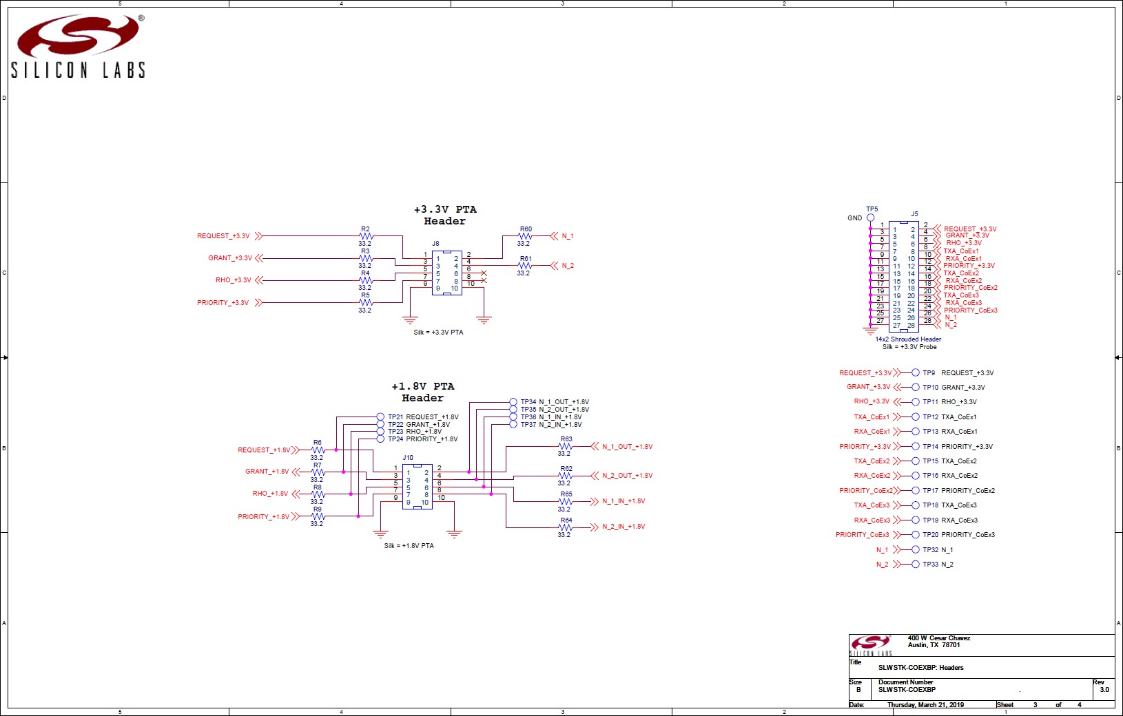
For +3.3 V I/O to Wi-Fi/PTA device, PTA signal connections to Wi-Fi/PTA should be made to J8 as shown in the following table. Add appropriate jumpers and jumper wires based on device configuration explained in Configuring for Different PTA Scenarios.
The +3.3V /IO connections to Wi-Fi/PTA device can be made via +3.3V PTA HDR (J8) as follows:
EFR32 PTA Signal | J8 Pin |
|---|---|
REQUEST_+3.3V | 1 |
GRANT_+3.3V | 3 |
RHO_+3.3V | 5 |
PRIORITY_+3.3V | 7 |
GND | 9 and 10 |
Note: Additional jumpers are required to configure the REQUEST and PRIORITY signals. Jumper configuration varies with single-EFR32 radio and multi-EFR32 radio configurations and active-high/active-low polarities. See Configuring for Different PTA Scenarios for these jumper options.
I/O for +1.8V#
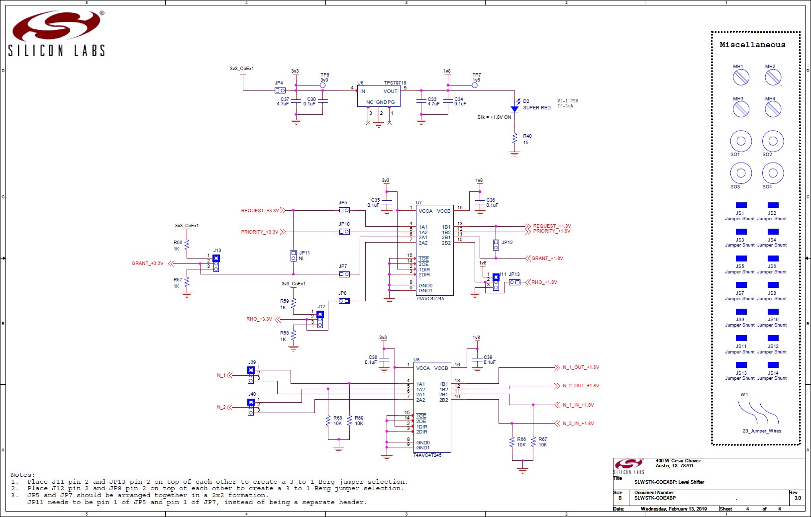
For +1.8V I/O to Wi-Fi/PTA device, assuming typical 3-Wire PTA with RHO unused, PTA signal connections to Wi-Fi/PTA should be made to J10 and all red jumpers shown below are required. Add additional jumpers and jumper wires based on device configuration explained in Configuring for Different PTA Scenarios.
The +1.8 V /IO connections to Wi-Fi/PTA device can be made via +1.8 V PTA HDR (J10) as follows:
EFR32 PTA Signal | J10 Pin |
|---|---|
REQUEST_+1.8V | 1 |
GRANT_+1.8V | 3 |
RHO_+1.8V; (If RHO is used, move J11/JP13 jumper and add J8/J12 jumper) | 5 |
PRIORITY_+1.8V | 7 |
GND | 9 and 10 |
Note: Additional jumpers are required to configure the REQUEST and PRIORITY signals. Jumper configuration varies with single-EFR32 radio and multi-EFR32 radio configurations and active-high/active-low polarities. See Configuring for Different PTA Scenarios for these jumper options.
Probe Header#
The EFR32 PTA signals (+3.3V I/O) are observable via a logic analyzer connected to J5 as shown below:
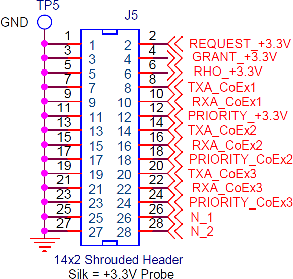
Where:
CoEx1 refers to EFR32/WSTK connected into CoEx1 header (J2)
CoEx2 refers to EFR32/WSTK connected into CoEx2 header (J3)
CoEx3 refers to EFR32/WSTK connected into CoEx3 header (J4)
Note: Depending on jumper configurations, PRIORITY_+3.3 V can be PRIORITY_CoEx1 or wired-OR/-AND of multiple PRIORITY signals. See Configuring for Different PTA Scenarios for these PRIORITY_+3.3 V jumper options.
Board Schematics#
SLWSTK-COEXBP Schematic (1/3)#
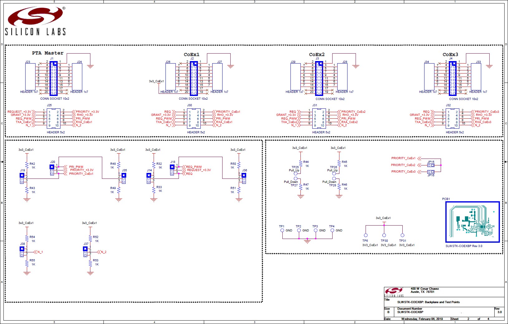
SLWSTK-COEXBP Schematic (2/3)#
SLWSTK-COEXBP Schematic (3/3)#
Packet Trace#
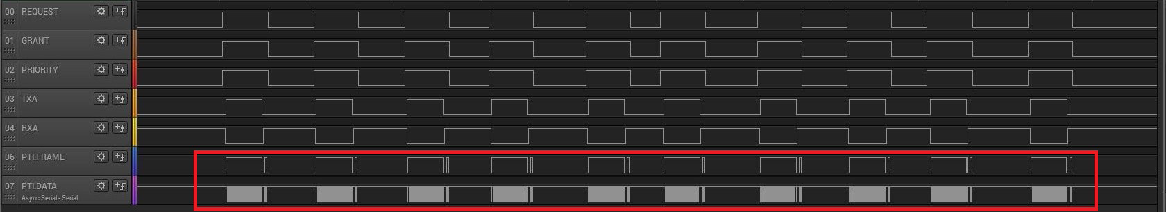
For the purposes of debugging, it can be useful to monitor the packet trace (PTI) signals generated by the radio device. These signals, when viewed with TXA and RXA to indicate radio state, can help determine when a packet was received or transmitted, and whether the radio transaction was successful. To access the PTI signals, some modifications need to be made to the coexistence device’s WSTK board.
Solder a header into the pin locations currently marked as NC. These pins are not connected to any functions on the WSTK board. It is also recommended to add header pins to the adjacent GND pin locations to provide proper ground reference to the logic analyzer.
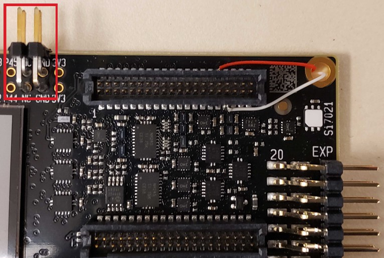
Solder wires to pin 32 and pin 33 of the 40-pin connector. Pin 32 corresponds to the PTI_Frame/PTI_Sync signal, and Pin 33 corresponds to the PTI_DATA signal.
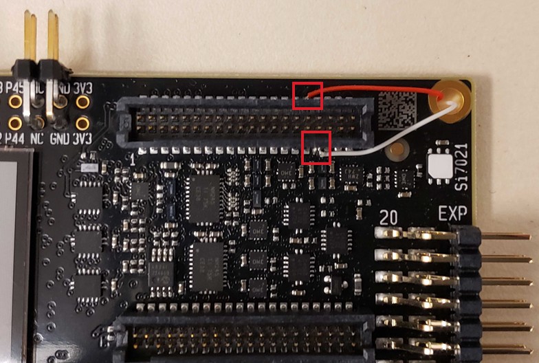
Route these wires to the back of the board and solder onto the header pins that are in the NC pin locations.
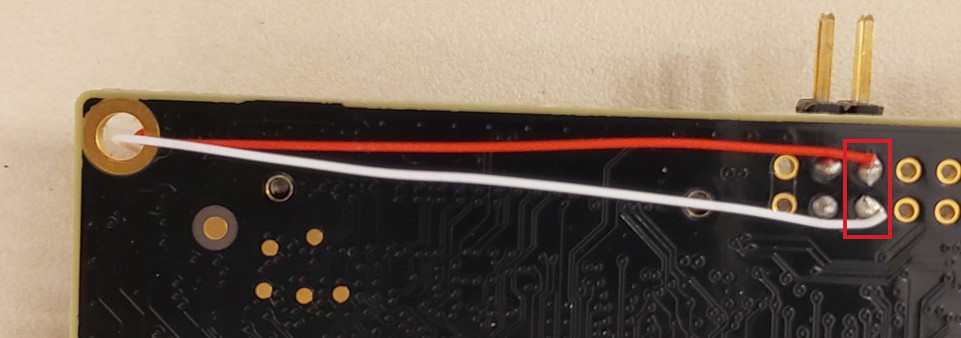
Connect a logic analyzer to the two PTI signals.
The logic analyzer will now be able to capture Packet Trace information alongside coexistence activity from the radio.
For information on how to analyze the PTI data captured, refer to Zigbee and OpenThread Coexistence with Wi-Fi, Bluetooth Coexistence with Wi-Fi, or contact the Silicon Labs support team.