Wi-Fi Impact on Bluetooth and 802.15.4 Radios#
Worldwide, Wi-Fi supports up to 14 overlapping 20/22 MHz bandwidth channels across the 2.4 GHz ISM band with transmit power levels up to +30 dBm. Bluetooth supports 40 non-overlapping channels at 2 MHz spacing with transmit powers up to +20 dBm (Bluetooth Core Specification v5.0). IEEE 802.15.4 supports 16 non-overlapping 2 MHz bandwidth channels at 5 MHz spacing with transmit powers up to +20 dBm. The Bluetooth and 802.15.4 channel mappings are shown in the following figure, where yellow highlighted channels are the three Bluetooth advertising (ADV) channels.
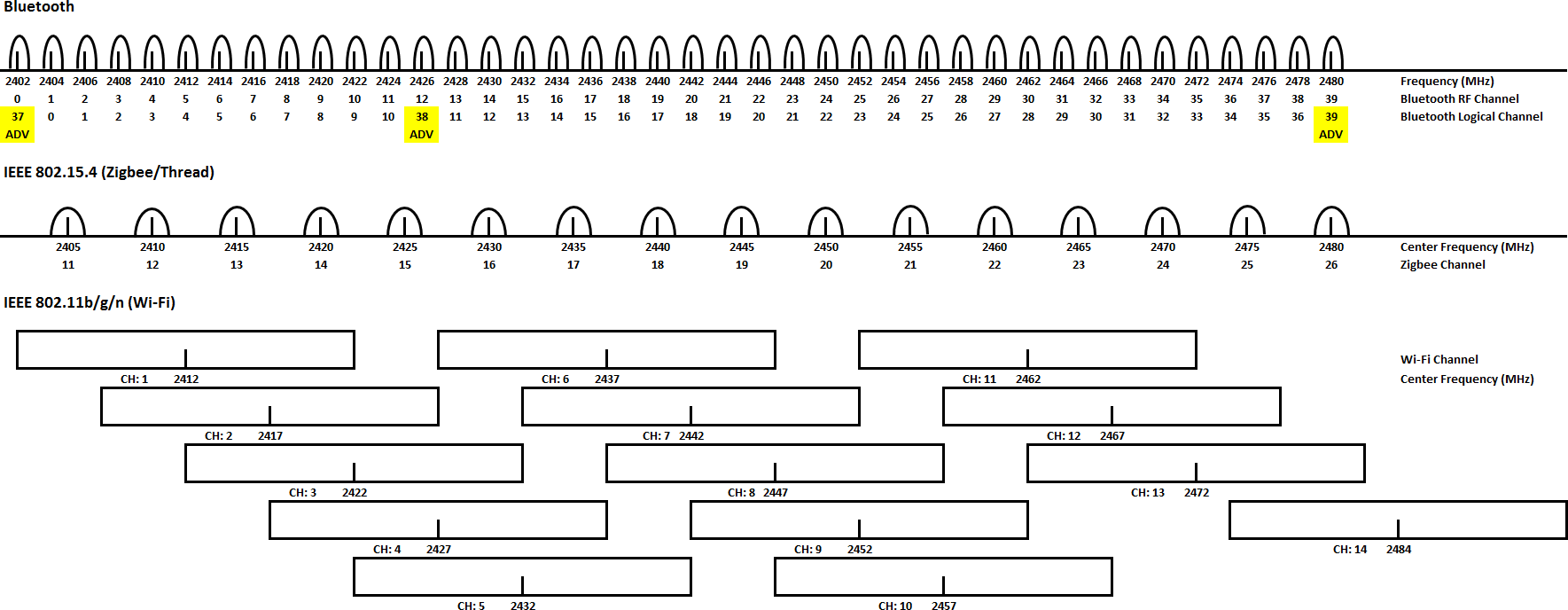
Actual channels available vary by country. For example, in the USA, only Wi-Fi channels 1 through 11 are available. Bluetooth channels 0 through 39 are available worldwide and Zigbee channels 11 through 26 are available, although channels 25 and 26 require reduced transmit power levels to meet FCC requirements (North America only).
Silicon Labs completed testing to understand the effects of Wi-Fi on Bluetooth and 802.15.4 radios. The following subsections summarize the key findings and results from this testing.
Bluetooth#
To better understand the effects of Wi-Fi on Bluetooth, Silicon Labs measured the impact of a 100% duty-cycled 802.11n (MCS3, 20 MHz bandwidth) blocker transmitting at various power levels while receiving a Bluetooth 1Mbps 37-byte payload message transmitted at power level sufficient to achieve 0.1% BER (receive sensitivity). The results for co-channel, adjacent channel, and “far-away” channels are shown in the following figure. All 802.11n and Bluetooth power levels are referenced to the Silicon Labs EFR32MG21 RF input. The test application was developed using the Silicon Labs Bluetooth 2.11.0 or later stack with the soc-dtm sample application running on the EFR32 DUT (Device Under Test) and a test script to control the DUT and RF test equipment.
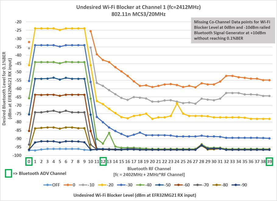
From the figure above, the key observations about the impact of Wi-Fi (channel 1, MCS3/20 MHz) on Bluetooth are:
Co-Channel (Bluetooth overlapping Wi-Fi):
For Bluetooth RF channels 0 through 10, EFR32MG21 can receive a Bluetooth 1Mbps signal at 4 dB weaker than aggregate Wi-Fi transmit power (100% duty cycle).
This receive sensitivity limitation impacts both co-located and remote, not co-located, Bluetooth radios.
Adjacent Channel (Bluetooth within one Wi-Fi bandwidth):
At Bluetooth RF channel 11, EFR32MG21 can receive a -90 dBm Bluetooth 1Mbps with -40 dBm or weaker Wi-Fi transmit power (100% duty cycle).
“Far-Away” Channel (Bluetooth beyond one Wi-Fi bandwidth):
At Bluetooth RF channels 19 through 39, EFR32MG21 can receive a -96 dBm Bluetooth 1Mbps signal with -40 dBm or weaker Wi-Fi transmit power (100% duty cycle).
In a real-world environment, Wi-Fi is typically not 100% duty cycle and only approaches 100% duty cycle during file transfers or video stream in low Wi-Fi SNR conditions. As seen in the previous figure, the EFR32xGxx receive sensitivity varies as the Wi-Fi blocker turns ON/OFF. The net result is the ability to see weaker signals when Wi-Fi is OFF, but not when strong Wi-Fi is ON (actively transmitting).
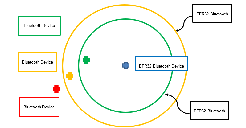
The following figure illustrates the receive range of a node (blue node) near a strong Wi-Fi transmitter. Relative to the blue Bluetooth node, the area inside the green circle represents the receive range when Wi-Fi is ON. The area between the green and yellow circles represents the receive range when Wi-Fi is OFF. From this figure:
The green node is always receivable by the blue node.
The yellow node is only receivable by the blue node when Wi-Fi is OFF.
The red node is never receivable by the blue node.
The yellow and red nodes are always receivable by the green node.
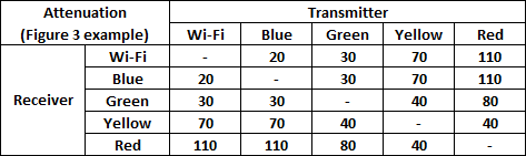
Depending on each Bluetooth device’s TX level, RX sensitivity vs. blocker, channel, and relative attenuation and Wi-Fi TX level and duty cycle, the impact of strong Wi-Fi turning ON/OFF will vary. Based on the figure above, the following example assumes:
Wi-Fi co-located with Blue device
Bluetooth channel is “far-away” (RF channel 39) from Wi-Fi channel (channel 1), indicating minimum Bluetooth RX sensitivity vs. Wi-Fi RX levels:
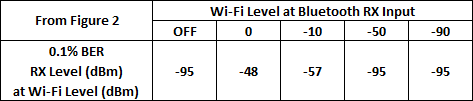
Typical radio TX levels:

Attenuation between radios
Bluetooth device RX success/fail with Wi-Fi OFF:
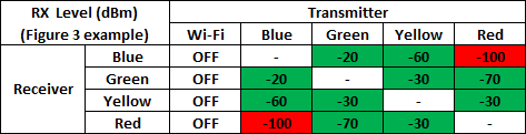
Bluetooth device RX success/fail with Wi-Fi ON:
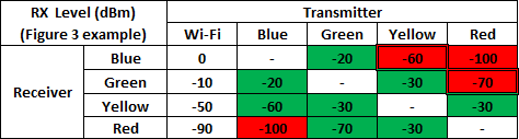
Using the example assumptions, all radio communication is maintained between Wi-Fi ON/OFF except:
Blue device receives yellow device when Wi-Fi ON, but not Wi-Fi OFF.
Green device receives red device when Wi-Fi ON, but not Wi-Fi OFF.
If devices are Bluetooth devices (point-to-point), blue device communication with:
Green device is not impacted by Wi-Fi TX.
Yellow device is erratic as Wi-Fi TX goes ON/OFF.
For high-duty cycle Wi-Fi TX, connection can become unstable as multiple connection intervals fail.
Red device is not possible.
If devices are Bluetooth mesh devices (mesh network), blue device communication with:
Green device is not impacted by Wi-Fi TX.
Yellow device shows erratic communication as Wi-Fi TX goes ON/OFF.
For high-duty cycle Wi-Fi TX, communication would require a relay to forward/repeat missed RX messages from yellow device to blue device.
Red device is not directly possible, and a relay is required to forward messages between blue device and red device.
If green device is relay, communication with red device shows erratic communication as Wi-Fi TX goes ON/OFF.
If yellow device is relay, communication with red device is not impacted by Wi-Fi TX.
802.15.4#
To better understand the effects of Wi-Fi on 802.15.4 radios, Silicon Labs measured the impact of a 100% duty-cycled 802.11n (MCS3, 20 MHz bandwidth) blocker transmitting at various power levels while receiving an 802.15.4 message transmitted at power level sufficient to achieve 1% PER (receive sensitivity). The following figure shows the results for co-channel, adjacent channel, and “far-away” channel. All 802.11n and 802.15.4 power levels are referenced to the Silicon Labs’ EFR32MG21 RF input. The test application was developed using Silicon Labs’ EmberZNet PRO (Zigbee) stack with NodeTest running on the EFR32 DUT (Device Under Test) and a test script to control the DUT and RF test equipment.
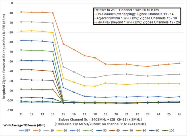
These are the key observations about the impact of Wi-Fi on 802.15.4 from the figure above.
Co-Channel (Zigbee overlapping Wi-Fi):
At channel 12, Zigbee can receive an 802.15.4 signal down to 9 dBm weaker than aggregate Wi-Fi transmit power (100% duty cycle).
This receive sensitivity limitation impacts both co-located and remote, not co-located, 802.15.4 radios.
At channel 12, Zigbee with and without LNA (Low Noise Amplifier) can receive an 802.15.4 signal down to 9 dB weaker than aggregate Wi-Fi transmit power (100% duty cycle).
802.15.4 transmits can also be blocked by Wi-Fi transmit power tripping the 802.15.4 -75 dBm CCA (Clear Channel Assessment) threshold.
Adjacent Channel (Zigbee within one Wi-Fi bandwidth):
At channel 15, Zigbee can receive a -87 dBm 802.15.4 signal with -30 dBm or weaker Wi-Fi transmit power (100% duty cycle).
Maximum receive sensitivity is attained at -38 dBm or weaker Wi-Fi transmit power (100% duty cycle).
At channel 15, Zigbee without LNA can receive a -87 dBm 802.15.4 signal with -30 dBm or weaker Wi-Fi transmit power (100% duty cycle); -34 dBm or weaker with LNA enabled.
“Far-Away” Channel (Zigbee beyond one Wi-Fi bandwidth):
At channels 17 through 26, Zigbee can receive a -96 dBm 802.15.4 signal with -30 dBm or weaker Wi-Fi transmit power (100% duty cycle).
Maximum receive sensitivity is attained at -40 dBm or weaker Wi-Fi transmit power (100% duty cycle).
At channels 17 through 26, Zigbee without LNA can receive a -96 dBm 802.15.4 signal with -30 dBm or weaker 100% Wi-Fi transmit power (100% duty cycle); -34 dBm or weaker with LNA enabled.
In a real-world environment, Wi-Fi is typically not 100% duty cycle and only approaches 100% duty cycle during file transfers or video stream in low Wi-Fi SNR (Signal to Noise Ratio) conditions. As seen in the figure above, the EFR32xGxx receive sensitivity varies as the Wi-Fi blocker turns ON/OFF. The net result is the ability to see weaker signals when Wi-Fi is OFF, but not when strong Wi-Fi is ON (actively transmitting).
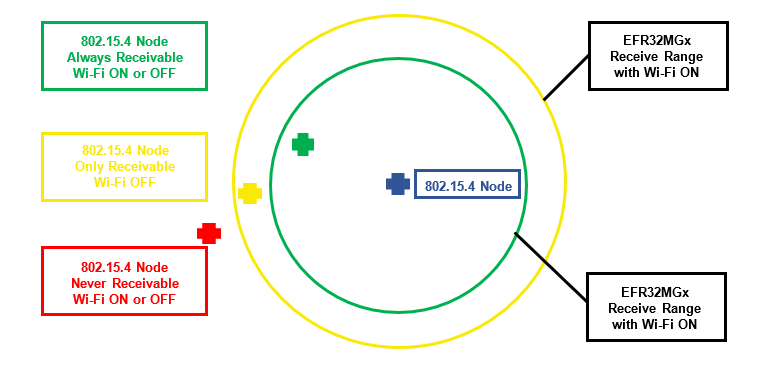
The following figure illustrates the receive range of a node (blue node) near a strong Wi-Fi transmitter. Relative to the blue 802.15.4 node, the area inside the green circle represents the receive range when Wi-Fi is ON. The area between the green and yellow circles represents the receive range when Wi-Fi is OFF. From this figure:
The green node is always receivable by the blue node.
The yellow node is only receivable by the blue node when Wi-Fi is OFF.
The red node is never receivable by the blue node.
The yellow and red nodes are always receivable by the green node.
Depending on each node’s type (Coordinator, Router, or End Device) and the Wi-Fi duty cycle, the impact of strong Wi-Fi turning ON/OFF will vary.
In a Zigbee network:
Coordinator: Tasked with network creation, the control of network parameters, and basic maintenance, in addition to performing an application function, such as aggregating data or serving as a central control point or gateway.
Router: In addition to running an application function, a Router can receive and retransmit data from other nodes.
End Device: Typically, a battery-powered device (Sleepy End Device or SED) running an application function and able to talk to a single parent node (either the Coordinator or a Router). End Devices cannot relay data from other nodes.
In an OpenThread network:
Border Router: Provides network node connectivity to other devices in external networks (for example, Internet access).
Router: In addition to running an application function, a Router can receive and retransmit data from other nodes and provide join and security capability. When routing function is not needed by network, a Router can downgrade to a Router-Eligible End Device (REED).
REED: In addition to running an application function, a REED can receive and retransmit data from other nodes. When additional routers needed by network, a REED can upgrade to a Router.
SED: Typically, a battery-powered device running an application function and able to talk to a single parent node (either a Border Router, Router, or REED). SEDs cannot relay data from other nodes.
Two Zigbee cases are considered below, but many other cases are possible.
Case 1: Zigbee Coordinator near strong Wi-Fi plus three end-nodes#
For this case, the figure above is composed of:
Coordinator: Blue node
End Devices: Green, Yellow, and Red nodes
In this simple network, each end device attempts to join the network formed by the coordinator. However, the red node is outside of receive range and cannot join. With Wi-Fi OFF, both the green and yellow nodes successfully join the network and have no issues sending messages to the Coordinator. Regardless of Wi-Fi ON/OFF duty cycle, the green node remains successful sending messages to the Coordinator.
With Wi-Fi ON/OFF at low-duty cycle, some messages from the yellow node are periodically blocked, but Zigbee retry mechanisms are effective in getting the messages to the coordinator. However, with Wi-Fi ON/OFF at high-duty cycle, many messages from the yellow node are blocked and Zigbee retry mechanisms may be exhausted. Even when retry mechanisms are successful, the message latency increases. If the yellow node is a battery-powered Sleepy End Device, it must remain active longer to execute retries, reducing battery life.
Case 2: Zigbee Coordinator near strong Wi-Fi, Router within always receive range, plus two end-nodes#
For this case, the figure above is composed of:
Coordinator: Blue node
Router: Green node
End Devices: Yellow and Red nodes
In this simple network, the green Router forms a route directly to the Coordinator, maintained regardless of Wi-Fi ON/OFF duty cycle. With Wi-Fi OFF, the yellow node forms a route directly to the blue Coordinator at a lower route cost than a route via the green Router. The red node cannot be received by the Coordinator and its messages are also routed through the Router to the Coordinator.
With Wi-Fi OFF, the green Router, the yellow node, and the red node (via the green Router) have no issues sending messages to the Coordinator. Regardless of Wi-Fi ON/OFF duty cycle, the green Router and the red node (via the green Router) remain successful sending messages to the Coordinator. With Wi-Fi ON/OFF at low-duty cycle, some messages from the yellow node are periodically blocked, but Zigbee retry mechanisms are effective in getting the messages to the Coordinator.
With Wi-Fi ON/OFF at high-duty cycle, many messages from the yellow node are blocked and Zigbee retry mechanisms may be exhausted. If Wi-Fi ON/OFF stays at high-duty cycle for enough time, the network responds by restructuring the yellow node to route messages to the Coordinator via the Router. However, this route rediscover takes time and messages may be lost. If Wi-Fi ON/OFF remains high-duty cycle, the yellow node messages will continue to go through the Router, which forwards messages to the Coordinator.
However, when Wi-Fi ON/OFF returns to low-duty cycle, the network will, due to lower route cost, return to the original structure with the yellow node sending messages directly to the Coordinator.
Under conditions with Wi-Fi ON/OFF switching between low and high duty cycles, the network may switch back and forth between these two route states. During these switching events, messages from the yellow end-node to the Coordinator are lost.