Managed Coexistence#
The market trends of higher Wi-Fi transmit power, higher Wi-Fi throughput, and integration of Wi-Fi and Bluetooth radios into the same device has the following impacts:
Advantages:
Host can implement frequency separation between Wi-Fi, Bluetooth, 802.15.4.
Co-located Wi-Fi radio can force Wi-Fi network to operate with 20 MHz bandwidth.
Co-located Wi-Fi, Bluetooth, and 802.15.4 radios can communicate pending and/or in-progress activity on 2.4 GHz ISM transmits and receives.
Disadvantages:
Higher Wi-Fi transmit power requires greater antenna isolation.
Higher Wi-Fi throughput results in higher Wi-Fi duty cycle.
Antenna isolation is usually limited by the size of the product (only 15-20 dB isolation is not unusual).
Assuming frequency separation achieves the “far-away” channel case and Wi-Fi only uses 20 MHz bandwidth, a +20 dBm Wi-Fi transmit power level at 100% duty cycle requires 50 dB antenna isolation to receive -92 dBm Bluetooth or 45 dB antenna isolation to receive -80 dBm 802.15.4 messages. This is generally not achievable in small devices with co-located Wi-Fi and Bluetooth or 802.15.4.
Managed Coexistence takes advantage of communication between the co-located Wi-Fi, Bluetooth, and 802.15.4 radios to coordinate each radio’s access to the 2.4 GHz ISM band for transmit and receive. For the EFR32, Silicon Labs has implemented a coordination scheme compatible with Wi-Fi devices supporting PTA. This PTA-based coordination allows the EFR32 to signal the Wi-Fi device when receiving a message or wanting to transmit a message. When the Wi-Fi device is made aware of the EFR32 requiring the 2.4 GHz ISM band, any Wi-Fi transmit can be delayed, improving Bluetooth or 802.15.4 message reliability.
Note: EFR32 Bluetooth and Bluetooth Mesh coexistence is supported in Bluetooth 2.13.x and Bluetooth Mesh 2.10.x. Not all coexistence support features in Bluetooth 2.13.x and Bluetooth Mesh 2.10.x are present in earlier versions.
PTA Support Options#
PTA is described in IEEE 802.15.2 (2003) Clause 6 and is a recommendation, not a standard. 802.15.2 originally addressed coexistence between 802.11b (Wi-Fi) and 802.15.1 (Bluetooth Classic) and does not describe an exact hardware configuration. However, 802.15.2 recommends that the PTA implementation consider the following:
TX REQUEST from 802.11b to PTA and TX REQUEST from 802.15.1 to PTA
TX CONFIRM from PTA to 802.11b and TX CONFIRM from PTA to 802.15.1
STATUS information from both radios:
Radio state [TX, RX, or idle]
Current and future TX/RX frequencies
Future expectation of a TX/RX start and duration
Packet type
Priority (Fixed, Randomized, or QoS based)
The following figure describes how 802.15.2 considers radio state, transmit/receive, and frequencies.
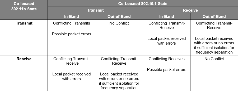
From the figure above, the frequency separation recommendations from section Unmanaged Coexistence remain required for managed coexistence:
802.15.2 “In-Band” is equivalent to Co-Channel operation, which showed significant Wi-Fi impact on co-channel Bluetooth or 802.15.4.
802.15.2 “Out-of-Band” covers both Adjacent and “Far-Away” Channel operation, which showed ~20 dB improvement in “Far-Away” Channel vs. Adjacent Channel (802.15.4).
As such, for Managed Coexistence, Silicon Labs recommends continuing to apply the unmanaged coexistence recommendations described in the following sections:
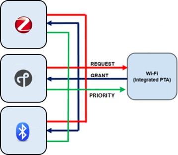
In reviewing existing PTA implementations, Silicon Labs finds the PTA master implementation has been integrated into many Wi-Fi devices, but not all Wi-Fi devices support a PTA interface. Although describing typical PTA implementations is sometimes referred to in the industry as Wi-fi/Bluetooth, 802.15.4 can be used interchangeably with Bluetooth for 1-Wire PTA, 2-Wire PTA, 3-Wire PTA, or 4-Wire PTA when applied to EFR32. The following figure shows the most common Wi-Fi/PTA implementations supporting Bluetooth.
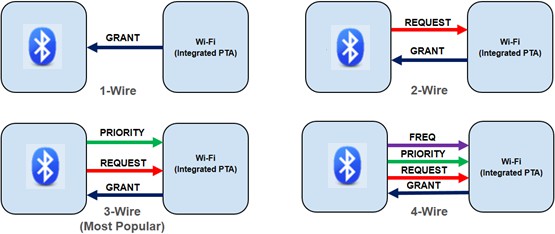
1-Wire PTA#
In 1-Wire PTA, the Wi-Fi/PTA device asserts a GRANT signal when Wi-Fi is not busy transmitting or receiving. When GRANT is asserted, the Bluetooth radio is allowed to transmit or receive. This mode does not allow the external radio to request the 2.4 GHz ISM and is not recommended.
An alternate 1-Wire implementation is a REQUEST signal from Bluetooth to Wi-Fi/PTA, where Bluetooth asserts REQUEST whenever it needs the 2.4 GHz ISM band and expects Wi-Fi to always yield. This mode works very well for Bluetooth, but high priority Wi-Fi traffic can be compromised which impacts Wi-Fi performance.
2-Wire PTA#
In 2-Wire, the REQUEST is added with the GRANT signal, allowing the Bluetooth radio to request the 2.4 GHz ISM band. The Wi-Fi/PTA device internally controls the prioritization between Bluetooth and Wi-Fi, and on a conflict, the PTA can choose to either GRANT Bluetooth or Wi-Fi.
3-Wire PTA#
In 3-Wire, the PRIORITY signal is added, allowing the Bluetooth radio to signify a high- or low-priority message is either being received or transmitted. The Wi-Fi/PTA device compares this external priority request against the internal Wi-Fi priority, which may be high/low or high/mid/low and can choose to either GRANT Bluetooth or Wi-Fi.
PRIORITY can be implemented as static or directional (enhanced) priority.
Static: PRIORITY is either high or low during REQUEST asserted for the transmit or receive operation.
Directional: PRIORITY is either high or low for a typically 20µs duration after REQUEST asserted, but switches to low during receive operation and high during transmit operation.
For platforms, such as Wi-Fi data routers that can achieve high Wi-Fi duty cycles, as well as IoT hubs that stream Bluetooth classic audio, implementing PRIORITY is highly recommended as it provides the Wi-Fi/PTA device with insight on the EFR32 REQUEST. PRIORITY is also configurable, both at compile time and at runtime, to address various product optimization requirements. However, PRIORITY may not be necessary for platforms that do not experience high Wi-Fi duty cycles nor support Bluetooth audio streaming, freeing a GPIO pin on the EFR32 and SoC. Low RF duty cycle protocols such as 802.15.4 are even more likely to not require PRIORITY in these conditions.
4-Wire PTA#
In 4-Wire PTA, the FREQ signal is added, allowing the Bluetooth radio to signify an “in-band” or “out-of-band” message is either being received or transmitted. Silicon Labs recommends maximizing frequency separation, making the FREQ signal mute. For this reason, Silicon Labs’ EFR32 does not support the FREQ signal and, for any 4-wire Wi-Fi/PTA with a FREQ input, Silicon Labs therefore recommends asserting the FREQ input to the Wi-Fi/PTA.
Additional details about the implementation of managed coexistence and test results are available in an expanded version of this application note, AN1243: Timing and Test Data for EFR32 Coexistence with Wi-Fi, available under non-disclosure from Silicon Labs Sales.
Multiple EFR32s Connected to Wi-Fi/PTA#
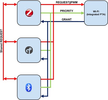
The 802.15.2 recommendation only addresses a single 802.11b radio connected to a single 802.15.1 radio. However, market trends are requiring multiple co-located 2.4 GHz ISM radios to operate with a Wi-Fi/PTA device only designed for one external radio. Silicon Labs has addressed this requirement by enhancing the REQUEST signal with the “shared” REQUEST feature. For 802.15.4 radios only, the Silicon Labs EFR32 PRIORITY can also be configured as “shared” to support additional multi-EFR32 radio configurations.
The “shared” REQUEST and “shared” PRIORITY features have the following characteristics:
Operate REQUEST and PRIORITY in open-drain or open-source (an external 1 kΩ ±5% pull-up for open-drain or pull-down for open source is required).
Before asserting REQUEST, test REQUEST to determine if another EFR32 has already asserted REQUEST.
If not already asserted, assert REQUEST.
If already asserted:
Wait for REQUEST to de-assert.
Delay random time (programmable).
Re-test REQUEST.
If not already asserted, assert REQUEST.
If already asserted:
Then another radio has secured REQUEST.
Return to wait for REQUEST to de-assert.
With these enhanced REQUEST and PRIORITY features, multiple EFR32s implement a PTA interface, which to the Wi-Fi/PTA device appears to be a single external radio.
An example of three EFR32 radios using 2-Wire PTA interfaced to one Wi-Fi/PTA interface using 2-Wire PTA is shown in the following figure (REQUEST pull-up or pull-down not shown).
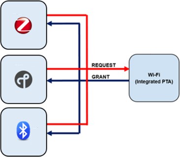
With these enhanced REQUEST features and “shared” PRIORITY, an example of three EFR32 radios using 3-Wire PTA interfaced to one Wi-Fi/PTA interface using 3-Wire PTA is shown in the following figure (REQUEST and PRIORITY pull-ups or pull-downs not shown).
Wi-Fi/PTA Considerations#
From Silicon Labs’ testing, Wi-Fi/PTA implementations vary. Best results are attained when the Wi-Fi/PTA implementation has the following characteristics.
Wi-Fi/PTA Supports Wi-Fi TX Preemption#
Wi-Fi RF duty cycle varies based on the Modulation and Coding Scheme (MCS) index, guard interval, bandwidth, and target data rate. Wi-Fi signal strength and SNR vary with distance and objects/walls between AP and STA, particularly with mobile Wi-Fi devices. When Wi-Fi signal strength and SNR drop, the MCS index is lowered to modulations able to operate at the lower SNR. However, lowering the MSC index also lowers the maximum data rate, and the Wi-Fi RF duty cycle increases as the AP and STA attempt to maintain the target data rate.
After REQUEST asserted, Wi-Fi/PTA devices not supporting Wi-Fi TX preemption delay GRANT to EFR32 until the end of the in-progress packet. At MCS0 with 20MHz bandwidth and large aggregated Wi-Fi packets, this delay can be as long as 16ms. This delay is much longer than the typical REQUEST_WINDOW (Bluetooth) or ~200µs REQUEST to end of CCA, and much longer than the maximum received 802.15.4 packet. (802.15.4). As such, the lack of Wi-Fi TX preemption during high Wi-Fi RF duty cycle increases retries, increases end-node battery consumption, and increases message loss.
After REQUEST asserted, Wi-Fi/PTA devices supporting TX preemption stop the Wi-Fi transmit, ramp down the Wi-Fi PA (within-gate delays up to tens of µs), and quickly GRANT the 2.4GHz band to the radio. The short the time from REQUEST to quiet Wi-Fi and GRANT improves message success on first attempt, which decreases retries, decreases end-node battery consumption, and decreases message loss.
Wi-Fi TX preemption impacts Wi-Fi performance as in-progress Wi-Fi TX packets are aborted and corrupted. In response to a corrupted packet, most Wi-Fi devices assume SNR or interferer and temporarily lower the MCS index to maintain connection but recover to optimum MSC index as subsequent messages are successful. However, Bluetooth and 802.15.4 networks are low duty cycle and the infrequent Wi-Fi TX preemption events have a low impact on Wi-Fi performance.
Wi-Fi/PTA Prevents Wi-Fi Transmit when GRANT Asserted#
Some Wi-Fi/PTA devices have been optimized to work with classic Bluetooth devices and have also been optimized to continue Wi-Fi TX events for a short time after asserting GRANT. This works only for that particular Wi-Fi/PTA and classic Bluetooth combination, as the minimum time from REQUEST asserted to Bluetooth TX start was used to determine how long Wi-Fi TX can continue after GRANT asserted. For EFR32 Bluetooth receives, the Wi-Fi/PTA device must stop all Wi-Fi TX when GRANT asserted and/or the EFR32 REQUEST_WINDOW must be increased to equal or exceed the Wi-Fi/PTA continued TX event.
Some Wi-Fi/PTA devices also attempt Wi-Fi TX based on the FREQ feature described in the 4-Wire PTA. If the FREQ feature is set by GPIO pin (or Wi-Fi/PTA internal register) to different frequencies, Wi-Fi/PTA will assert GRANT, but continue to Wi-Fi transmit. Given co-located Wi-Fi and Bluetooth radios with insufficient antenna isolation, the FREQ feature must be set to always blocking, FREQ GPIO pin (or Wi-Fi/PTA internal register) held asserted.
Wi-Fi/PTA and Application Implements Reasonable Prioritization#
Wi-Fi TX preemption impacts Wi-Fi performance as in-progress Wi-Fi TX packets are aborted and corrupted. In response to a corrupted packet, most Wi-Fi devices assume SNR or interferer and temporarily lower the MCS index to maintain connection but recover to optimum MSC index as subsequent messages are successful. However, Bluetooth and 802.15.4 networks are low duty cycle and the infrequent Wi-Fi TX preemption events have a low impact on Wi-Fi performance.
Bluetooth#
The Bluetooth connection interval and window are fixed. If co-located Bluetooth misses too many connection intervals, the connection is dropped and must be re-established. Frequent drops are unacceptable to end-users. Silicon Labs has implemented priority levels and priority escalation within EFR32. When EFR32 Bluetooth asserts high PRIORITY, the Wi-Fi/PTA devices should GRANT to EFR32, except for only highest priority Wi-Fi traffic.
802.15.4#
802.15.4 RX packets are asynchronous and missing a packet ensures retries, increased message latency, and decreased end-node battery life. As such, 802.15.4 RX priority should be set as high as possible for the application.
802.15.4 TX packets, originating from the co-located Wi-Fi/802.15.4 may have more discretion, as these devices are typically wall powered. However, 802.15.4 transmits showing high latency can result in an unsatisfactory user experience. As such, 802.15.4 TX should also be set as high as possible for the application.
Wi-Fi/PTA Implements Aggregation#
Ensure aggregation is enabled on the Wi-Fi/PTA device. During suitable conditions, aggregation combines multiple smaller packets into fewer larger packets, reducing total packet overhead. As such, aggregation aids Wi-Fi, Bluetooth, and 802.15.4 performance as Wi-Fi TX idle periods combine into larger idle periods for freer RF airtime and improved 802.15.4 PREAMBLE/SYNCH and Bluetooth mesh reception.
Wi-Fi/PTA Supports Directional PRIORITY#
Directional PRIORITY is a common feature that can be enabled on Wi-Fi/PTA devices and is recommended due to the additional radio state information provided by the Bluetooth radio which allows the possibility for concurrent Wi-Fi and Bluetooth reception when utilizing channel separation as well as concurrent Wi-Fi and Bluetooth transmission, also when utilizing channel separation. In this way, implementing Pulsed Directional PRIORITY maximizes Wi-Fi and Bluetooth throughput.
TX PRIORITY Escalation (802.15.4)#
To improve Wi-Fi performance with 802.15.4 coexistence, it is possible to start all 802.15.4 TX messages at low priority. However, to avoid blocking, all 802.15.4 TX messages during busy Wi-Fi, TX PRIORITY Escalation will escalate TX to high priority after a programmable number of CCA/GRANT or MAC failures. Then, after a successful TX message, de-escalate TX back to low priority.
Signal Identifier for High Duty Cycle Wi-Fi#
Background#
The following figure shows a 15.485 ms capture of the Wi-Fi TX Active signal during maximum-throughput iperf TCP transmission. The waveform contains multiple Wi-Fi TX idle periods. The first group of idle periods is shown in an expanded view.
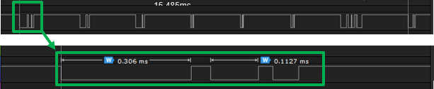
From the first group, only the 0.306ms idle period is sufficient for packet receive (Bluetooth) or PREAMBLE/SYNCH detection (802.15.4) with a 0.146ms detection window (0.306ms–0.160ms). The following table lists all Wi-Fi TX idle period durations in the above 15.485ms capture.
Wi-Fi TX Idle (ms) | Detection Window (Idle–0.160ms) |
|---|---|
0.306 | 0.146 |
0.113 | 0.000 |
0.061 | 0.000 |
0.246 | 0.086 |
0.077 | 0.000 |
0.260 | 0.100 |
0.061 | 0.000 |
0.065 | 0.000 |
0.016 | 0.000 |
0.065 | 0.000 |
0.016 | 0.000 |
0.065 | 0.000 |
0.016 | 0.000 |
0.245 | 0.085 |
0.105 | 0.000 |
0.098 | 0.000 |
0.016 | 0.000 |
0.171 | 0.011 |
The sum of all Wi-Fi TX Idle periods is 2.002ms. This Wi-Fi TX Activity indicates 87.1% duty cycle [(15.485–2.002) / 15.485 x 100%], but this calculation does not include the additional Wi-Fi RX activity.
The sum of all Detection Windows is 0.428ms, providing only 2.8% probability of receiving the packet [0.428 / 15.485 x 100%]. But again, this calculation does not include Wi-Fi RX Activity. With only 2.8% probability of packet reception and a target 1% or less BT Mesh message loss, 165 retries are required [CEILING(LOG(1%)/LOG(100%–2.8%)]. This large number of required retries is far beyond the Bluetooth mesh network retries and, even if retries are extended, the message latency becomes impractical. Large retries also quickly degrade lifetime for battery power end-nodes.
To resolve this issue, Bluetooth or 802.15.4 radios require additional RF airtime to listen for incoming packets without being blocked by co-located Wi-Fi transmissions. The following options are available:
Limit the Wi-Fi TX RF duty cycle
Configure the co-located Wi-Fi device to enforce a maximum allowed Wi-Fi TX RF duty cycle.
Use the Signal Identifier feature
Configure the co-located Bluetooth or 802.15.4 radio to use the unique Signal Identifier feature, which improves detection probability even in high-duty-cycle Wi-Fi environments.
Assert REQUEST at high PRIORITY
Configure the co-located Bluetooth or 802.15.4 radio to assert
REQUESTat highPRIORITY, forcing the Wi-Fi transmitter to enter regular quiet periods.
Silicon Labs has not found option #1 to be reliable over various Wi-Fi/PTA devices. Option #2 is covered in this section of this document. Silicon Labs has developed a PWM extension feature to support option #3 (For more details, see PWM for High Duty Cycle Wi-Fi.)
Signal Identifier Feature Description#
The Signal Identifier feature in supported devices, such as the EFR32xG24, uses a signal detector to detect IoT signals (802.15.4 or Bluetooth) during Wi-Fi's required inter-frame spacing (IFS) and interrupts the Wi-Fi radio only when a signal is detected. Upon signal detection, PTA REQUEST is asserted to halt Wi-Fi TX and capture the expected retry signal. This feature can be used to improve RX performance in high-duty-cycle Wi-Fi scenarios with minimal impact on maximum Wi-Fi throughput.
Two options are available for using the Signal Identifier feature. The difference between these variants is the method used to reset the internal signal detector that identifies a valid 802.15.4 or Bluetooth signal.
GPIO-based SI:#
For this option, configure an additional GPIO input and drive it with the Wi-Fi TX Active signal (typically the Wi-Fi TX FEM PAEN signal) to restart signal detection when Wi-Fi TX is deasserted. This approach generally provides the fastest detection of the two options. If the device schematic and layout allow for this additional connection, Silicon Labs recommends implementing this option.
AGC-based SI:#
With this option, signals from the radio's internal Automatic Gain Control (AGC) block are used to detect inactive periods during Wi-Fi TX. Because no additional GPIO connection is required between the EFR32 device and the Wi-Fi device, this option is well suited for designs with hardware constraints.
802.15.4#
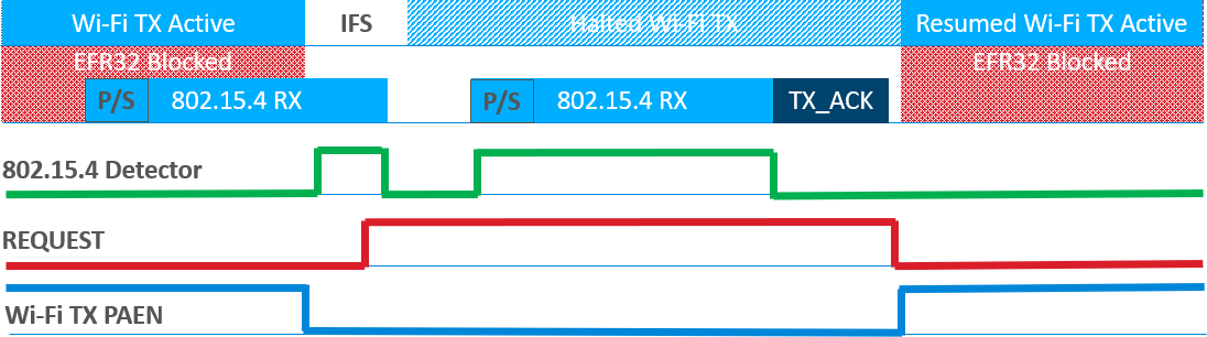
The standard 802.15.4 packet detection requires the PREAMBLE/SYNC sequence (160 µs) to align with Wi-Fi TX idle periods, resulting in a low detection probability at high Wi-Fi duty cycles. The Signal Identifier feature enables the device to detect a valid 802.15.4 signal much more quickly and does not require PREAMBLE/SYNC alignment for signal detection. Note that PREAMBLE/SYNC alignment is still required for successful 802.15.4 packet reception. As a result, at least one retry may still occur during high-duty-cycle Wi-Fi operation. However, this method significantly increases the probability of signal detection, reduces end-node retries and latency, and improves end-node battery life.
The following figure illustrates the improved signal detection process. When the 802.15.4 signal detector detects a signal during the Wi-Fi IFS, PTA REQUEST is asserted to halt Wi-Fi TX and allow the retransmitted packet to be received. REQUEST is deasserted after the device successfully receives the packet and confirms reception with an ACK. If an 802.15.4 packet is not received before the programmable Receive Retry timeout expires, REQUEST is deasserted, allowing Wi-Fi operation to resume.
For more information on configuring the 802.15.4 signal identifier, see Zigbee and OpenThread Coexistence with Wi-Fi.
Bluetooth#
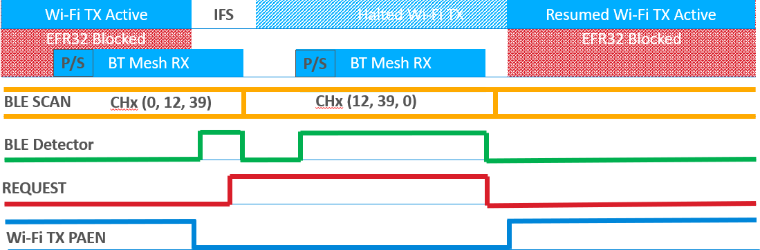
If the signal identifier module triggers when the Bluetooth radio is scanning and Bluetooth PREAMBLE/SYNCH is not detected, then the radio quickly switches to next primary advertising channel in an effort to capture the ADV event repeated over all three primary advertising channels.
This feature is most useful on BT Mesh using ADV bearer method as all messages are sent over ADV channels at an unknown arrival timing.
If a Bluetooth packet is received after switching ADV channels, the packet is processed, which may include multiple RX/TX events. When the ADV event is finished, the REQUEST signal is de-asserted, allowing Wi-Fi operation to resume. The time-out after switching is programmable and, if no packet is received within time-out, the REQUEST signal is de-asserted, allowing Wi-Fi operation to resume.
For more information on configuring the Bluetooth signal identifier, see Bluetooth Coexistence with Wi-Fi.
PWM for High Duty Cycle Wi-Fi#
PWM is a feature that allows the EFR32 to reserve a timed slot for REQUEST assertion. This can be beneficial in high-duty-cycle Wi-Fi environments because scheduled EFR32 TX and RX activity enables the Wi-Fi device to more readily grant airtime when it is anticipated. Note that GRANT is not guaranteed; the Wi-Fi device ultimately determines whether to provide airtime.
This PWM feature can be applied to any use case in which EFR32 Bluetooth Passive Scan, Bluetooth Mesh, or 802.15.4 packet reception is impaired by a co-located, controllable external device. This includes, but is not limited to, the following use cases:
High duty-cycle co-located Wi-Fi TX
Bluetooth or 802.15.4 co-channel with Wi-Fi
External T/R switch requiring Bluetooth or 802.15.4 to share a single antenna with Wi-Fi
Bluetooth#
100% Passive SCAN and Bluetooth mesh have no knowledge of when an incoming packet will arrive. As the co-located Wi-Fi TX RF duty cycle increases, the Wi-Fi TX idle periods become smaller and there are fewer idle periods allowing Passive SCAN or Bluetooth mesh receives. As such, the probability of a packet arriving during an acceptably large Wi-Fi TX idle period decreases significantly.
The PWM feature implements regular PTA REQUESTs to interrupt the high Wi-Fi RF duty cycle and ensure adequate windows for receives. However, this feature does degrade Wi-Fi performance. Additionally, the exact PWM period and duty cycle must be carefully selected to not alias PWM period with Wi-Fi beacons to avoid collapsing the Wi-Fi network.
Note: Ensure aggregation is enabled on Wi-Fi/PTA device. During suitable conditions, aggregation combines multiple smaller packets into fewer larger packets which reduces the total packet overhead. As such, aggregation aids Passive SCAN and Bluetooth mesh ADV-Bearer packet detection as Wi-Fi TX idle periods combine into larger idle periods.
802.15.4#
802.15.4 radios have no knowledge of when an incoming packet will arrive and must capture the 802.15.4 PREAMBLE/SYNCH (160µs duration) to detect an incoming packet. As the co-located Wi-Fi TX RF duty cycle increases, the Wi-Fi TX idle periods become smaller and there are fewer idle periods exceeding 160µs. As such, the probability of a 160µs PREAMBLE/SYNCH arriving during an acceptably large Wi-Fi TX idle period decreases significantly.
The PWM feature implements regular PTA REQUESTs to interrupt the high Wi-Fi RF duty cycle and ensure adequate windows for PREAMBLE/SYNCH detection. However, this feature does degrade Wi-Fi performance. Additionally, the exact PWM period and duty cycle must be carefully selected to not alias PWM period with Wi-Fi beacons to avoid collapsing the Wi-Fi network.
Note: Ensure aggregation is enabled on Wi-Fi/PTA device. During suitable conditions, aggregation combines multiple smaller packets into fewer larger packets which reduces the total packet overhead. As such, aggregation aids 802.15.4 packet detection as Wi-Fi TX idle periods combine into larger idle periods for improved PREAMBLE/SYNCH detection.
PWM Feature Description#
The PWM feature does not require any additional GPIOs for single EFR32 designs. However, multi-EFR32 designs require an additional GPIO to be available for each EFR32.
Bluetooth#
The PWM feature is used to periodically stop co-located Wi-Fi TX activity to ensure sufficient idle TX time windows to receive Bluetooth packets during Passive SCAN and Bluetooth mesh ADV-Bearer receive.
The optimum PWM period and duty cycle can vary based on Bluetooth operation and Wi-Fi activity. If Wi-Fi activity is low, PWM could be disabled and fall back to normal PTA activity as described in PWM for High Duty Cycle Wi-Fi. During very high Wi-Fi duty cycle for Bluetooth mesh ADC-Bearer, a PWM programmed to 39ms period and >44% duty is effective in reducing message loss to less than 1%. As noted, Wi-Fi throughput is impacted and, under 39ms/>44% condition, the high duty cycle Wi-Fi TX throughput noted above dropped ~50%.
802.15.4#
Under the same Wi-Fi TX Active throughput conditions as in section Background, the following figure shows the REQUEST||PWM (shown as REQUEST||TIMER1) signal interrupting the Wi-Fi TX with a 19.5 ms period and 20% duty cycle, sufficient to allow 802.15.4 RX with < 1% message loss.
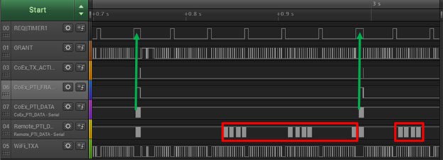
The green arrows show cases where the PREAMBLE/SYNCH was detected during a high PWM cycle, driving REQUEST||PWM high. This high PWM cycle stopped Wi-Fi TX Activity to allow detection of incoming 802.15.4 PRERAMBLE/SYNCH. As also seen, the REQUEST||PWM cycle is longer than all other cycles due to assertion of normal PTA REQUEST signal OR’ed with PWM cycle.
The red boxes are cases where the remote 802.15.4 radio executed packet transmits that were not detectable due to Wi-Fi TX Activity and packets’ PREAMBLE/SYNCH not aligning with the PWM cycle.
Optimum PWM period and duty cycle can vary based on 802.15.4 operation and Wi-Fi activity. If Wi-Fi activity is low, PWM could be disabled and fall back to normal PTA activity as described earlier. During very high Wi-Fi duty cycle for unicast 802.15.4 traffic, a PWM programmed to 19.5 ms period and 20% duty is effective in reducing message loss to less than 1% with APS retries disabled. As noted, Wi-Fi throughput is impacted and, under 19.5 ms/20% condition, the high duty cycle Wi-Fi TX throughput noted above dropped ~20% (~270 Mbps without PWM to ~220 Mbps with PWM).
During very high Wi-Fi duty cycle for broadcast 802.15.4 traffic without ACKs (for example, as occurs during network join sequence), a higher PWM duty cycle is required (e.g., 19.5 ms period and 80% duty cycle). This higher duty cycle can be disruptive to Wi-Fi but is only needed during expected broadcast message activity. This higher duty cycle can be reduced as soon as broadcast activity (for example, device join) completes.
PWM Implementation#
The optimum PWM implementation varies with single-EFR32 vs. multi-EFR32 applications. This implementation difference is primarily due to the REQUEST sharing feature used in multi-EFR32 applications. However, if addressed during circuit board design, this difference is easily resolved.
Bluetooth#
Use of an BGAPI or CLI command are needed to allow the host application to control the PWM period, duty cycle, and priority. For more information, see Bluetooth Low Energy Coexistence with Wi-Fi.
802.15.4#
Use of an API or coexistence CLI command are needed to allow the host application to control the PWM period, duty cycle, and priority. For more information, see Zigbee and OpenThread Coexistence with Wi-Fi.
Multi-EFR32 Radio with PWM#
For multi-EFR32 radio applications not implementing PWM, the Shared REQUEST signal is used to arbitrate which EFR32 radio has access to the 2.4 GHz ISM band when GRANT is asserted from the Wi-Fi/PTA. If the PWM signal were to be applied to the shared REQUEST pin, other EFR32 radios would interpret the REQUEST as busy when it might just be forcing Wi-Fi TX idle to allow any of the IoT radios to detect an incoming packet. Instead, the Shared REQUEST feature is accommodated by separating the Shared REQUEST signal from the REQUEST||PWM signal resulting in a separate non-Wi-Fi/PTA signal connection between the EFR32 devices for Shared REQUEST.
The PWM enabled Wi-Fi/PTA connections between the Wi-Fi and Zigbee, OpenThread, and BLE EFR32 radios are the same as the multi-EFR32 radio with typical 3-Wire PTA schema. Only one radio, selected at run time, controls the PWM and ORs the PWM signal in software with its own REQUEST (arbitrated by the Shared REQUEST signal). The other EFR32 radios must also implement PWM in Hardware Configurator to provide their REQUEST to the PTA interface, (also arbitrated by Shared REQUEST). Each EFR32 radio’s REQUEST||PWM GPIO is set to open-drain/open-source, allowing a hardware OR function of any EFR32 radio’s REQUEST with REQUEST||PWM.
If the radio driving REQUEST||PWM needs to go off-line (for example, for a firmware update), its PWM outputs can be halted and another EFR32 radio’s PWM outputs can then be activated for continued PWM operation. In the following figure (REQUEST and PRIORITY pull-ups and pull-downs not shown), the Zigbee radio implements the PWM feature and the Thread radio or the Bluetooth radio provide PWM backup.
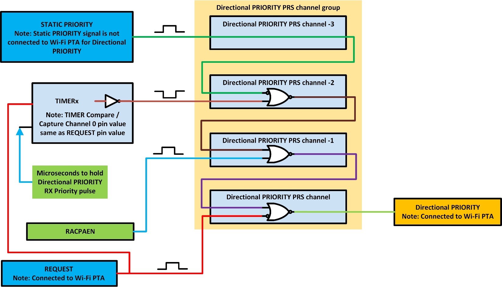
Directional PRIORITY#
Directional PRIORITY provides radio state information on the same signal line as PRIORITY by a timed pulse indicating a priority transaction, followed by a radio state indicating to the Wi-Fi part that the EFR32 is transmitting or receiving. PRIORITY signal options must be configured for implementing Directional PRIORITY.
Directional PRIORITY requires the use of a Timer and either four PRS channels (EFR32xG2x) or five PRS channels (EFR32xG1x). When Directional PRIORITY is enabled, the designer will need to verify the Timer and PRS channels selected for Directional PRIORITY are not used by the protocol SDK stack, plugins or custom application code.
RACPAEN and REQUEST is either one PRS channel which inverts ORs in one operation (EFR32xG2x) or two separate PRS channels (EFR32xG1x).
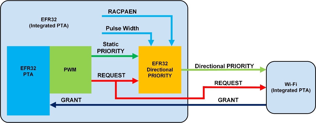
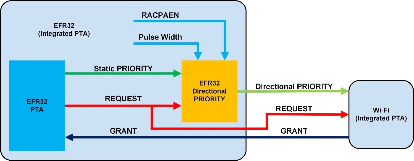
Single-EFR32 PTA with Directional PRIORITY#
The following figures show the GPIO, Radio, and Timer signals for Single-EFR32 PTA with and without SDK PWM and with Directional PRIORITY.
Directional PRIORITY#
EFR32 Directional Priority output.
GPIO connects to Wi-Fi PTA.
Requires active high Static PRIORITY and active high REQUEST
Static PRIORITY#
EFR32 PTA output.
Directional PRIORITY input.
The active high PRIORITY is not assigned to a GPIO.
Not connected to any external circuit.
REQUEST#
EFR32 PTA output.
Directional PRIORITY input.
Compared in Pulse Width Timer.
GPIO connects to Wi-Fi PTA.
GRANT#
EFR32 PTA input.
GPIO connects to Wi-Fi PTA.
RACPAEN#
EFR32 radio transmit PA enable output.
Directional PRIORITY input.
Pulse Width#
EFR32 Timer compared with REQUEST GPIO.
Directional PRIORITY input.
Multi-EFR32 PTA with Directional PRIORITY#
The following figure shows the GPIO, Radio, and Timer signals for Multi-EFR32 PTA with SDK PWM and Directional PRIORITY (1K 5% pull-ups and pull-downs not shown).
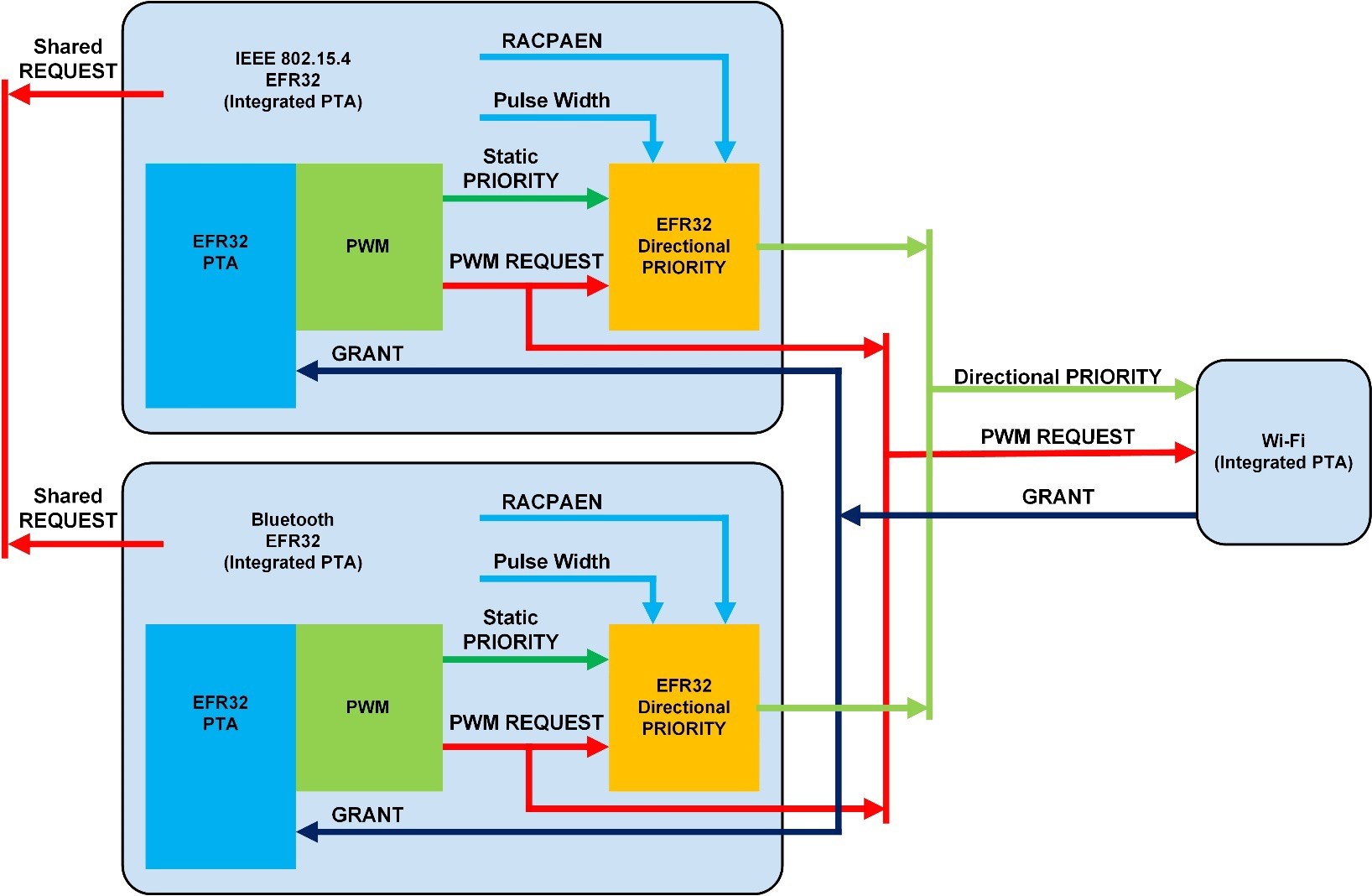
Shared REQUEST
EFR32 PTA input / output.
GPIO connects to all EFR32s for PTA bus arbitration between EFR32s
Configured as open source / drain.
The active high Shared REQUEST is open-source and an external 1 kΩ ±5% pull-down is required.
Directional PRIORITY#
EFR32 Directional Priority output
GPIO Connects to Wi-Fi PTA and all EFR32s
Configured as open source / drain.
The active high Directional PRIORITY is open-source and an external 1 kΩ ±5% pull-down is required.
Static PRIORITY#
EFR32 PTA output.
Directional PRIORITY input.
The active high PRIORITY is not assigned to a GPIO.
Not connected to any external circuit.
PWM REQUEST#
EFR32 PTA output.
Directional PRIORITY input.
GPIO Connects to Wi-Fi PTA and all EFR32s.
Configured as open source / drain.
If active high, PWM REQUEST is open-source and an external 1 kΩ ±5% pull-down is required.
Compared with Pulse Width in EFR32 Timer.
GRANT#
EFR32 PTA input.
GPIO connects to Wi-Fi PTA and all EFR32s.
RACPAEN#
EFR32 Radio transmit PA enable output.
Directional PRIORITY input.
Pulse Width#
EFR32 Timer compared with PWM REQUEST GPIO.
Directional PRIORITY input.
The following figure shows the PRS and Timer logic diagram for Directional PRIORITY for EFR32xG1x.
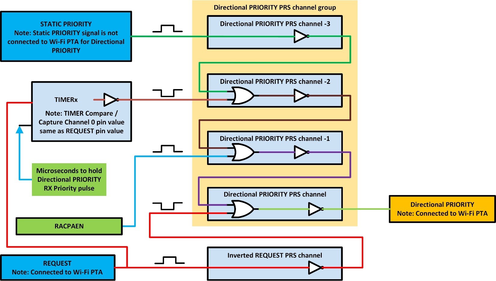
The following figure shows the PRS and Timer logic diagram for Directional PRIORITY for EFR32xG2x.