Configuring Wi-Fi Coexistence#
This section describes how to configure the Silicon Labs Packet Traffic Arbitration (PTA) using the Simplicity Studio Component Editor for Zigbee and OpenThread.
PTA Software Setup with the Component Editor (Zigbee and OpenThread)#
The steps to set up PTA Software for Zigbee and OpenThread using the Component Editor are described below. These steps assume you have installed Simplicity Studio 5, EmberZNet SDK 7.x, and the OpenThread SDK, and that you have a project open in the Simplicity IDE.
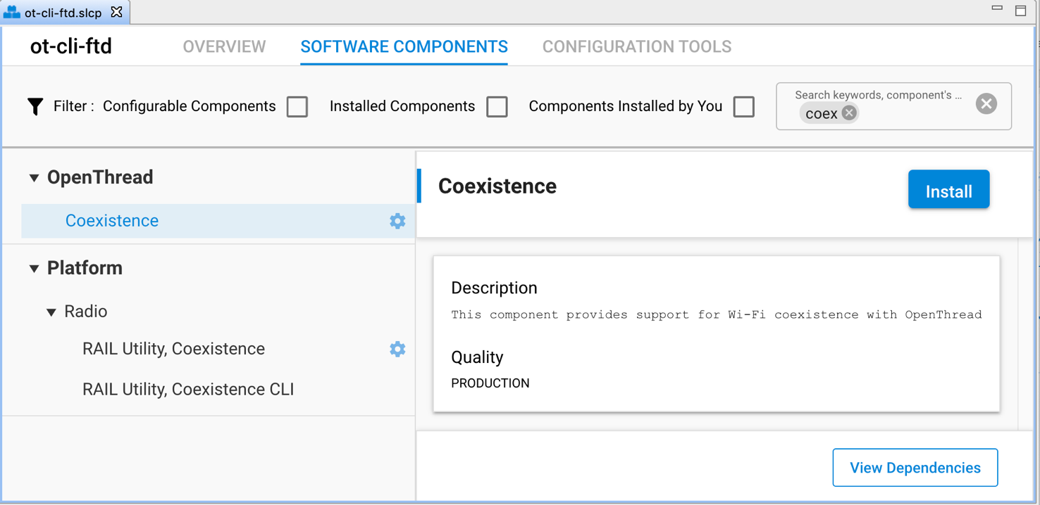
On the SOFTWARE COMPONENTS tab, search for coex in the component’s name search field (at the top right).
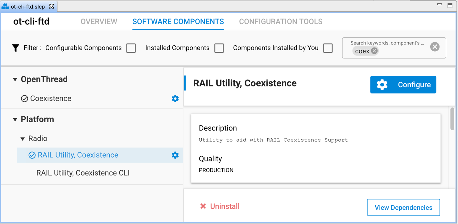
For Zigbee, under Platform->Radio components, select and install the RAIL Utility, Coexistence component directly under Platform components.
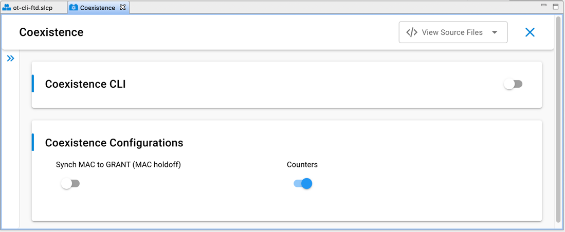
For OpenThread, under OpenThread components, select the Coexistence component and click Install as shown in the following figure. Installing the Coexistence component will install the RAIL Utility, Coexistence component for your project.
Note: For Silicon Labs OpenThread SDK releases prior to 1.2.0.0, select and install the RAIL Utility, Coexistence component directly under Platform components.
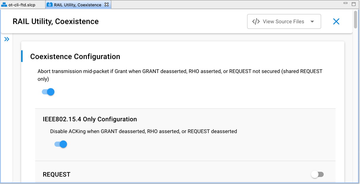
Once the relevant coexistence component(s) are successfully installed, click Configure or the configure symbol next to the RAIL Utility, Coexistence component name to open the coexistence properties as shown in the following figure.
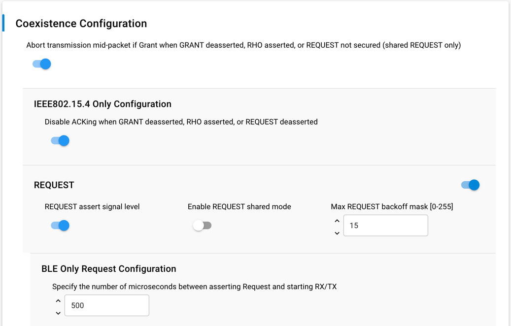
The following figures show the different coexistence properties in the Component Editor. For more information on coexistence properties, see Coexistence Configurations below.
Coexistence Configurations#
The following subsections describe the coexistence configurations in detail.
Note: To configure GPIO pins for a coexistence signal in the Component Editor, use the equivalent SL_RAIL_UTIL_COEX <signal> section of the configuration header.
REQUEST#
REQUEST signal enabled#
If selected, REQUEST is mapped to GPIO pin and is used by PTA implementation.
If not selected, REQUEST is not mapped to GPIO pin.
REQUEST signal is shared
If selected, REQUEST is shared and implements open-drain or open-source I/O for multi-EFR32 radio applications.
If active low, REQUEST is open-drain and an external 1 k ±5% pull-up is required.
If active high, REQUEST is open-source and an external 1 k ±5% pull-down is required.
If not selected, REQUEST is not shared and implements a push-pull output for single EFR32 radio applications.
REQUEST signal active high#
If selected, REQUEST GPIO pin is driven high (> Voh) when REQUEST is asserted.
If not selected, REQUEST GPIO pin is driven low (< Vol) when REQUEST is asserted.
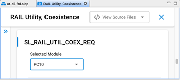
REQUEST signal GPIO port and REQUEST signal GPIO pin#
Select REQUEST port and pin matching circuit board configuration.
To configure GPIO port and pin for the REQUEST signal in the Component Editor, use the SL_RAIL_UTIL_COEX_REQ section of the configuration header.
REQUEST signal max backoff mask [0-255]#
REQUEST signal max backoff determines the random REQUEST delay mask (only valid if REQUEST signal is shared).
Random delay (in µs) is computed by masking the internal random variable against the entered mask.
The mask should be set to a value of 2n-1 to insure a continuous random delay range.
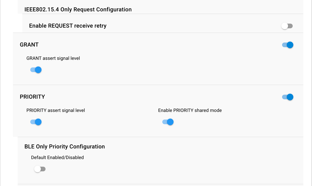
Receive Retry#
Receive retry REQUEST enabled#
If selected, REQUEST is held after a corrupted receive packet or after a successful receive packet with GRANT denied until timeout expires, or another packet is received.
Note: This feature is useful to hold 2.4 GHz band clear while the remote device re-transmits a packet, maximizing the opportunity to receive an uncorrupted retry packet from the remote device, reducing 2.4 GHz RF traffic and improving battery life.
If not selected, REQUEST is not held after a corrupted receive packet or after a successful receive packet with GRANT denied.
Receive retry timeout (milliseconds) [0-255]#
Selects the timeout for REQUEST hold after a corrupted receive packet.
Notes:
16ms is recommended to allow for maximum 802.15.4 packet duration and MAC retry random delay.
Many Wi-Fi/PTA implementations have a maximum GRANT timeout, which should be set to received retry timeout plus 6ms to allow for maximum size corrupted packet, maximum random delay, and maximum size retry packet.
The Receive Retry timeout is used by the 802.15.4 Signal Identifier for supported devices (like the EFR32xG24) as the timeout after asserting REQUEST from signal identifier.
REQUEST high PRIORITY on receive retry#
If selected, PRIORITY is asserted during REQUEST hold after a corrupted receive packet or after a successful receive packet with GRANT denied.
If not selected, PRIORITY is de-asserted during REQUEST hold after a corrupted receive packet or after a successful receive packet with GRANT denied.
GRANT#
GRANT signal enabled#
If selected, GRANT is mapped to GPIO pin and is used by PTA implementation.
If not selected, GRANT is not mapped to GPIO pin and GRANT is always asserted.
GRANT signal active high#
If selected, GRANT is asserted when GRANT GPIO pin is high (> Vih).
If not selected, GRANT is asserted when GRANT GPIO pin is low (< Vil).
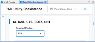
GRANT signal GPIO port and GRANT signal GPIO pin#
Select GRANT port and pin matching circuit board configuration.
To configure GPIO port and pin for the GRANT signal in the Component Editor, use the SL_RAIL_UTIL_COEX_GNT section of the configuration header.
Abort Transmission Mid Packet If GRANT Is Lost#
If selected, losing GRANT during an 802.15.4 TX will abort the 802.15.4 TX.
If not selected, losing GRANT after the initial evaluation at end of CCA will not abort the 802.15.4 TX.
Note: In the Component Editor, this option has been moved from the GRANT section to the common section of the configuration header.
ACK Disable#
Disable ACKing when GRANT de-asserted, RHO asserted, or REQUEST not secured (shared REQUEST only)
If selected, the ACK to a valid RX packet, requiring an ACK, is not transmitted if GRANT is de-asserted, RHO is asserted, or REQUEST is not secured (shared REQUEST only).
Note: This feature allows completing an 802.15.4 message, regardless of PTA signals, to minimize additional retries from remote device, reducing 2.4 GHz RF traffic and improving battery life.
If not selected, the ACK to a valid RX packet requiring an ACK is transmitted regardless of GRANT, RHO, or REQUEST state.
Note: In the Component Editor, this option has been moved from the GRANT section to the common (IEEE802.15.4 Only Configuration) section of the configuration header.
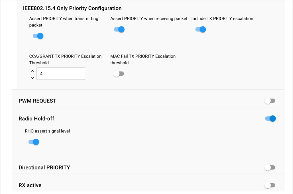
PRIORITY#
PRIORITY signal enabled#
If selected, PRIORITY is mapped to GPIO pin and is used by PTA implementation.
If not selected, PRIORITY is not mapped to GPIO pin.
PRIORITY signal active high#
If selected, PRIORITY GPIO pin is driven high (> Voh) when PRIORITY is asserted.
If not selected, PRIORITY GPIO pin is driven low (< Vol) when PRIORITY is asserted.
If Enable Directional PRIORITY equals True, PRIORITY assert signal level must be set to High.
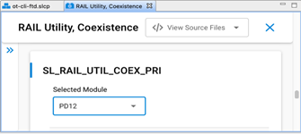
PRIORITY signal GPIO port and PRIORITY signal GPIO pin#
Select PRIORITY port and pin matching circuit board configuration.
To configure GPIO port and pin for the PRIORITY signal in the Component Editor, use the SL_RAIL_UTIL_COEX_PRI section of the configuration header.
Enable PRIORITY shared mode
If enabled. PRIORITY is shared and implements open-drain or open-source I/O for multi-EFR32 radio applications.
If active low, PRIORITY is open-drain and an external 1 k ±5% pull-up is required.
If active high, PRIORITY is open-source and an external 1 k ±5% pull-down is required.
If not enabled, PRIORITY is not shared and implements a push-pull output for single EFR32 radio applications.
TX high PRIORITY#
If selected, PRIORITY is asserted during 802.15.4 TX.
If not selected, PRIORITY is de-asserted during 802.15.4 TX.
RX high PRIORITY#
If selected, PRIORITY is asserted during 802.15.4 RX.
If not selected, PRIORITY is de-asserted during 802.15.4 RX.
Include TX PRIORITY Escalation#
If enabled. TX PRIORITY Escalation feature is compiled into firmware.
If not enabled, TX PRIORITY Escalation feature is not compiled into firmware and CCA/GRANT TX PRIORITY Escalation Threshold and MAC Fail TX PRIORITY Escalation Threshold must be set to 0 when writing to ptaOptions via run-time API.
CCA/GRANT TX PRIORITY Escalation Threshold#
If set to 0 (000b, default):
CCA/GRANT TX PRIORITY Escalation is disabled.
PRIORITY during TX is asserted as per “TX high PRIORITY” setting.
If set between n=1 (001b) to 7 (111b) [requires “TX high PRIORITY” set to low priority (0)]:
CCA/GRANT TX PRIORITY Escalation is enabled.
PRIORITY during TX becomes asserted high after n MAC failures due to four CCA and/or GRANT denial failures.
PRIORITY during TX remains asserted high until a successful MAC TX and RX ACK.
MAC Fail TX PRIORITY Escalation Threshold#
If set to 0 (00b, default):
CCA/GRANT TX PRIORITY Escalation is disabled.
PRIORITY during TX is asserted as per “TX high PRIORITY” setting.
If set to n=1 (01b) to 3 (11b) [requires “TX high PRIORITY” set to low priority (0)]:
CCA/GRANT TX PRIORITY Escalation is enabled.
PRIORITY during TX is asserted high after n MAC failures due to CCA (four CCA failures) or MAC ACK fails (four MAC TX and RX ACK failures).
PRIORITY during TX remains asserted high until a successful MAC TX and RX ACK.
Signal Identifier (on supported devices)#
The Signal Identifier is a unique feature available on supported devices (like the EFR32xG24), which allows the radio to detect incoming 802.15.4 signals in a much shorter time window compared to normal detection. For a more detailed description on how the feature works, see the relevant section in Wi-Fi Coexistence Fundamentals.
Enable coexistence IEEE802.15.4 signal identifier#
If selected, the signal identifier feature is enabled to trigger REQUEST when an 802.15.4 signal is detected.
If not selected, the signal identifier feature is not enabled.
IEEE802.15.4 signal identifier mode#
If configured to "15.4 with AGC reset", the internal signals of the radio will be used for resetting the Signal Identifier detection.
If configured to "15.4 with PRS reset", an external signal through a GPIO is used for resetting the Signal Identifier detection. If this option is used, the correct polarity and pin must also be configured for the COEX_WIFI_TX signal.
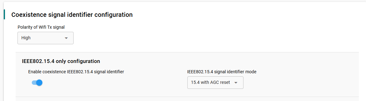
Polarity of Wi-Fi TX signal#
If set to high, Wi-Fi TX PAEN is detected as asserted when the GPIO pin is high (> Vih).
If set to low, Wi-Fi TX PAEN is detected as asserted when the GPIO pin is low (< Vil).
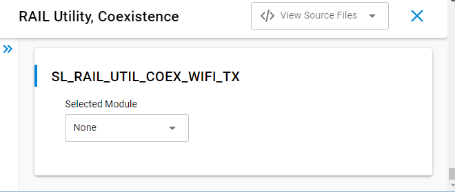
Wi-Fi TX signal GPIO port and GPIO pin#
Select Wi-Fi TX port and pin matching circuit board configuration.
To configure GPIO port and pin for the Wi-Fi TX signal in the Component Editor, use the SL_RAIL_UTIL_COEX_WIFI_TX section of the configuration header.
If configured, signal detector will be restarted when Wi-Fi TX is de-asserted
PWM#
PWM REQUEST signal (shared REQUEST only)
If REQUEST signal is NOT shared, PWM REQUEST signal must be set to “Disabled”.
If REQUEST signal is shared, the REQUEST GPIO pin is used to arbitrate REQUEST between multiple EFR32 radios and a second GPIO is required to drive REQUEST||PWM. PWM REQUEST signal specifies the REQUEST||PWM GPIO.
PWM REQUEST signal level (shared REQUEST only)
If PWM REQUEST signal is “Disabled”, then PWM REQUEST signal level selection is ignored. Else, PWM REQUEST signal is shared and implements open-drain or open-source I/O for multi-EFR32 radio applications.
If active low, PWM REQUEST is open-drain, an external 1 k ±5% pull-up is required, and PWM REQUEST GPIO pin is driven low (< Vol) when REQUEST||PWM is asserted.
If active high, PWM REQUEST is open-source, an external 1 k ±5% pull-down is required, and PWM REQUEST GPIO pin is driven high (> Voh) when REQUEST||PWM is asserted.
PWM REQUEST signal GPIO port and PWM REQUEST signal GPIO PIN#
To configure GPIO port and pin for the PWM REQUEST signal in the Component Editor, use the SL_RAIL_UTIL_COEX_PWM_REQ section of the configuration header.

Enable PWM REQUEST at startup#
If enabled, PWM REQUEST is enabled at firmware startup as per specified period, duty-cycle, and priority.
If not enabled, PWM REQUEST is disabled at firmware startup, but can be enabled via run-time API.
PWM REQUEST Period (0.5 ms)#
Note: PWM REQUEST Period selection cannot be an integer sub-multiple of the Wi-Fi beacon or a significant number of consecutive Wi-Fi beacons may be missed, causing AP to collapse Wi-Fi network or STA to disassociate. Silicon Labs achieves <1% 802.15.4 message receive loss with PWM REQUEST set to 39 ms (or 78 half-ms) period, 20% duty-cycle, and high priority, which results in ~30% reduction in Wi-Fi TCP throughput over MCS0 to MCS7 and 20 or 40 MHz bandwidth.
Sets PWM REQUEST Period from 5 ms (10) to 109 ms (218) in 0.5 ms steps.
PWM REQUEST Duty-Cycle (%)#
Note: Large PWM REQUEST Duty-Cycle selection will substantially impact the Wi-Fi throughput as it reserved more time for 802.15.4 listening. Silicon Labs achieves <1% 802.15.4 message receive loss with PWM REQUEST set to 39 ms (or 78 half-ms) period, 20% duty-cycle, and high priority, which results in ~30% reduction in Wi-Fi TCP throughput over MCS0 to MCS7 and 20 or 40 MHz bandwidth.
Sets PWM REQUEST Duty-Cycle from 1% to 95% in 1% steps.
Assert PRIORITY when PWM REQUEST asserted#
Sets PWM REQUEST PRIORITY to assert or not when PWM REQUEST asserts.
Radio Hold Off#
RHO (Radio Hold Off) signal enabled#
If selected, RHO is mapped to GPIO pin and is used by PTA implementation.
If not selected, RHO is not mapped to GPIO pin and RHO is always de-asserted.
RHO (Radio Hold Off) active high#
If selected, RHO is asserted when RHO GPIO pin is high (> Vih).
If not selected, RHO is asserted when RHO GPIO pin is low (< Vil).
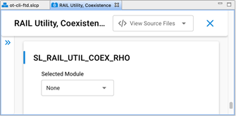
RHO (Radio Hold Off) signal GPIO port and RHO (Radio Hold Off) signal GPIO pin#
Select RHO port and pin matching circuit board configuration.
To configure GPIO port and pin for the RHO signal in the Component Editor, use the SL_RAIL_UTIL_COEX_RHO section of the configuration header.
Directional PRIORITY#
Enable Directional PRIORITY#
If True:
Directional PRIORITY signal is connected to the Wi-Fi PTA and multiplexes priority state and radio state information.
Allows the Wi-Fi PTA master to obtain radio state information from the EFR32 using the Directional PRIORITY signal.
When requesting network airtime, the EFR32 will assert a pulse on the Directional PRIORITY line depending on the requirement of that transaction and then switch to communicating the state of the radio on the same Directional PRIORITY line.
The Directional PRIORITY line is held low when the radio is in receive mode and is held high when the radio is in transmit mode.
The PRIORITY signal is not assigned a GPIO and is set to Disabled, has no physical connection to the Wi-Fi PTA and is used as Static PRIORITY input to the Directional PRIORITY logic block with the remaining PRIORITY signal configuration options described in PRIORITY applied.
Note: Hardware Configurator PRIORITY configuration fields are disabled and therefore not editable when Enable Directional PRIORITY is set to True. A workaround is to assign any GPIO to PRIORITY signal, edit the PRIORITY configuration options, and then set PRIORITY signal to Disabled.
If False:
The Directional PRIORITY signal is not used or connected to the Wi-Fi PTA.
The PRIORITY signal is connected to the Wi-Fi PATA and operates as Static PRIORITY and is either high or low during REQUEST asserted for the transmit or receive operation.
Directional PRIORITY Timer (Component Editor)#
To configure the Directional PRIORITY Timer in the Component Editor.
Use the SL_RAIL_UTIL_COEX_DP_TIMER to choose an unused timer.
Set the TIMER Compare/Capture Channel 0 (CC0) pin to match the same GPIO pin used for REQUEST.
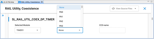
Note: For EFR32xG2x devices, the Timer Compare / Capture Channel is selected by the stack code. However, for EFR32xG1x devices, the stack code does not select the Timer Compare / Capture Channel pin.
Directional PRIORITY Pulse Width [0-255]#
Set to 20 (0x14) by default.
Selects the hold time of the Directional PRIORITY RX Priority pulse in microseconds for a range of 1 to 255 depending on the requirement of the Wi-Fi PTA. Silicon Labs recommends the default of 20 microseconds for typical Wi-Fi PTA implementations.
Set to 0 to bypass Directional PRIORITY.
Directional Priority PRS Channel#
To configure the Directional PRIORITY PRS Channel:
Choose any group of four PRS channels (EFR32xG2x) or five PRS channels (EFR32xG1x) not currently used by the SDK stack software, other plugins, or custom code.
Assign the highest PRS channel number from this group to the Directional Priority PRS Channel value.
Note: The External FEM plugin is recommended to be enabled for monitoring the EFR32 radio TX activity and radio RX activity for the custom coexistence application test and development purposes and can use up to two additional PRS channels.
The SDK stack software automatically selects the preceding three PRS channels from the group.
Example: For EFR32xG2x, the designer selects PRS channel 2 as the Directional Priority PRS Channel value. From the designer’s choice, the SDK stack software automatically selects PRS channel 1, PRS channel 0 and PRS channel 11 for use in the Directional Priority PRS Channel group. In this example, the SDK stack software automatically wraps around from the lowest PRS channel number to the highest PRS channel number until all three additional required PRS channels are assigned.
To configure the Directional PRIORITY PRS Channel in SSv5 Component Editor:
Use the SL_RAIL_UTIL_COEX_DP_OUT section of the configuration header.
Selecting the Directional PRIORITY PRS Channel displays the PRS Channel Output Pin configuration option.
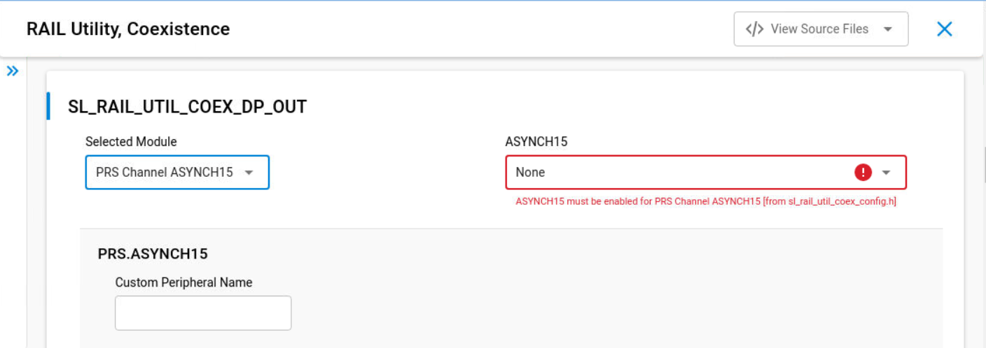
PRS Channel Output Pin#
Directional PRIORITY output GPIO pin
Connects to the Wi-Fi PTA
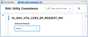
Inverted Request PRS Channel#
For EFR32xG2x Series 2 EFR32 devices, the Inverted Request PRS Channel is selected by the stack code. However, the stack code does not select the Inverted Request PRS Channel for EFR32xG1x Series 1 EFR32 devices.
Choose any PRS channel not used by the SDK stack software, other plugins, custom code, or the Directional Priority PRS Channel option.
For EFR32xG2x, leave this option Disabled.
To configure the Inverted Request PRS Channel in the Component Editor, use the SL_RAIL_UTIL_COEX_DP_REQUEST_INV section of the configuration header.
RX Active#
RX active signal enabled#
If selected, MODEM_FRAME_DETECT is mapped to GPIO pin using a PRS channel.
If not selected, MODEM_FRAME_DETECT is not mapped to GPIO pin and does not use a PRS channel.
RX active assert signal level#
Selecting High results in a high signal output when the receive packet is detected and a low output otherwise.
Selecting Low results in a low signal output when the receive packet is detected and a high output otherwise.
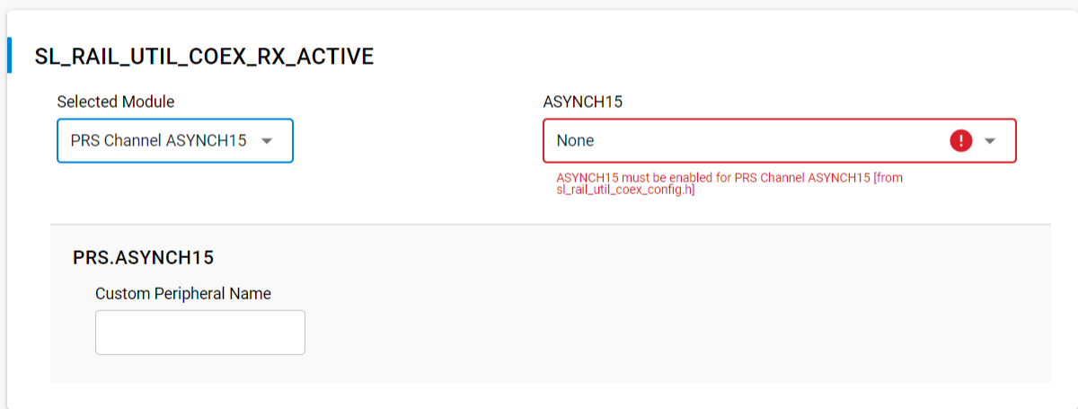
RX active PRS channel#
Selects PRS channel used to assign MODEM_FRAME_DETECT signal to an output GPIO.
PRS channel output pin#
Choose the GPIO to output the MODEM_FRAME_DETECT signal.
Notes:
The RX Active feature passes the 802.15.4 MODEM_FRAME_DETECT radio signal to a GPIO pin using a PRS channel.
To configure the GPIO port and pin in the Component Editor use the SL_RAIL_UTIL_COEX_RX_ACTIVE section of the configuration header as shown in the following figure.
This completes the Coexistence Configurator setup. When working in the Component Editor, the configurations are automatically saved and the generate step is not required. The coexistence configurations are saved in sl_rail_util_coex_config.h and sl_rail_util_coex_common_config.h.
Run-Time PTA Reconfiguration#
The following PTA options, which can be configured at compile time, can also be re-configured at run-time:
Receive retry timeout (milliseconds) [0-255]
Disable ACKing when GRANT de-asserted, RHO asserted, or REQUEST not secured (shared REQUEST only)
Abort transmission mid packet if GRANT is lost
TX high PRIORITY
RX high PRIORITY
REQUEST high PRIORITY on receive retry
Receive retry REQUEST enabled
RHO (Radio Hold Off) signal enabled
CCA/GRANT TX PRIORITY Escalation Threshold
MAC Fail TX PRIORITY Escalation Threshold
PWM REQUEST
The following PTA options cannot be configured during compile time and can only be configured at run-time:
Enable or disable PTA
Disable REQUEST (force holdoff)
Synch MAC to GRANT (MAC holdoff)
REQUEST/PRIORITY Assert (Preamble/Synch or Address Detection)
For descriptions of the above PTA options fields, see PTA Option Descriptions below.
For OpenThread using the Component Editor, the Synch MAC to GRANT (MAC holdoff) option has been added as a configuration option under the OpenThread Coexistence component so you can configure it at compile time. This requires that you have already installed the Coexistence component as a part of your project.
Note: For Silicon Labs OpenThread SDK releases prior to 1.2.0.0, the Synch MAC to GRANT (MAC holdoff) configuration option is available under the OpenThread Platform Abstraction component.
PTA Option Descriptions#
The descriptions of the above PTA options fields follow.
Disable REQUEST (force holdoff)#
If not set (default), REQUEST operates per the description in Wi-Fi Coexistence Fundamentals.
If set, REQUEST stays disabled, effectively halting all radio TX/RX functions.
Synch MAC to GRANT (MAC holdoff)#
If not set (default), Synch MAC to GRANT is disabled for 802.15.4-compliant random MAC delays.
If set, MAC CCA/TX is delayed until GRANT is asserted, synching all TX operations with GRANT.
Synch MAC to GRANT is not strictly 802.15.4 compliant as it prevents random MAC delay execution.
Synch MAC to GRANT should only be enabled during known, higher priority, Wi-Fi or BT interfering activity and disabled as soon as such activity completes.
REQUEST/PRIORITY Assert (Preamble/Synch or Address Detection)#
If set to 0 (00b, default and recommended):
REQUEST during RX is asserted at Preamble/Synch.
PRIORITY during RX is asserted at Preamble/Synch, as per “RX high PRIORITY” setting.
If set to 1 (01b) or 3 (11b) [requires “RX high PRIORITY” set to high priority (1)]:
REQUEST during RX is asserted at Address Detection (for this radio).
PRIORITY during RX is asserted at Address Detection (for this radio).
If set to 2 (10b) [requires “RX high PRIORITY” set to low priority (0)]:
REQUEST during RX is asserted at Preamble/Synch.
PRIORITY during RX is asserted at Address Detection (for this radio).
Notes:
For Zigbee, the API function calls for re-configuring coexistence PTA vary based on SoC or EZSP application.
For OpenThread, the API functions for re-configuring coexistence PTA is currently supported on SoC only.
For Run-Time API options not supported by selected EmberZNet PRO or OpenThread releases, the corresponding ptaOptions bit fields are RESERVED and must be written to 0.
SoC Application API (using Component Editor for Zigbee and OpenThread)#
To avoid warnings and errors at build time associated with the API function calls in this section, add the following # include into the application's <xxx>-callbacks.c file.
#include "platform/radio/rail_lib/plugin/coexistence/protocol/ieee802154_uc/coexistence-802154.h";The following two SoC API function calls enable and disable the PTA at run-time:
bool sl_rail_util_coex_is_enabled(void;
sl_status_t sl_rail_util_coex_set_enable(bool enabled);The following two SoC API function calls re-configure the PTA at run-time:
sl_rail_util_coex_options_t sl_rail_util_coex_get_options(void);
sl_status_t sl_rail_util_coex_set_options(sl_rail_util_coex_options_t options);Where sl_rail_util_coex_options_t is a uint32_t with the following bitmap definition.
PTA Feature | Bit Position | Size (bits) |
|---|---|---|
Receive retry timeout (milliseconds) [0-255] | 0 | 8 |
Disable ACKing when GRANT de-asserted, RHO asserted, or REQUEST not secured (shared REQUEST only) | 8 | 1 |
Abort transmission mid packet if GRANT is lost | 9 | 1 |
TX high PRIORITY | 10 | 1 |
RX high PRIORITY | 11 | 1 |
REQUEST high PRIORITY on receive retry | 12 | 1 |
RHO (Radio Hold Off) signal enabled | 14 | 1 |
Reserved (Reserved bits MUST be written 0) | 15 | 1 |
Disable REQUEST (force holdoff) | 16 | 1 |
Synch MAC to GRANT (MAC holdoff) | 17 | 1 |
REQUEST/PRIORITY Assert (Preamble/Synch or Address Detection) | 18 | 2 |
CCA/GRANT TX PRIORITY Escalation Threshold | 20 | 3 |
Reserved (Reserved bits MUST be written 0) | 23 | 2 |
MAC Fail TX PRIORITY Escalation Threshold | 25 | 2 |
Reserved (Reserved bits MUST be written 0) | 27 | 5 |
The following two SoC API function calls re-configure the PWM REQUEST at run-time:
const sl_rail_util_coex_pwm_args_t *sl_rail_util_coex_get_request_pwm_args(void);
sl_status_t sl_rail_util_coex_set_request_pwm (sl_rail_util_coex_req_t ptaReq,
sl_rail_util_coex_cb_t ptaCb, uint8_t dutyCycle, uint8_t periodHalfMs);Where sl_rail_util_coex_pwm_args_t is an alias for COEX_PwmArgs_t and:
typedef struct COEX_PwmArgs {
COEX_Req_t req;
uint8_t dutyCycle;
uint8_t periodHalfMs;
} COEX_PwmArgs_t;and
ptaReq/req: 0x00 => PWM REQUEST disabled
0x80 => PWM REQUEST enabled at low priority
0x82 => PWM REQUEST enabled at high priority
ptaCb: NULL
dutyCycle: PWM REQUEST duty-cycle from 5% to 95% in 1% steps
periodHalfMs: PWM REQUEST Period from 5 ms (10) to 109 ms (218) in 0.5 ms stepsThe following two SoC API function calls re-configure the Directional PRIORITY at run-time:
uint8_t sl_rail_util_coex_get_directional_priority_pulse_width(void);
sl_status_t sl_rail_util_coex_set_directional_priority_pulse_width(uint8_t pulseWidthUs);Where:
pulseWidthUs: Pulse width (0 to disable, 1-255µs)When multiple EFR32s are connected to Wi-Fi/PTA, TX PRIORITY Escalation can be controlled at run-time via "CCA/GRANT TX PRIORITY Escalation Threshold" and "MAC Fail TX PRIORITY Escalation Threshold" fields of PTA Options. When using this feature, "TX high PRIORITY" field must be set to 0 to avoid driving PRIORITY high on all TX messages.
Zigbee Network Coprocessor Application using EZSP API#
The following two EZSP (EmberZNet Serial Protocol) API function calls enable and disable the PTA, re-configure the PTA, and reconfigure the PWM REQUEST at run-time:
sl_status_t sl_zigbee_ezsp_get_value(sl_zigbee_ezsp_value_id_t valueId, uint8_t *valueLength, uint8_t *value)
sl_status_t sl_zigbee_af_set_ezsp_value(sl_zigbee_ezsp_value_id_t valueId, uint8_t valueLength, uint8_t *value, const char * valueName)```
Where valueId and valueLength have the following PTA related options.
:::custom-table{width=45,10,15%,30%}
| EZSP Value ID | Value | Length (bytes) | Description |
|---------------|-------|----------------|-------------|
| SL_ZIGBEE_EZSP_VALUE_ENABLE_PTA | 0x31 | 1 | Enable (1) or disable (0) packet traffic arbitration. |
| SL_ZIGBEE_EZSP_VALUE_PTA_OPTIONS | 0x32 | 4 | Set packet traffic arbitration (PTA) configuration options. |
| SL_ZIGBEE_EZSP_VALUE_PTA_PWM_OPTIONS | 0x35 | 3 | Configure PWM REQUEST options. |
| SL_ZIGBEE_EZSP_VALUE_PTA_DIRECTIONAL_PRIORITY_PULSE_WIDTH | 0x36 | 1 | Pulse width (0 to disable, 1-255µs) |
:::
Where PTA configuration options are a `uint32_t` with the following bitmap definition.
| PTA Feature | Bit Position | Size (bits) |
|-------------|--------------|-------------|
| Receive retry timeout (milliseconds) [0-255] | 0 | 8 |
| Disable ACKing when GRANT de-asserted, RHO asserted, or REQUEST not secured (shared REQUEST only) | 8 | 1 |
| Abort transmission mid packet if GRANT is lost | 9 | 1 |
| TX high PRIORITY | 10 | 1 |
| RX high PRIORITY | 11 | 1 |
| REQUEST high PRIORITY on receive retry | 12 | 1 |
| Receive retry REQUEST enabled | 13 | 1 |
| RHO (Radio Hold Off) signal enabled | 14 | 1 |
| Reserved (Reserved bits MUST be written 0) | 15 | 1 |
| Disable REQUEST (force holdoff) | 16 | 1 |
| Synch MAC to GRANT (MAC holdoff) | 17 | 1 |
| REQUEST/PRIORITY Assert (Preamble/Synch or Address Detection) | 18 | 2 |
| CCA/GRANT TX PRIORITY Escalation Threshold (requires additional application code) | 20 | 3 |
| Reserved (Reserved bits MUST be written 0) | 23 | 2 |
| MAC Fail TX PRIORITY Escalation Threshold (requires additional application code) | 25 | 2 |
| Reserved (Reserved bits MUST be written 0) | 27 | 5 |
PWM REQUEST configuration options is a three-byte uint8_t array:
```C
{uint8_t ptaReq, uint8_t dutyCycle, uint8_t periodHalfMs}Where:
ptaReq: 0x00 => PWM REQUEST disabled
0x80 => PWM REQUEST enabled at low priority
0x82 => PWM REQUEST enabled at high priority
dutyCycle: PWM REQUEST duty-cycle from 5% to 95% in 1% steps
periodHalfMs: PWM REQUEST Period from 5 ms (10) to 109 ms (218) in 0.5 ms stepsand the Directional PRIORITY parameter is:
uint8_t dp_pulse: Pulse width (0 to disable, 1-255µs)When multiple EFR32s are connected to Wi-Fi/PTA, TX PRIORITY Escalation can be controlled at run-time via "CCA/GRANT TX PRIORITY Escalation Threshold" and "MAC Fail TX PRIORITY Escalation Threshold" fields of PTA Options. When using this feature, "TX high PRIORITY" field must be set to 0 to avoid driving PRIORITY high on all TX messages.
Coexistence Configuration Setup Examples for Different Wi-Fi/PTA Applications (Zigbee)#
Example 1: Configure EFR32 PTA support to operate as single EFR32 with typical 3-Wire Wi-Fi/PTA#
Single EFR32 radio
RHO unused
REQUEST unshared, active high, PC10
Compatible 3-Wire Wi-Fi PTA devices sometimes refer to this signal as RF_ACTIVE or BT_ACTIVE (active high).
GRANT, active low, PF3
Compatible 3-Wire Wi-Fi PTA devices sometimes refer to this signal as WLAN_DENY (deny is active high, making grant active low).
PRIORITY, active high RX and TX (escalation disabled), PD12
Compatible 3-Wire W-Fi PTA devices sometimes refer to this signal as RF_STATUS or BT_STATUS (active high).
Note: PRIORITY is static, not directional. If operated with a 3-Wire PTA expecting directional:
Static high PRIORITY is interpreted as high PRIORITY and always in TX mode, regardless of actual TX or RX.
Static low PRIORITY is interpreted as low PRIORITY and always in RX mode, regardless of actual TX or RX.
PWM REQUEST disabled.
Other options enabled to maximize 802.15.4 performance:
802.15.4 RX and TX both at high priority
Receive retry REQUEST enabled with 16ms timeout and high priority.
Enabled ACKing when GRANT de-asserted.
The logic analyzer capture in the following figure shows the PTA interface, Wi-Fi radio state, and EFR32 radio state for an EFR32 radio configured for typical 3-Wire Wi-Fi/PTA.
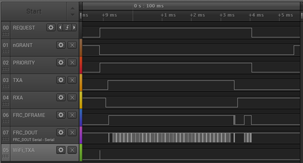
Where:
REQUEST: active high, push-pull REQUEST output
nGRANT: active low GRANT input
PRIORITY: active high PRIORITY output
TXA: EFR32 FEM TX Active control signal (configured via FEM Control plugin)
RXA: EFR32 FEM RX Active control signal (configured via FEM Control plugin)
FRC_DFRAME: EFR32 Frame Control Data Frame signal (packet trace frame/synch)
FRC_DOUT: EFR32 Frame Control Data Out signal (packet trace data)
WiFi_TXA: Wi-Fi TX Active signal
This logic analyzer sequence shows:
Wi-Fi starts a transmit but is immediately pre-empted (WiFi_TXA pulse) by higher priority 802.15.4 transmit asserting REQUEST and PRIORITY.
GRANT is asserted by Wi-Fi/PTA.
EFR32 radio completes CCA and CCA passes, and GRANT is asserted.
EFR32 radio proceeds with transmit (RXA de-asserts, followed by TXA assert).
After transmitting, EFR32 waits for ACK (TXA de-asserts, followed by RXA assert).
EFR32 receives ACK (second FRC_DFRAME pulse). <= 802.15.4 TX message successfully completed
EFR32 de-asserts PRIORITY and REQUEST.
Wi-Fi/PTA de-asserts GRANT.
Example 2: Configure EFR32 PTA support to operate with multi-radio 2-Wire Wi-Fi/PTA with active-low REQUEST#
Multiple EFR32 radios (external 1 k ±5% pull-up required on REQUEST)
RHO unused
REQUEST shared, active Low, PC10
GRANT, active Low, PF3
PRIORITY unused
PWM REQUEST disabled
Other option settings to maximize 802.15.4 performance:
Enable REQUEST to receive retry with 16ms timeout.
Do not Disable (Enable) ACKing when GRANT is de-asserted RHO asserted, REQUEST not secured.
The logic analyzer capture in the following figure shows the PTA interface, Wi-Fi radio state, and EFR32 radio state for an EFR32 radio configured for multi-radio 2-Wire PTA with active-low REQUEST:
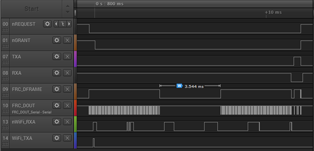
Where:
nREQUEST: active low, shared (open-drain) REQUEST input/output
nGRANT: active low GRANT input
TXA: EFR32 FEM TX Active control signal (configured via FEM Control plugin)
RXA: EFR32 FEM RX Active control signal (configured via FEM Control plugin)
FRC_DFRAME: EFR32 Frame Control Data Frame signal (packet trace frame/synch)
FRC_DOUT: EFR32 Frame Control Data Out signal (packet trace data)
nWiFi_RXA: Wi-Fi RX Active signal
WiFi_TXA: Wi-Fi TX Active signal
This logic analyzer sequence shows:
802.15.4 packet is detected (FRC_DFRAME asserted) while Wi-Fi is receiving a packet (nWiFi_RXA asserted).
Shared REQUEST signal is tested and found not asserted by another EFR32 radio, so receiving EFR32 radio asserts REQUEST.
Wi-Fi ACK is transmitted (WiFi-TXA asserted) during 802.15.4 receive (no Wi-Fi TX pre-emption or higher priority Wi-Fi activity).
After Wi-Fi ACK completes, GRANT is asserted by Wi-Fi/PTA.
802.15.4 receive is completed but CRC failed as packet was corrupted by co-located Wi-Fi ACK transmit during receive.
Since PTA configured with Receive retry REQUEST enabled using 16ms timeout, REQUEST is held up to 16ms for 802.15.4 retry with 2.4 GHz quiet (Wi-Fi held off).
Wi-Fi continues to receive packets (nWiFi_RXA asserts) but does not ACK while 802.15.4 radio has GRANT.
After 3.5 ms gap for end-node ACK timeout and MAC random delay, the 802.15.4 retry packet arrives and is received without error.
802.15 ACK is transmitted (TXA asserted). <= 802.15.4 RX message successfully completed.
After 802.15.4 ACK completes, REQUEST is de-asserted, followed by GRANT de-assert.
Example 3: Configure EFR32 PTA support to operate with multi-radio typical 3-Wire Wi-Fi/PTA#
Multiple EFR32 radios (external 1 k ±5% pull-down required on REQUEST and external 1 k ±5% pull-down required on PRIORITY)
RHO unused
REQUEST shared, active High, PC10
GRANT, active Low, PF3
PRIORITY shared, active high RX and TX (escalation disabled), PD12
PWM REQUEST disabled
Other option settings to maximize 802.15.4 performance:
Enable REQUEST to receive retry with 16ms timeout.
Do not Disable (Enable) ACKing when GRANT is de-asserted RHO asserted, REQUEST not secured.