Series 2 DCI and SWD Programming Examples#
The programming examples in this application note use the Series 2 DCI and SWD Programming platform example of GSDK v4.0.1. The hardware and software implementation may be different on other versions of the GSDK.
For more information about production programming steps, see section "Overview" in Production Programming of Series 2 and Series 3 Devices.
Hardware Overview#
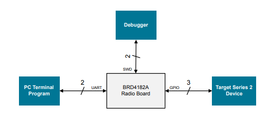
The Wireless Starter Kit (WSTK) with the BRD4182A Radio Board (EFR32MG22C224F512IM40) is used as the hardware platform of the DCI and SWD programmer.
The programmer uses GPIO to emulate the DCI and SWD to program the target device. The UART interface handles the user interface. The VCOM_TX and VCOM_RX are routed to the WSTK virtual COM port by setting the VCOM_ENABLE line high.
Resources of BRD4182A Used by Programmer
GPIO (SoC Peripheral) | WSTK Peripheral | Function | EXP Header Connection |
|---|---|---|---|
PA01 (DBG_SWCLK) | DBG_TCK_SWCLK | Programmer debug SWCLK | — |
PA02 (DBG_SWDIO) | DBG_TCK_SWDIO | Programmer debug SWDIO | — |
PA05 (US1_TX) | VCOM_TX | WSTK Virtual COM port TX | Pin 12 |
PA06 (US1_RX) | VCOM_RX | WSTK Virtual COM port RX | Pin 14 |
PB04 | VCOM_ENABLE | WSTK Virtual COM port enable | — |
PC03 | — | Target device RESETn | Pin 10 |
PD02 | UIF_LED0 | Target device SWCLK (shared with WSTK LED0) | Pin 11 |
PD03 | UIF_LED1 | Target device SWDIO (shared with WSTK LED1) | Pin 13 |
The following figure shows the interconnection between programmer and target device. The programmer is the WSTK with the BRD4182A Radio Board and the target device is the WSTK with one of the Series 2 radio boards below.
EFR32MG21A — BRD4181A (J101 P16 for SWCLK)
EFR32MG21B — BRD4181C (J101 P16 for SWCLK)
EFR32MG22 — BRD4182A (J101 P16 for SWCLK)
EFR32FG23A — BRD4263B (J101 P20 for SWCLK)
EFR32FG23B — BRD4263C (J101 P20 for SWCLK)
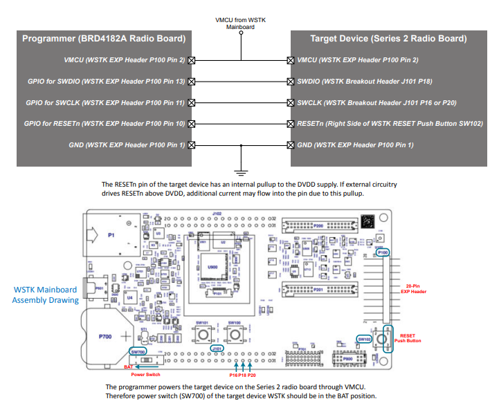
The programmer powers the target device on the Series 2 radio board through VMCU. Therefore power switch (SW700) of the target device WSTK should be in the BAT position.
Programmer Connection Diagram
The programmer can work on other Series 2 radio boards or kits. However, the following limitations may apply.
Some firmware images (
xg2*_app_image[] and xg2*_signed_imag[]) in Hard-coded Firmware Images are hardware-dependent (GPIOs for LEDs, push buttons, and UART). Therefore, they may not function properly on other radio boards or kits.The SWCLK and SWDIO of the target radio boards or kits may be on different pins or connectors. Therefore, the connection diagram above may not apply (refer to the board-specific schematics for details).
Software Overview#
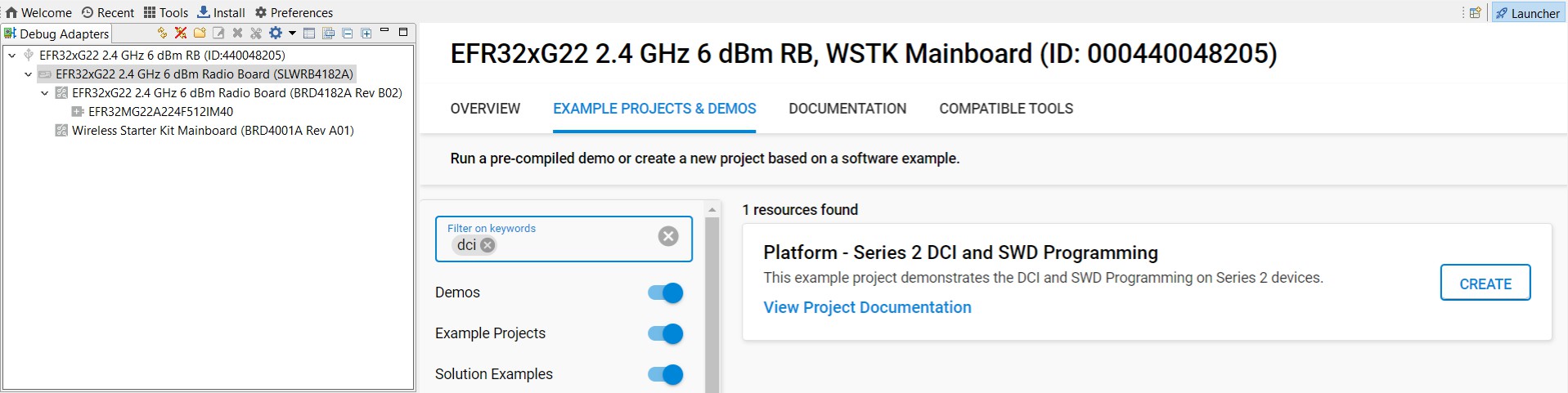
Users must select the BRD4182A radio board to access the Series 2 DCI and SWD Programming platform example in Simplicity Studio 5. Click the View Project Documentation link to open the readme file. This file includes the procedures to create the project and run the example.
Bit-Bang#
The main overhead on writing directly to MSC registers is to emulate the SWCLK and SWDIO signals by bit-banging GPIO pins. The programmer must use the GPIOs in the same port group (0-7 or 8-15) for SWCLK and SWDIO to speed up this emulation process. The software writes to the entire port at once when bit-banging the SWCLK and SWDIO signals. Therefore, the programmer cannot use the spare pins of this port for other purposes.
Security Keys#
The following table describes the security keys (hard-coded in app_dci_task.c) used in the programming examples. Users can modify these keys to adapt to the application requirements. The files (.prv and .pem) of security keys can be found in the Windows folder C:\SiliconLabs\SimplicityStudio\v5\developer\adapter_packs\secmgr\scripts\offline.
Hard-Coded Security Keys
Array | Usage | Source |
|---|---|---|
aes_key[] | Decrypt GBL payloads | A 16 bytes AES-128 key in encrypt-unsafe-key.prv (binary file). |
public_sign_key[] | Secure boot | A 64 bytes Public Sign Key, the corresponding Private Sign Key in root-sign-unsafe-privkey.pem. |
public_command_key[] | Secure debug unlock and Disable tamper | A 64 bytes Public Command Key, the corresponding Private Command Key in cmd-unsafe-privkey.pem. |
The public key can be derived from the private key by using OpenSSL.
openssl ec -in rootsign-unsafe-privkey.pem -pubout -text > public_sign_key.txtopenssl ec -in cmd-unsafe-privkey.pem -pubout -text > public_command_key.txtOTP Settings#
The following table describes the OTP settings (hard-coded in app_dci_task.c) used in the programming examples. Users can modify these values to adapt to the application requirements.
Hard-Coded OTP Settings
Array | OTP Settings | Value |
|---|---|---|
vse_svm_conf[] | VSE-SVM | MCU flags: Secure boot enable and Secure boot anti-rollback (0x00050000) |
hse_svm_conf[] | HSE-SVM | MCU flags: Secure boot enable and Secure boot anti-rollback (0x00050000) |
" | " | Reserved: 0x00000000, 0x00000000, 0x00000000, 0x00000000 |
hse_svh_xg21b_conf[] | HSE-SVH (xG21B) | MCU flags: Secure boot enable and Secure boot anti-rollback (0x00050000) |
" | " | Tamper source levels: 0x40440410, 0x14040104, 0x77442211, 0x42042224 |
" | " | Filter reset period: 10 |
" | " | Filter trigger threshold: 6 |
" | " | Tamper flags: 0 |
" | " | Tamper reset threshold: 5 |
hse_svh_other_conf[] | HSE-SVH (others) | MCU flags: Secure boot enable and Secure boot anti-rollback (0x00050000) |
" | " | Tamper source levels: 0x40440410, 0x14040104, 0x22414224, 0x74422112 |
" | " | Filter reset period: 10 |
" | " | Filter trigger threshold: 6 |
" | " | Tamper flags: 0 |
" | " | Tamper reset threshold: 5 |
Note: Refer to the tables below for details about OTP settings.
Firmware images#
The following table describes the firmware images (hard-coded in app_firmware_image.c) used in the programming examples. Users can modify these images to adapt to the application requirements.
Hard-Coded Firmware Images
Array | Size (Bytes) | Usage |
|---|---|---|
xg21_hse_image[] | 41125 | The xG21 HSE upgrade firmware image (v1.2.9) |
xg21_app_image[] | 9212 | The xG21 application firmware image (Blink Bare-metal platform example) |
xg21_signed_image[] | 11192 | A signed xG21 UART XMODEM Bootloader image (v1.12.0) |
erase_xg21_userdata[] | 3068 | Application firmware image to erase xG21 user data |
write_xg21_userdata[] | 4228 | Application firmware image to program xG21 user data |
prog_xg21_hse_upgrade[] | 6956 | Application firmware image to upgrade xG21 HSE firmware |
xg22_vse_image[] | 16549 | The xG22 VSE upgrade firmware image (v1.2.7) |
xg22_app_image[] | 10756 | The xG22 application firmware image (Blink Bare-metal platform example) |
xg22_signed_image[] | 14128 | A signed xG22 UART XMODEM Bootloader image (v1.12.0) |
prog_xg22_vse_upgrade[] | 9320 | Application firmware image to upgrade xG22 VSE firmware |
xg23_hse_image[] | 88221 | The xG23 HSE upgrade firmware image (v2.1.4) |
xg23_app_image[] | 13560 | The xG23 application firmware image (Blink Bare-metal platform example) |
xg23_signed_image[] | 16248 | A signed xG23 UART XMODEM Bootloader image (v1.12.0) |
prog_xg23_hse_upgrade[] | 11696 | Application firmware image to upgrade xG23 HSE firmware |
Note:
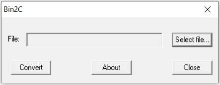
The HSE or VSE upgrade firmware image must be stored to the device's internal flash in .seu format.
The firmware image (
.seuformat) can be converted to a C source file using the SEGGER free utilityBin2C.exe. The last NULL (0x00) character in the converted firmware image array should be discarded.
The programmer uses the bootloader image signed by the Private Sign Key (rootsign-unsafe-privkey.pem) to recover a secure boot failure device.
Refer to Add a New Series Device to the Programmer for instructions on adding firmware images for newer devices.
Compile Options#
The following tables describe the compile options in header files to set up the software and hardware environment for the programming examples.
Compile Options in app_dci_swd.h
Parameter | Usage | Default Setting |
|---|---|---|
RESET_PULSE | Pin reset pulse width in microseconds | 1000 µs (1 ms) |
RESET_DELAY | Delay in microseconds after issuing a soft or pin reset | 50000 µs (50 ms) |
DCI_RETRY_COUNT | Number of times to retry a DCI read or write operation. It must be high enough to receive a response from the SE command. | 1001000 |
SWCLK_PORT | GPIO port for SWCLK | 3 (Port D) |
SWCLK_PIN | GPIO pin for SWCLK | 2 (PD02) |
SWDIO_PORT | GPIO port for SWDIO | 3 (Port D) |
SWDIO_PIN | GPIO pin for SWDIO | 3 (PD03) |
RESET_PORT | GPIO port for RESETn | 2 (Port C) |
RESET_PIN | GPIO pin for RESETn | 3 (PC03) |
Compile Options in app_firmware_image.h
Parameter | Usage | Default Setting |
|---|---|---|
SE_START_ADDR | SE upgrade firmware image start address (aligned with 8 kB flash page size) | 0x00060000 |
SE_UPGRADE_DELAY | Delay in microseconds after issuing a command to upgrade the SE firmware | 2500000 µs (2.5 s) |
USER_DATA_DELAY | Delay in microseconds after issuing a soft reset to run the application to erase or write the user data on xG21 devices | 1000000 µs (1 s) |
Note: Make sure the device has enough flash space to accommodate the SE firmware image when setting the SE_START_ADDR.
Compile Options in app_swd_task.h
Parameter | Usage | Default Setting |
|---|---|---|
ERASE_DELAY | Delay in microseconds after a flash page erase or mass erase | 12000 µs (12 ms) |
ERASE_LOOPCNT | It must be high enough to cover the page erase or mass erase time | 1000 |
SKIP_POLLING | Skip polling WDATAREADY bit in the MSC STATUS register after writing 32-bit word to target device flash | 1 (Skip) |
WRITE_DELAY | Fix delay in microseconds after writing a 32-bit word to target device flash (if SKIP_POLLING = 1) | 11 µs |
Note:
Refer to Flash Erase for details about page erase and mass erase.
Refer to Flash Write for details about
SKIP_POLLINGandWRITE_DELAY.
Menu Operation
The SPACE and ENTER presses from the terminal program are used to manipulate the menu of the programmer.
Interface Menu
Series 2 DCI and SWD Programming Examples - Core running at 80000 kHz.
. Current interface selection is DEBUG CHALLENGE INTERFACE (DCI).
+ Press SPACE to pick an interface (DCI/SWD), press ENTER to select the task of the chosen interface.DCI Menu
. Current DCI task is GET SE STATUS.
+ Press SPACE to cycle through the DCI tasks, press ENTER to run the selected DCI task.
+ Current DCI task is READ SE OTP CONFIGURATION.
+ Current DCI task is READ SERIAL NUMBER.
+ Current DCI task is READ PUBLIC SIGN KEY.
+ Current DCI task is READ PUBLIC COMMAND KEY.
+ Current DCI task is READ LOCK STATUS.
+ Current DCI task is SET DEBUG RESTRICTIONS.
+ Current DCI task is ENABLE SECURE DEBUG.
+ Current DCI task is DISABLE SECURE DEBUG.
+ Current DCI task is LOCK DEVICE.
+ Current DCI task is ERASE DEVICE (UNLOCK).
+ Current DCI task is RECOVER SECURE BOOT FAILURE DEVICE.
+ Current DCI task is UPGRADE SE FIRMWARE THROUGH DCI.
+ Current DCI task is INITIALIZE AES-128 KEY (HSE).
+ Current DCI task is INITIALIZE PUBLIC SIGN KEY.
+ Current DCI task is INITIALIZE PUBLIC COMMAND KEY.
+ Current DCI task is INITIALIZE SE OTP.
+ Current DCI task is DISABLE DEVICE ERASE.From task ENABLE SECURE DEBUG to task UPGRADE SE FIRMWARE THROUGH DCI:
+ Current DCI task is ENABLE SECURE DEBUG.
+ Press ENTER to confirm or press SPACE to abort.From task INITIALIZE AES-128 KEY (HSE) to task DISABLE DEVICE ERASE:
+ Current DCI task is DISABLE DEVICE ERASE.
+ Warning: This is a ONE-TIME command and the operation is IRREVERSIBLE!
+ Press ENTER to confirm or press SPACE to abort.SWD Interface Menu
Series 2 DCI and SWD Programming Examples - Core running at 80000 kHz.
. Current interface selection is DEBUG CHALLENGE INTERFACE (DCI).
+ Press SPACE to pick an interface (DCI/SWD), press ENTER to select the task of the chosen interface.
+ Current interface selection is SERIAL WIRE DEBUG (SWD) INTERFACE.
. Current SWD task is ERASE MAIN FLASH.
+ Press SPACE to cycle through the SWD tasks, press ENTER to run the selected SWD task.
+ Current SWD task is PROGRAM MAIN FLASH.
+ Current SWD task is ERASE USER DATA.
+ Current SWD task is PROGRAM USER DATA.
+ Current SWD task is UPGRADE SE FIRMWARE THROUGH APPLICATION FIRMWARE. + Current SWD task is ERASE MAIN FLASH.
+ Press ENTER to confirm or press SPACE to abort.Error Handling
+ Press ENTER to issue a pin reset to the target, press SPACE to skip.DCI Programming Examples#
The following DCI programming examples are based on EFR32MG21B (BRD4181C) as the target device Programmer Connection Diagram on page 23. Software is compiled with -O2 optimization in Simplicity IDE of Simplicity Studio 5.
Get SE Status
To get the current SE status.
. Current DCI task is GET SE STATUS.
+ Press SPACE to cycle through the DCI tasks, press ENTER to run the selected DCI task.
. Read target device SE status... OK
+ SE firmware version : 00010209
+ MCU firmware version : NA
+ Debug lock : Disabled
+ Debug lock state : False
+ Device Erase : Enabled
+ Secure debug : Disabled
+ Secure boot : Disabled
+ Boot status : 0x20 - Command successful.Read SE OTP Configuration#
To read the current SE OTP configuration.
. Current DCI task is READ SE OTP CONFIGURATION. + Press SPACE to cycle through the DCI tasks, press ENTER to run the selected DCI task. . Read target device user (SE OTP) configuration... OK + Secure boot : Disabled + Secure boot verify certificate : Disabled + Secure boot anti-rollback : Disabled + Secure boot page lock narrow : Disabled + Secure boot page lock full : Disabled + Tamper source level Filter counter : 1 SE watchdog : 4 SE RAM CRC : 4 SE hard fault : 4 SE software assertion : 4 SE secure boot : 4 User secure boot : 0 Mailbox authorization : 1 DCI authorization : 0 OTP read : 4 Self test : 4 TRNG monitor : 1 PRS0 : 1 PRS1 : 1 PRS2 : 2 PRS3 : 2 PRS4 : 4 PRS5 : 4 PRS6 : 7 PRS7 : 7 Decouple BOD : 4 Temperature sensor : 2 Voltage glitch falling : 2 Voltage glitch rising : 2 Secure lock : 4 SE debug : 0 Digital glitch : 2 SE ICACHE : 4 + Reset period for the tamper filter counter: ~32 ms x 1024 + Activation threshold for the tamper filter: 4 + Digital glitch detector always on: Disabled + Tamper reset threshold: 5SE will return the SE_RESPONSE_INVALID_COMMAND code if the SE OTP data has not been initialized or SE firmware version is less than v1.2.2 (xG21 or xG22 devices).
. Read target device user (SE OTP) configuration... Failed - Unsupported command.
+ Press ENTER to issue a pin reset to the target, press SPACE to skip.Read Serial Number
To read the serial number of the Series 2 device.
. Current DCI task is READ SERIAL NUMBER.
+ Press SPACE to cycle through the DCI tasks, press ENTER to run the selected DCI task.
. Read target device serial number... OK
+ The serial number (16 bytes): 000000000000000014B457FFFE0F77CERead Public Sign Key#
To read the Public Sign Key in SE OTP.
. Current DCI task is READ PUBLIC COMMAND KEY.
+ Press SPACE to cycle through the DCI tasks, press ENTER to run the selected DCI task.
. Read target device public command key... OK
+ The public command key (64 bytes): B1BC6F6FA56640ED522B2EE0F5B3CF7E5D48F60BE8148F0DC08440F0A4E1DCA4
7C04119ED6A1BE31B7707E5F9D001A659A051003E95E1B936F05C37EA793AD63SE will return the SE_RESPONSE_INTERNAL_ERROR code if the Public Sign Key has not been provisioned.
. Read target device public command key... Failed - Internal SE error.
+ Press ENTER to issue a pin reset to the target, press SPACE to skip.Read Public Command Key
To read the Public Command Key in SE OTP.
. Current DCI task is READ PUBLIC COMMAND KEY.
+ Press SPACE to cycle through the DCI tasks, press ENTER to run the selected DCI task.
. Read target device public command key... OK
+ The public command key (64 bytes): B1BC6F6FA56640ED522B2EE0F5B3CF7E5D48F60BE8148F0DC08440F0A4E1DCA4
7C04119ED6A1BE31B7707E5F9D001A659A051003E95E1B936F05C37EA793AD63SE will return the SE_RESPONSE_INTERNAL_ERROR code if the Public Command Key has not been provisioned.
. Read target device public command key... Failed - Internal SE error.
+ Press ENTER to issue a pin reset to the target, press SPACE to skip.Read Lock Status
To read the lock state of the debug port.
+ Current DCI task is READ LOCK STATUS.
. Debug port lock state
+ Debug Locked, config status : Disabled.
+ Device erase : Enabled.
+ Secure debug unlock : Enabled.
+ Debug port : Unlocked.
+ Invasive Debug Lock : Unlocked.
+ Non-invasive Debug Lock : Unlocked.
+ Secure Invasive Debug Lock : Unlocked.
+ Secure Non-invasive Debug Lock : Unlocked.Set Debug Restrictions
To set debug restrictions.
+ Setting the lockbit for Secure, Non-Invasive Debug
. Set the debug restriction bits of the target device... OK
. Read target device SE status... OK
+ SE firmware version : 0001020E
+ MCU firmware version : NA
+ Debug lock : Disabled
+ Debug lock state : False
+ Device Erase : Enabled
+ Secure debug : Enabled
+ Secure boot : Disabled and SE OTP is not configured
+ Boot status : 0x20 - Command successful.
Series 2 DCI and SWD Programming Examples - Core running at 80000 kHz.
. Current interface selection is DEBUG CHALLENGE INTERFACE (DCI).
+ Press SPACE to pick an interface (DCI/SWD), press ENTER to select the task of the chosen interface.Enable Secure Debug#
To enable the secure debug functionality.
+ Current DCI task is ENABLE SECURE DEBUG.
+ Press ENTER to confirm or press SPACE to abort.
. Enable secure debug of the target device... OK
. Read target device SE status... OK
+ SE firmware version : 00010209
+ MCU firmware version : NA
+ Debug lock : Disabled
+ Debug lock state : False
+ Device Erase : Enabled
+ Secure debug : Enabled
+ Secure boot : Disabled
+ Boot status : 0x20 - Command successful.SE will return the SE_RESPONSE_INVALID_PARAMETER code if the Public Command Key has not been provisioned.
. Enable secure debug of the target device... Failed - Parameters are invalid or buffer is too small.
+ Press ENTER to issue a pin reset to the target, press SPACE to skip.SE will return the SE_RESPONSE_INVALID_COMMAND code if the secure debug has already enabled.
. Enable secure debug of the target device... Failed - Unsupported command.
+ Press ENTER to issue a pin reset to the target, press SPACE to skip.Disable Secure Debug
To disable the secure debug functionality.
+ Current DCI task is DISABLE SECURE DEBUG.
+ Press ENTER to confirm or press SPACE to abort.
. Disable secure debug of the target device... OK
. Read target device SE status... OK
+ SE firmware version : 00010209
+ MCU firmware version : NA
+ Debug lock : Disabled
+ Debug lock state : False
+ Device Erase : Enabled
+ Secure debug : Disabled
+ Secure boot : Disabled
+ Boot status : 0x20 - Command successful.Lock Device
To enable the debug lock of the Series 2 device.
+ Current DCI task is LOCK DEVICE.
+ Press ENTER to confirm or press SPACE to abort.
. Lock target device... OK
. Read target device SE status... OK
+ SE firmware version : 00010209
+ MCU firmware version : NA
+ Debug lock : Enabled
+ Debug lock state : True
+ Device Erase : Enabled
+ Secure debug : Disabled
+ Secure boot : Disabled
+ Boot status : 0x20 - Command successful.Erase Device (Unlock)
To perform a device mass erase and unlock the standard debug lock of the Series 2 device.
+ Current DCI task is ERASE DEVICE (UNLOCK).
+ Press ENTER to confirm or press SPACE to abort.
. Erase (unlock) target device... OK
. Read target device SE status... OK
+ SE firmware version : 00010209
+ MCU firmware version : NA
+ Debug lock : Disabled
+ Debug lock state : False
+ Device Erase : Enabled
+ Secure debug : Disabled
+ Secure boot : Disabled
+ Boot status : 0x20 - Command successful.SE will return the SE_RESPONSE_INVALID_COMMAND code if the Device Erase is disabled.
. Erase (unlock) target device... Failed - Unsupported command.
+ Press ENTER to issue a pin reset to the target, press SPACE to skip.Recover Secure Boot Failure Device
To get the current SE status.
. Current DCI task is GET SE STATUS.
+ Press SPACE to cycle through the DCI tasks, press ENTER to run the selected DCI task.
. Read target device SE status... OK
+ SE firmware version : 00010209
+ MCU firmware version : NA
+ Debug lock : Disabled
+ Debug lock state : False
+ Device Erase : Enabled
+ Secure debug : Disabled
+ Secure boot : Enabled
+ Boot status : 0x14 - Failure while checking the host for secure boot.Issue a device erase to unlock the target device through DCI.
+ Current DCI task is RECOVER SECURE BOOT FAILURE DEVICE.
+ Press ENTER to confirm or press SPACE to abort.
. Issue a device erase through DCI.
+ Erase target device... OKA correctly-signed firmware image xg21_signed_image[] is programmed to the target device main flash through the SWD interface to recover a secure boot failure device.
+ Initialize DP... OK - IDCODE = 0x6BA02477
+ Read AP... OK - IDR = 0x84770001
+ Set up AHB-AP and halt target... OK
+ Get device information... OK - Target device is EFR32MG21B010F1024 and unique ID is 0x14B457FFFE0F7762
. Program a correctly-signed image to recover device.
+ The xG21 signed firmware image size is 11192 bytes and start address is 0x00000000.
+ Erase-Program-Verify the xG21 main flash for signed firmware image... OK (cycles: 13616519 time: 170 ms)
. Read target device SE status... OK
+ SE firmware version : 00010209
+ MCU firmware version : 010C0000
+ Debug lock : Disabled
+ Debug lock state : False
+ Device Erase : Enabled
+ Secure debug : Disabled
+ Secure boot : Enabled
+ Boot status : 0x20 - Command successful.The device cannot be recovered if the image is not correctly-signed.
. Read target device SE status... OK
+ SE firmware version : 00010209
+ MCU firmware version : 010C0000
+ Debug lock : Disabled
+ Debug lock state : False
+ Device Erase : Enabled
+ Secure debug : Disabled
+ Secure boot : Enabled
+ Boot status : 0x12 - Failure while checking the host for secure boot.Upgrade SE Firmware Through DCI
A SE upgrade firmware image xg21_hse_image[] is programmed to the target device main flash at SE_START_ADDR through the SWD interface. It will overwrite the data from
SE_START_ADDRtoSE_START_ADDR+ the size ofxg21_hse_image[].
+ Current DCI task is UPGRADE SE FIRMWARE THROUGH DCI.
+ Press ENTER to confirm or press SPACE to abort.
. Program a SE firmware image to the target device.
+ Initialize DP... OK - IDCODE = 0x6BA02477
+ Read AP... OK - IDR = 0x84770001
+ Set up AHB-AP and halt target... OK
+ Get device information... OK - Target device is EFR32MG21B010F1024 and unique ID is 0x588E81FFFE7034E5
+ The xG21 HSE firmware image version: 00010209
+ The xG21 HSE firmware image size is 41125 bytes and start address is 0x00060000.
+ Erase-Program-Verify the xG21 main flash for HSE firmware image... OK (cycles: 52365323 time: 654 ms) . Validate SE firmware image in the target device... OK
. Upgrade SE firmware image, delay few seconds to check SE status... Done
. Read target device SE status... OK
+ SE firmware version : 00010209
+ MCU firmware version : NA
+ Debug lock : Disabled
+ Debug lock state : False
+ Device Erase : Enabled
+ Secure debug : Disabled
+ Secure boot : Disabled
+ Boot status : 0x20 - Command successful.SE will return the SE_RESPONSE_INVALID_PARAMETER code if the SE upgrade firmware image is invalid.
. Validate SE firmware image in the target device... Failed - Parameters are invalid or buffer is too small.
+ Press ENTER to issue a pin reset to the target, press SPACE to skip.SE will return the SE_RESPONSE_INVALID_COMMAND code if the current SE firmware version is less than v1.2.2 (xG21 or xG22 devices).
. Validate SE firmware image in the target device... Failed - Unsupported command.
+ Press ENTER to issue a pin reset to the target, press SPACE to skip.
Initialize AES-128 Key (HSE)#
To initialize the aes_key[] to HSE OTP.
+ Current DCI task is INITIALIZE AES-128 KEY (HSE).
+ Warning: This is a ONE-TIME command and the operation is IRREVERSIBLE!
+ Press ENTER to confirm or press SPACE to abort.
. Initialize AES-128 key of the target device... OKSE will return the SE_RESPONSE_INVALID_PARAMETER code if the AES-128 key has already been initialized.
. Initialize AES-128 key of the target device... Failed - Parameters are invalid or buffer is too small.
+ Press ENTER to issue a pin reset to the target, press SPACE to skip.Initialize Public Sign Key
To initialize the public_sign_key[] to SE OTP.
+ Current DCI task is INITIALIZE PUBLIC SIGN KEY.
+ Warning: This is a ONE-TIME command and the operation is IRREVERSIBLE!
+ Press ENTER to confirm or press SPACE to abort.
. Initialize public sign key of the target device... OK
. Read target device public sign key... OK
+ The public sign key (64 bytes): C4AF4AC69AAB9512DB50F7A26AE5B4801183D85417E729A56DA974F4E08A562C
DE6019DEA9411332DC1A743372D170B436238A34597C410EA177024DE20FC819SE will return the SE_RESPONSE_INVALID_PARAMETER code if the Public Sign Key has already been initialized.
. Initialize public sign key of the target device... Failed - Parameters are invalid or buffer is too small.
+ Press ENTER to issue a pin reset to the target, press SPACE to skip.Initialize Public Command Key
To initialize the public_command_key[] to SE OTP.
+ Current DCI task is INITIALIZE PUBLIC COMMAND KEY.
+ Warning: This is a ONE-TIME command and the operation is IRREVERSIBLE!
+ Press ENTER to confirm or press SPACE to abort.
. Initialize public command key of the target device... OK
. Read target device public command key... OK
+ The public command key (64 bytes): B1BC6F6FA56640ED522B2EE0F5B3CF7E5D48F60BE8148F0DC08440F0A4E1DCA4
7C04119ED6A1BE31B7707E5F9D001A659A051003E95E1B936F05C37EA793AD63SE will return the SE_RESPONSE_INVALID_PARAMETER code if the Public Command Key has already been initialized.
. Initialize public command key of the target device... Failed - Parameters are invalid or buffer is too small.
+ Press ENTER to issue a pin reset to the target, press SPACE to skip.Initialize SE OTP#
To initialize the hse_svh_xg21b_conf[] to the HSE OTP.
+ Current DCI task is INITIALIZE SE OTP.
+ Warning: This is a ONE-TIME command and the operation is IRREVERSIBLE!
+ Press ENTER to confirm or press SPACE to abort.
. Initialize SE OTP of the target device... OK
. Read target device user (SE OTP) configuration... OK
+ Secure boot : Enabled
+ Secure boot verify certificate : Disabled
+ Secure boot anti-rollback : Enabled
+ Secure boot page lock narrow : Disabled
+ Secure boot page lock full : Disabled
+ Tamper source level
Filter counter : 1
SE watchdog : 4
SE RAM CRC : 4
SE hard fault : 4
SE software assertion : 4
SE secure boot : 4
User secure boot : 0
Mailbox authorization : 1
DCI authorization : 0
OTP read : 4
Self test : 4
TRNG monitor : 1
PRS0 : 1
PRS1 : 1
PRS2 : 2
PRS3 : 2
PRS4 : 4
PRS5 : 4
PRS6 : 7
PRS7 : 7
Decouple BOD : 4
Temperature sensor : 2
Voltage glitch falling : 2
Voltage glitch rising : 2
Secure lock : 4
SE debug : 0
Digital glitch : 2
SE ICACHE : 4
+ Reset period for the tamper filter counter: ~32 ms x 1024
+ Activation threshold for the tamper filter: 4
+ Digital glitch detector always on: Disabled
+ Tamper reset threshold: 5SE will return the SE_RESPONSE_INVALID_COMMAND code if the SE OTP has already programmed.
. Initialize SE OTP of the target device... Failed - Unsupported command.
+ Press ENTER to issue a pin reset to the target, press SPACE to skip.SE will return the SE_RESPONSE_INVALID_PARAMETER code if secure boot option is enabled and the Public Sign Key has not been provisioned.
. Initialize SE OTP of the target device... Failed - Parameters are invalid or buffer is too small.
+ Press ENTER to issue a pin reset to the target, press SPACE to skip.Disable Device Erase
To disable the Erase Device command.
+ Current DCI task is DISABLE DEVICE ERASE.
+ Warning: This is a ONE-TIME command and the operation is IRREVERSIBLE!
+ Press ENTER to confirm or press SPACE to abort.
. Disable device erase of the target device... OK
. Read target device SE status... OK
+ SE firmware version : 00010209
+ MCU firmware version : NA
+ Debug lock : Disabled
+ Debug lock state : False
+ Device Erase : Disabled
+ Secure debug : Enabled
+ Secure boot : Disabled
+ Boot status : 0x20 - Command successful.SWD Programming Examples#
The following SWD programming examples are based on EFR32MG21B (BRD4181C) and EFR32MG22 (BRD4182A) as target devices (Programmer Connection Diagram). Software is compiled with -O2 optimization in the Simplicity IDE of Simplicity Studio 5.
If the secure boot option is enabled in the SE OTP or bootloader, the application firmware must be signed.
Some operations are implemented by the SE Manager APIs in an application firmware that is programmed to the target device.
For more information about SE Manager, see Series 2 Secure Debug.
The SE Manager is available in Gecko SDK Suite 3.0.0 or later.
The SE Manager APIs are fully described in the Silicon Labs online documentation located at https://docs.silabs.com/gecko-plat- form/latest/service/api/group-sl-se-manager.
Erase Main Flash
This example demonstrates the mass erase operation through the SWD interface.
+ Current SWD task is ERASE MAIN FLASH.
+ Press ENTER to confirm or press SPACE to abort.
. Connect to the target device through the SWD interface.
+ Initialize DP... OK - IDCODE = 0x6BA02477
+ Read AP... OK - IDR = 0x84770001
+ Set up AHB-AP and halt target... OK
+ Get device information... OK - Target device is EFR32MG21B010F1024 and unique ID is 0x14B457FFFE0F77CE
. Erase main flash of the target device... OK (cycles: 1511120 time: 18889 us)Program Main Flash
This example demonstrates the flash erase, flash write, and flash verify operations through the SWD interface. In this example, an application firmware image xg21_app_image[] is programmed to the target device main flash.
+ Current SWD task is PROGRAM MAIN FLASH.
+ Press ENTER to confirm or press SPACE to abort.
. Connect to the target device through the SWD interface.
+ Initialize DP... OK - IDCODE = 0x6BA02477
+ Read AP... OK - IDR = 0x84770001
+ Set up AHB-AP and halt target... OK
+ Get device information... OK - Target device is EFR32MG21B010F1024 and unique ID is 0x14B457FFFE0F77CE
. Program an application firmware image to the target device.
+ The xG21 application firmware image size is 9212 bytes and start address is 0x00000000.
+ Erase-Program-Verify the xG21 main flash for application firmware image... OK (cycles: 11388469 time: 142 ms)
+ Issue a soft reset to run the application firmware... OKErase User Data (xG21 Devices)
For xG21 devices (BRD4181C), the user data can only be erased by issuing a command to the HSE through the SE Manager API.
In this example, an application firmware image erase_xg21_userdata[] (see source code below) is programmed to the target device main flash.
#include "em_chip.h"
#include "em_cmu.h"
#include "sl_se_manager.h"
#include "sl_se_manager_util.h"
/***************************************************************************//**
* Main function
******************************************************************************/
int main(void)
{
// Command context
sl_se_command_context_t cmd_ctx;
// Switch SYSCLK to 38 MHz HFRCO
CMU_HFRCODPLLBandSet(cmuHFRCODPLLFreq_38M0Hz);
// Initialize SE Manager
sl_se_init();
// Erase user page
sl_se_erase_user_data(&cmd_ctx);
while (1) ;
}The original application firmware image on the application start address will be overwritten.
Issue a soft reset to run the application above to erase the user data.
+ Current SWD task is ERASE USER DATA.
+ Press ENTER to confirm or press SPACE to abort.
. Connect to the target device through the SWD interface.
+ Initialize DP... OK - IDCODE = 0x6BA02477
+ Read AP... OK - IDR = 0x84770001
+ Set up AHB-AP and halt target... OK
+ Get device information... OK - Target device is EFR32MG21B010F1024 and unique ID is 0x14B457FFFE0F77CE
. Erase xG21 user data through application firmware.
+ The xG21 application firmware image size is 3068 bytes and start address is 0x00000000.
+ Erase-Program-Verify the xG21 main flash for application firmware image... OK (cycles: 4473314 time: 55916 us)
+ Issue a soft reset to run the application firmware to erase the xG21 user data... OKErase User Data (non xG21 Devices)
For non xG21 devices (BRD4182A), the user data can be erased the same way as any page in the main flash.
+ Current SWD task is ERASE USER DATA.
+ Press ENTER to confirm or press SPACE to abort.
. Connect to the target device through the SWD interface.
+ Initialize DP... OK - IDCODE = 0x6BA02477
+ Read AP... OK - IDR = 0x84770001
+ Set up AHB-AP and halt target... OK
+ Get device information... OK - Target device is EFR32MG22C224F512 and unique ID is 0x680AE2FFFE287808
. Erase xG22 user data... OK (cycles: 2027306 time: 25341 us)Program User Data (xG21 Devices)
For xG21 devices (BRD4181C), the user data can only be written by issuing a command to the HSE through the SE Manager API.
In this example, an application firmware image write_xg21_userdata[] (see source code below) is programmed to the target device main flash.
#include "em_chip.h"
#include "em_cmu.h"
#include "sl_se_manager.h"
#include "sl_se_manager_util.h"
// User data
SL_ALIGN(4) static const uint32_t user_data[256] SL_ATTRIBUTE_ALIGN(4) = {
0x55AA55AA, 0xAA55AA55, 0x55AA55AA, 0xAA55AA55, 0x55AA55AA, 0xAA55AA55, 0x55AA55AA, 0xAA55AA55,
0x55AA55AA, 0xAA55AA55, 0x55AA55AA, 0xAA55AA55, 0x55AA55AA, 0xAA55AA55, 0x55AA55AA, 0xAA55AA55,
0x55AA55AA, 0xAA55AA55, 0x55AA55AA, 0xAA55AA55, 0x55AA55AA, 0xAA55AA55, 0x55AA55AA, 0xAA55AA55,
0x55AA55AA, 0xAA55AA55, 0x55AA55AA, 0xAA55AA55, 0x55AA55AA, 0xAA55AA55, 0x55AA55AA, 0xAA55AA55,
0x55AA55AA, 0xAA55AA55, 0x55AA55AA, 0xAA55AA55, 0x55AA55AA, 0xAA55AA55, 0x55AA55AA, 0xAA55AA55,
0x55AA55AA, 0xAA55AA55, 0x55AA55AA, 0xAA55AA55, 0x55AA55AA, 0xAA55AA55, 0x55AA55AA, 0xAA55AA55,
0x55AA55AA, 0xAA55AA55, 0x55AA55AA, 0xAA55AA55, 0x55AA55AA, 0xAA55AA55, 0x55AA55AA, 0xAA55AA55,
0x55AA55AA, 0xAA55AA55, 0x55AA55AA, 0xAA55AA55, 0x55AA55AA, 0xAA55AA55, 0x55AA55AA, 0xAA55AA55,
0x55AA55AA, 0xAA55AA55, 0x55AA55AA, 0xAA55AA55, 0x55AA55AA, 0xAA55AA55, 0x55AA55AA, 0xAA55AA55,
0x55AA55AA, 0xAA55AA55, 0x55AA55AA, 0xAA55AA55, 0x55AA55AA, 0xAA55AA55, 0x55AA55AA, 0xAA55AA55,
0x55AA55AA, 0xAA55AA55, 0x55AA55AA, 0xAA55AA55, 0x55AA55AA, 0xAA55AA55, 0x55AA55AA, 0xAA55AA55,
0x55AA55AA, 0xAA55AA55, 0x55AA55AA, 0xAA55AA55, 0x55AA55AA, 0xAA55AA55, 0x55AA55AA, 0xAA55AA55,
0x55AA55AA, 0xAA55AA55, 0x55AA55AA, 0xAA55AA55, 0x55AA55AA, 0xAA55AA55, 0x55AA55AA, 0xAA55AA55,
0x55AA55AA, 0xAA55AA55, 0x55AA55AA, 0xAA55AA55, 0x55AA55AA, 0xAA55AA55, 0x55AA55AA, 0xAA55AA55,
0x55AA55AA, 0xAA55AA55, 0x55AA55AA, 0xAA55AA55, 0x55AA55AA, 0xAA55AA55, 0x55AA55AA, 0xAA55AA55,
0x55AA55AA, 0xAA55AA55, 0x55AA55AA, 0xAA55AA55, 0x55AA55AA, 0xAA55AA55, 0x55AA55AA, 0xAA55AA55,
0x55AA55AA, 0xAA55AA55, 0x55AA55AA, 0xAA55AA55, 0x55AA55AA, 0xAA55AA55, 0x55AA55AA, 0xAA55AA55,
0x55AA55AA, 0xAA55AA55, 0x55AA55AA, 0xAA55AA55, 0x55AA55AA, 0xAA55AA55, 0x55AA55AA, 0xAA55AA55,
0x55AA55AA, 0xAA55AA55, 0x55AA55AA, 0xAA55AA55, 0x55AA55AA, 0xAA55AA55, 0x55AA55AA, 0xAA55AA55,
0x55AA55AA, 0xAA55AA55, 0x55AA55AA, 0xAA55AA55, 0x55AA55AA, 0xAA55AA55, 0x55AA55AA, 0xAA55AA55,
0x55AA55AA, 0xAA55AA55, 0x55AA55AA, 0xAA55AA55, 0x55AA55AA, 0xAA55AA55, 0x55AA55AA, 0xAA55AA55,
0x55AA55AA, 0xAA55AA55, 0x55AA55AA, 0xAA55AA55, 0x55AA55AA, 0xAA55AA55, 0x55AA55AA, 0xAA55AA55,
0x55AA55AA, 0xAA55AA55, 0x55AA55AA, 0xAA55AA55, 0x55AA55AA, 0xAA55AA55, 0x55AA55AA, 0xAA55AA55,
0x55AA55AA, 0xAA55AA55, 0x55AA55AA, 0xAA55AA55, 0x55AA55AA, 0xAA55AA55, 0x55AA55AA, 0xAA55AA55,
0x55AA55AA, 0xAA55AA55, 0x55AA55AA, 0xAA55AA55, 0x55AA55AA, 0xAA55AA55, 0x55AA55AA, 0xAA55AA55,
0x55AA55AA, 0xAA55AA55, 0x55AA55AA, 0xAA55AA55, 0x55AA55AA, 0xAA55AA55, 0x55AA55AA, 0xAA55AA55,
0x55AA55AA, 0xAA55AA55, 0x55AA55AA, 0xAA55AA55, 0x55AA55AA, 0xAA55AA55, 0x55AA55AA, 0xAA55AA55,
0x55AA55AA, 0xAA55AA55, 0x55AA55AA, 0xAA55AA55, 0x55AA55AA, 0xAA55AA55, 0x55AA55AA, 0xAA55AA55,
0x55AA55AA, 0xAA55AA55, 0x55AA55AA, 0xAA55AA55, 0x55AA55AA, 0xAA55AA55, 0x55AA55AA, 0xAA55AA55,
0x55AA55AA, 0xAA55AA55, 0x55AA55AA, 0xAA55AA55, 0x55AA55AA, 0xAA55AA55, 0x55AA55AA, 0xAA55AA55,
0x55AA55AA, 0xAA55AA55, 0x55AA55AA, 0xAA55AA55, 0x55AA55AA, 0xAA55AA55, 0x55AA55AA, 0xAA55AA55,
0x55AA55AA, 0xAA55AA55, 0x55AA55AA, 0xAA55AA55, 0x55AA55AA, 0xAA55AA55, 0x55AA55AA, 0xAA55AA55,
};
/***************************************************************************//**
* Main function
******************************************************************************/
int main(void)
{
// Command context
sl_se_command_context_t cmd_ctx;
// Switch SYSCLK to 38 MHz HFRCO
CMU_HFRCODPLLBandSet(cmuHFRCODPLLFreq_38M0Hz);
// Initialize SE Manager
sl_se_init();
// Erase user data
sl_se_erase_user_data(&cmd_ctx);
// Write user data
sl_se_write_user_data(&cmd_ctx, 0, (uint32_t *)user_data, sizeof(user_data));
while (1) ;
}The original application firmware image on the application start address will be overwritten.
Issue a soft reset to run the application above to write the user data.
+ Current SWD task is PROGRAM USER DATA.
+ Press ENTER to confirm or press SPACE to abort.
. Connect to the target device through the SWD interface.
+ Initialize DP... OK - IDCODE = 0x6BA02477
+ Read AP... OK - IDR = 0x84770001
+ Set up AHB-AP and halt target... OK
+ Get device information... OK - Target device is EFR32MG21B010F1024 and unique ID is 0x14B457FFFE0F77CE
. Program xG21 user data through application firmware.
+ The xG21 application firmware image size is 4228 bytes and start address is 0x00000000.
+ Erase-Program-Verify the xG21 main flash for application firmware image... OK (cycles: 5777749 time: 72221 us)
+ Issue a soft reset to run the application firmware to program the xG21 user data... OKProgram User Data (non xG21 Devices)
For non xG21 devices (BRD4182A), the user data can be written the same way as any page in the main flash.
+ Current SWD task is PROGRAM USER DATA.
+ Press ENTER to confirm or press SPACE to abort.
. Connect to the target device through the SWD interface.
+ Initialize DP... OK - IDCODE = 0x6BA02477
+ Read AP... OK - IDR = 0x84770001
+ Set up AHB-AP and halt target... OK
+ Get device information... OK - Target device is EFR32MG22C224F512 and unique ID is 0x680AE2FFFE287808
. Program xG22 user data.
+ User data size is 1024 bytes and start address is 0x0FE00000.
+ Erase-Program-Verify the xG22 user data... OK (cycles: 2179418 time: 27242 us)Upgrade SE Firmware Through Application Firmware
For xG21 or xG22 target devices, the SE firmware can only be upgraded by issuing a command to the SE through the SE Manager API if the SE firmware version is less than v1.2.2.
Connect to the target device through the SWD interface.
An application firmware image prog_xg21_hse_upgrade[] (see source code below) is programmed to the target device main flash.
#include "em_chip.h" #include "em_cmu.h" #include "sl_se_manager.h"
#include "sl_se_manager_util.h"
// SE firmware image start address
#if defined(_SILICON_LABS_32B_SERIES_2_CONFIG) \ && (_SILICON_LABS_32B_SERIES_2_CONFIG \< 3)
#define SE_START_ADDR (**0x00060000UL**)
#else
#define SE_START_ADDR (**0x08060000UL**)
#endif
// Current SE firmware version static uint32_t current_version;
// Upgrade SE firmware version
static volatile uint32_t upgrade_version;
/\*\*\*\*\*\*\*\*\*\*\*\*\*\*\*\*\*\*\*\*\*\*\*\*\*\*\*\*\*\*\*\*\*\*\*\*\*\*\*\*\*\*\*\*\*\*\*\*\*\*\*\*\*\*\*\*\*\*\*\*\*\*\*\*\*\*\*\*\*\*\*\*\*\*\*//\*\*
\* Main function
\*\*\*\*\*\*\*\*\*\*\*\*\*\*\*\*\*\*\*\*\*\*\*\*\*\*\*\*\*\*\*\*\*\*\*\*\*\*\*\*\*\*\*\*\*\*\*\*\*\*\*\*\*\*\*\*\*\*\*\*\*\*\*\*\*\*\*\*\*\*\*\*\*\*\*\*\*\*/ int main(void)
{
// Command context sl_se_command_context_t cmd_ctx;
// Switch SYSCLK to 38 MHz HFRCO CMU_HFRCODPLLBandSet(cmuHFRCODPLLFreq_38M0Hz);
// Initialize SE Manager sl_se_init();
// Get current SE firmware version
if (sl_se_get_se_version(&cmd_ctx, ¤t_version) != 0) { goto exit;
}
// Get upgrade SE firmware version
upgrade_version = \*((uint32_t \*)SE_START_ADDR + 3);
// Check if upgrade version \> current version if (upgrade_version \<= current_version) {
goto exit;
}
#if !defined(CRYPTOACC_PRESENT)
// Validate the SE firmware image
if (sl_se_check_se_image(&cmd_ctx, (uint32_t \*)SE_START_ADDR) != 0) { goto exit;
}
#endif
// Upgrade the SE firmware image sl_se_apply_se_image(&cmd_ctx, (uint32_t \*)SE_START_ADDR);
exit:
while (1) ;
}The original application firmware image on the application start address will be overwritten.
+ Current SWD task is UPGRADE SE FIRMWARE THROUGH APPLICATION FIRMWARE.
+ Press ENTER to confirm or press SPACE to abort.
. Connect to the target device through the SWD interface.
+ Initialize DP... OK - IDCODE = 0x6BA02477
+ Read AP... OK - IDR = 0x84770001
+ Set up AHB-AP and halt target... OK
+ Get device information... OK - Target device is EFR32MG21B010F1024 and unique ID is 0x60A423FFFEA0773C
. Program an application firmware image to the target device to upgrade the SE firmware.
+ The xG21 HSE upgrade application firmware image size is 6956 bytes and start address is 0x00000000.
+ Erase-Program-Verify the xG21 main flash for application to upgrade
HSE firmware... OK (cycles: 8840993 time: 110 ms)A SE upgrade firmware image xg21_hse_image[] is programmed to the target device main flash at SE_START_ADDR. The application start address cannot overlap with
SE_START_ADDR. This means theSE_START_ADDRmust be greater than the application start address plus the size 6956 bytes of the application firmware image (prog_xg21_hse_upgrade[]).
. Program a SE firmware image to the target device.
+ The xG21 HSE firmware image version: 00010209
+ The xG21 HSE firmware image size is 41125 bytes and start address is 0x00060000.
+ Erase-Program-Verify the xG21 main flash for HSE firmware image... OK (cycles: 52363897 time: 654 ms)Issue a pin reset to run the application firmware in
prog_xg21_hse_upgrade[].Check the SE firmware version after a few seconds to verify the SE firmware has been upgraded.
+ Issue a pin reset to run the application to upgrade the SE firmware.
+ Delay few seconds to check SE status... Done
. Read target device SE status... OK
+ SE firmware version : 00010209
+ MCU firmware version : NA
+ Debug lock : Disabled
+ Debug lock state : False
+ Device Erase : Enabled
+ Secure debug : Disabled
+ Secure boot : Disabled and SE OTP is not configured
+ Boot status : 0x20 - Command successful.The SE firmware cannot be downgraded so the upgrade will be ignored if SE firmware with the same or a lower version is applied to the device.
Benchmark#
The application firmware in Hard-coded Firmware Images on page 26 is replaced by a 256 kB image for benchmarking. The test results in the following table are based on the conditions below.
Series 2 DCI and SWD Programming platform example of GSDK v4.0.1
Erase, program, and verify the main flash
Compile options are set to default values
Software is compiled with -O2 in Simplicity IDE (GNU ARM v10.2.1) of Simplicity Studio 5
The programmer (EFR32MG22C224F512IM40) is running at 80 MHz
Erase-Program-Verify Time for Different Target Devices
Target Device | Application Firmware Image Size | Erase-Program-Verify Time |
|---|---|---|
EFR32MG21B (BRD4181C) | 256 kB (xg21_app_image[]) | 3.68 s |
EFR32MG22 (BRD4182A) | 256 kB (xg22_app_image[]) | 3.68 s |
EFR32FG23B (BRD4263C) | 256 kB (xg23_app_image[]) | 3.74 s |
Note: The following section describes how to add firmware images for newer devices. Users requiring performance data for devices not listed here can add their own 256 kb image to perform the test.