Working with Example Applications#
This section offers instructions on working with RAIL and Connect SoC examples.
Simplicity Studio offers a variety of ways to begin a project using an example application. The Simplicity Studio 5 User’s Guide describes them all. This guide uses the File > New > Silicon Labs Project Wizard method, because it takes you through all three of the Project Creation Dialogs.
Regardless of how you begin, when working with example applications in Simplicity Studio, you will execute the following steps:
Select an example application and create a project
Modify and generate radio configuration.
Modify code if necessary
Compile and flash the application to the radio board.
These steps are described in the following sections. Note: Your SDK version may be later than the version shown in the procedure illustrations.
Creating a Project Based on an Example#
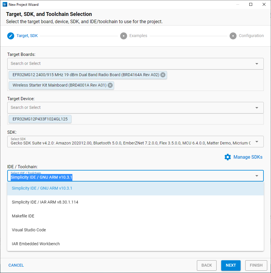
Open SSv5’s File menu and select New > Silicon Labs Project Wizard. The Target, SDK, and Toolchain Selection dialog opens. If you want to change the toolchain from the default GCC to IAR, do so here. Click NEXT.
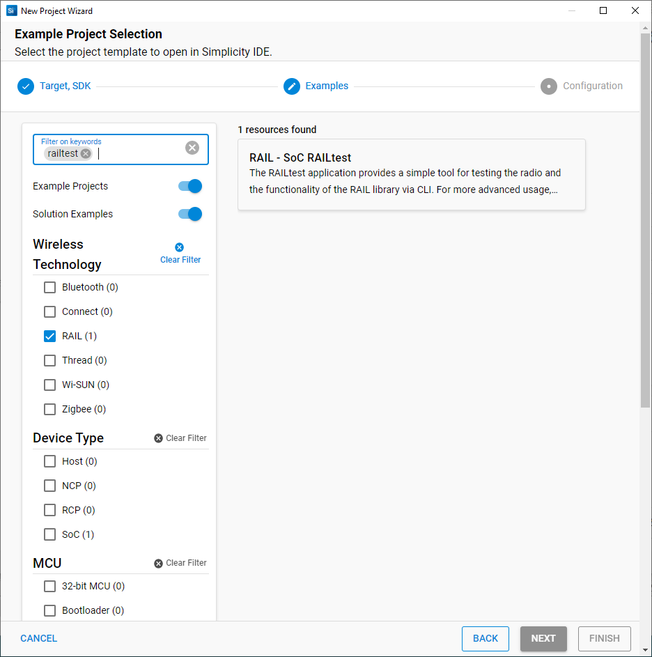
The Example Project Selection dialog opens. A variety of filters are available to help you find a specific example, such as ‘railt’ and Technology Type: Proprietary in the following figure. Select the example, in this case RAIL – SoC RAILtest. Select it and click NEXT.
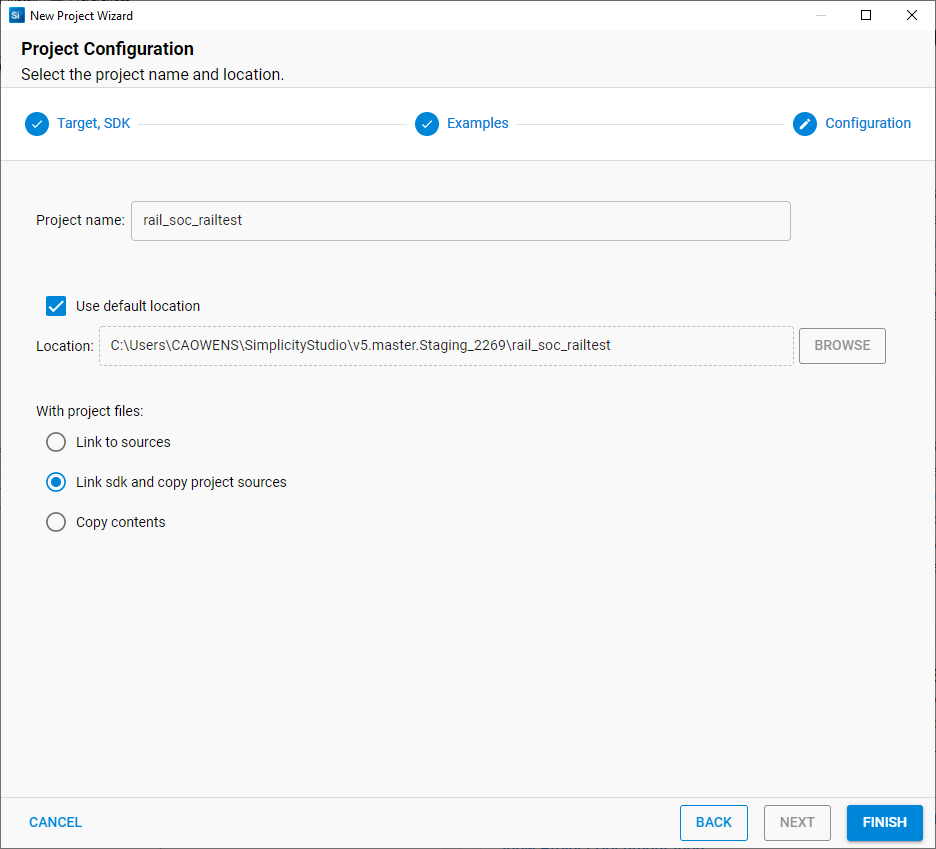
The Project Configuration dialog opens. Here you can rename your project, change the default project file location, and determine if you will link to or copy project files. Note that if you change any linked resource, it is changed for any other project that references it. Click FINISH and project generation will start.
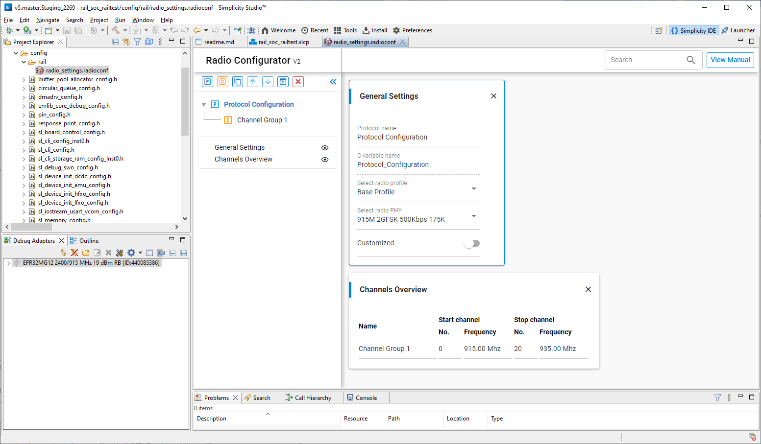
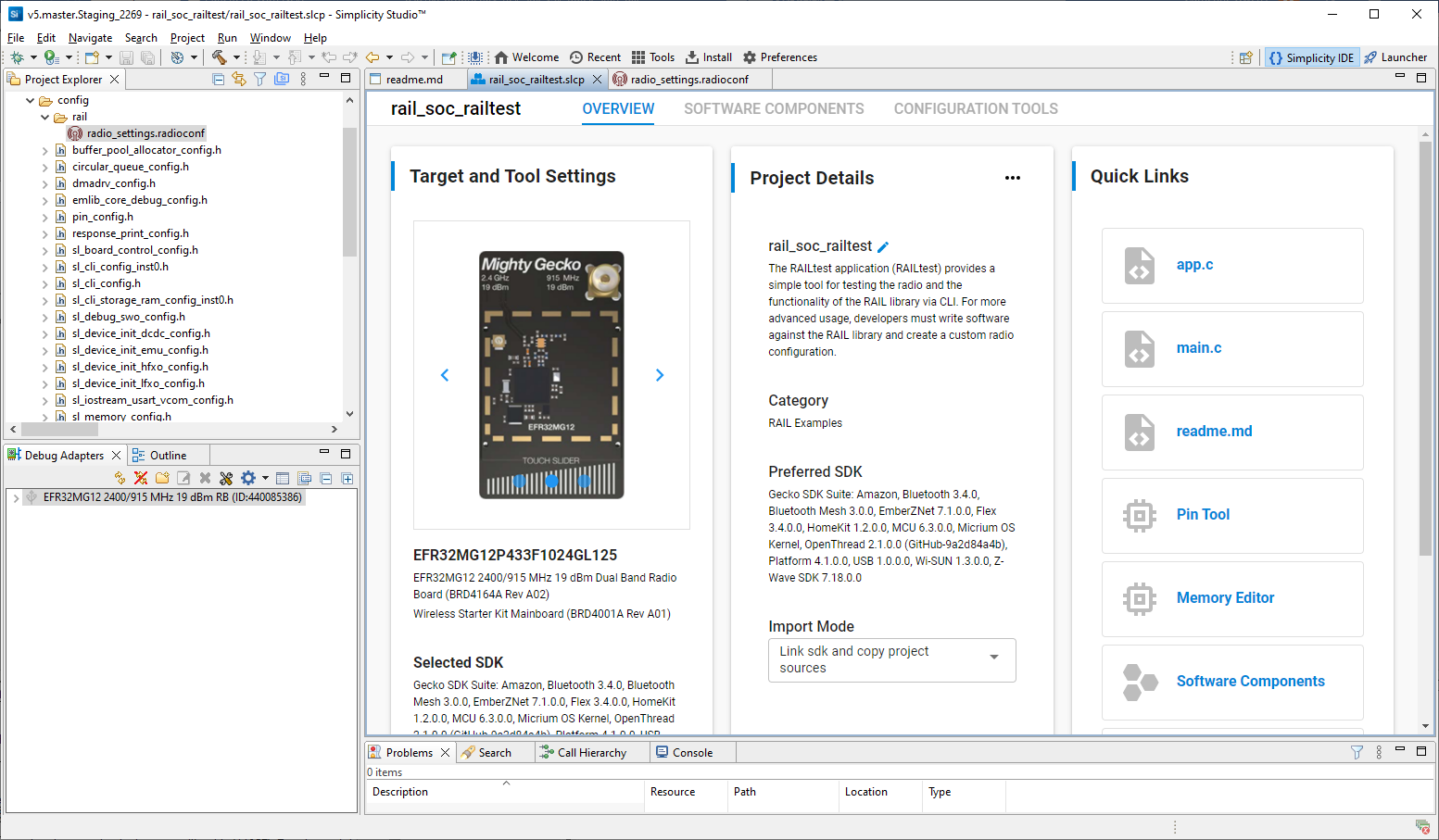
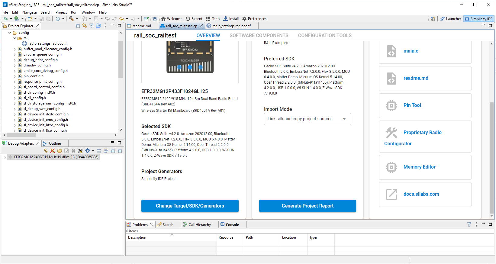
The new project opens in the Simplicity IDE Perspective with the Radio Configurator tab (radio_settings.radioconf) selected. The Project Configurator tab (<projectname>.slcp) and a description of the project (readme.md) are also available.
Component Configuration#
Click the <projectname>.slcp tab to open the Project Configurator. The default configuration settings will work on the connected development board so, when first experimenting with a development kit, keeping them unchanged and going straight to compiling and flashing is recommended.
Flex SDK v3.x projects incorporate a Gecko Platform component-based architecture. Software features and functions can be installed and configured through the Component Library. The installation process will:
Copy the corresponding SDK files from the SDK folder into the project folder.
Copy all the dependencies of the given component into the project folder.
Add new include directories to the project settings.
Copy the configurations files into the /config folder.
Modify the corresponding auto-generated files to integrate the component into the application.
Additionally, “init” type software components will implement the initialization code for a given component, utilizing their corresponding configuration file as input.
Some software components (like Parent support) will fully integrate into the application to perform a specific task without the need of any additional code, while other components provide an API to be used in the application.
To see the component library, go to the SOFTWARE COMPONENTS tab.
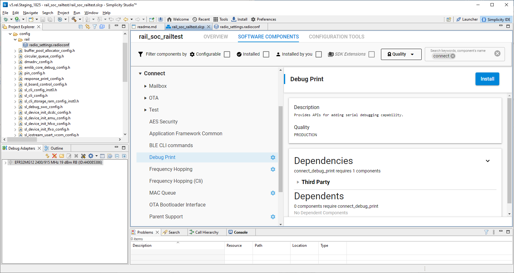
The project is configured by installing and uninstalling components, and configuring installed components. Installed components are checked. Configurable components have a gear symbol. Select a component to see information about it. A number of filters as well as a keyword search are available to help you explore the various component categories. Note that components for all installed SDKs are presented. See the online Simplicity Studio 5 User’s Guide for details about the functionality available through the Simplicity IDE perspective and the Project Configurator.
If the component is configurable, click CONFIGURE to open the Component Editor.
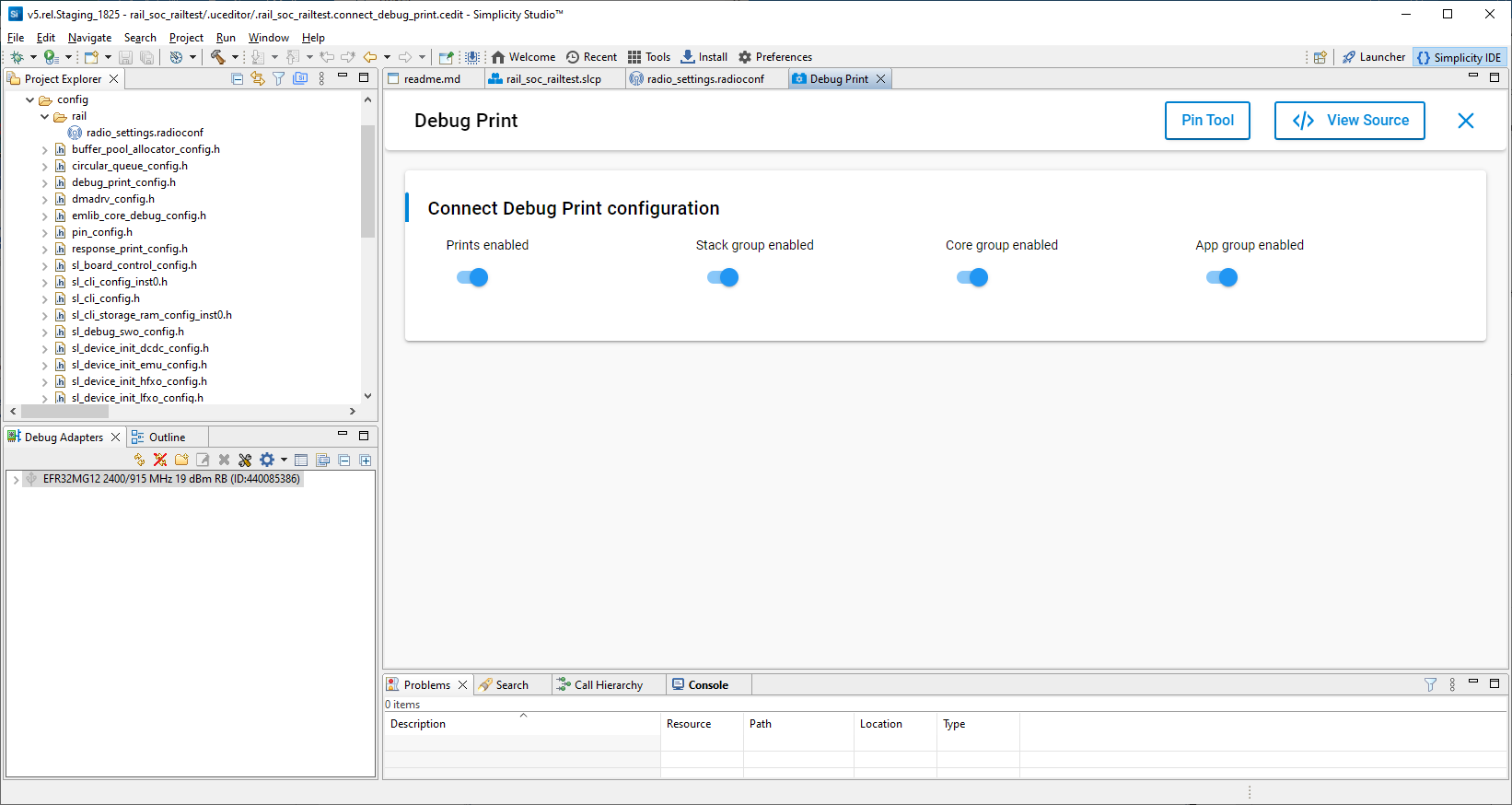
Any changes you make in the Component Editor are autosaved.

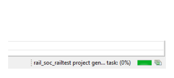
As you install and otherwise make changes in the Project Configurator, project files are autogenerated. Progress is shown in the lower right corner of the Simplicity IDE perspective.
Radio Configuration#
If the radio_settings.radioconf tab is not present, click the Project Configurator CONFIGURATION TOOLS tab. Click Open next to the Radio Configurator. It will open the radio_settings.radioconf file of the /config/rail folder in the Radio Configurator.
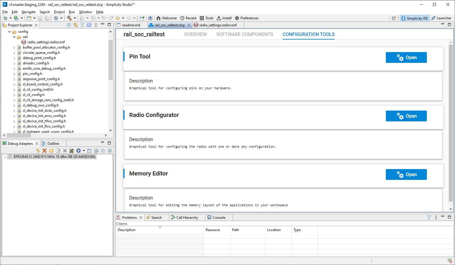
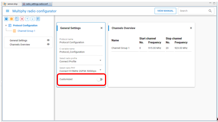
Select a radio profile, and a pre-defined radio PHY of the selected profile. You can then customize the PHY by turning on Customized. Changes made in the Radio Configurator are not autosaved. When saving the changes to radio_settings.radioconf, the radio configuration will be autogenerated and saved in the /autogen/rail_config.h and /autogen/rail_config.c files. See Proprietary Radio Configurator Guide for more information on using the Radio Configurator.
Pin Tool#
On the CONFIGURATION TOOLS tab, click Open next to Pin Tool. This will open the file <project>.pintool of the project in the Pin Tool, which allows you to easily configure new peripherals or change the properties of existing ones. You can also double-click the file <project>.pintool in the Project Explorer view to open it.
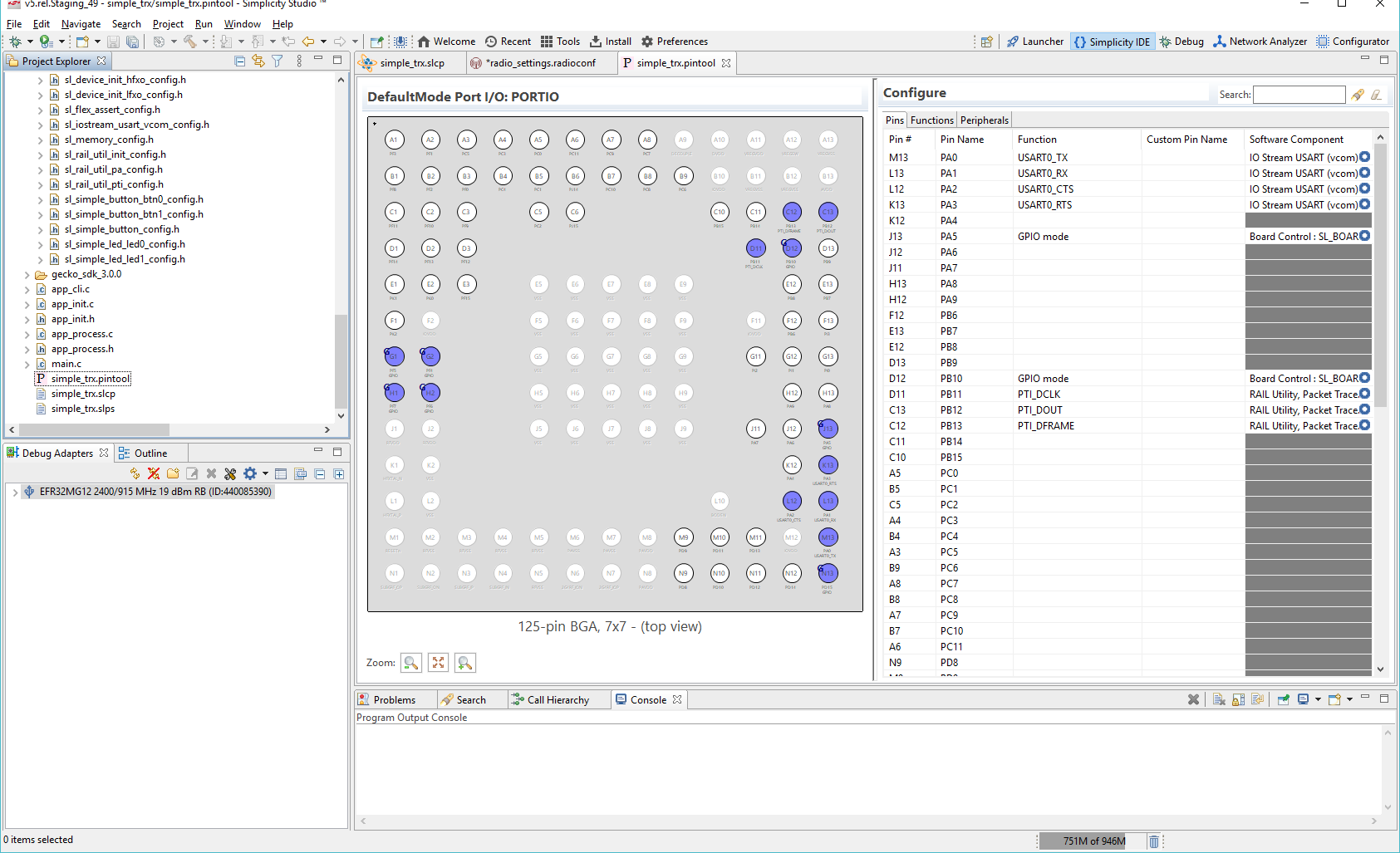
Double-click a Software Component to open the Component Editor and configure that function. Pin Tool does not autosave.
Compiling and Flashing the Application#
You can either compile and flash the application automatically, or manually compile it and then flash it.
Automatically Compile and Flash#
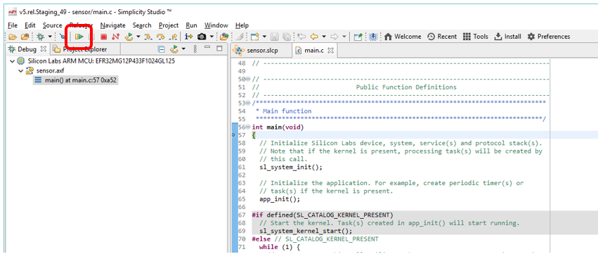
You can automatically compile and flash the application to your connected development hardware in the Simplicity IDE. Click the Debug control.

Progress is displayed in the console and a progress bar in the lower right.
When building and flashing are complete, a Debug perspective is displayed. Click the Resume control to start the application running on the device.
Next to the Resume control are Suspend, Disconnect, Reconnect, and stepping controls. Click Disconnect when you are ready to exit Debug mode.

Manually Compile and Flash#
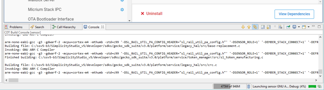
After you generate the project files, instead of clicking Debug in the Simplicity IDE, click the Build control (hammer icon) in the top tool bar.
The sample application will compile based on its build configuration. You can change the build configuration at any time by right-clicking the project directory in Project Explorer view and opening Build Configurations > Set Active.
You can also build your application directly in IAR-EWARM by opening IAR-EWARM and opening the generated project file inside IAR. To generate the file for IAR EWARM, go to the OVERVIEW tab of the Project Configurator, scroll down, and click Change Target/SDK/Generators on the Target and Tool Settings card, drop down the list under CHANGE PROJECT GENERATORES, and include IAR EMBEDDED WORKBENCH PROJECT. The .eww file is created after you save the change.
Open IAR-EWARM.
Select File > Open > Workspace and navigate to the location you selected for your sample application.
Select the application .eww file and click Open.
Select Project > Make or press F7. If the application builds without errors, you are ready to install the image on a device.
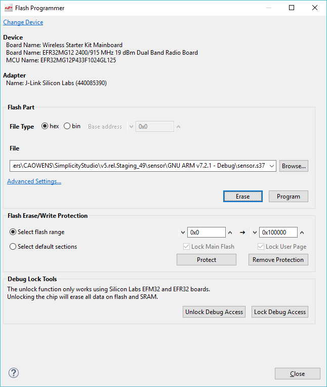
You can load the binary image through Project Explorer view. Locate the <project>.bin, .hex, or .s37 file in the Binaries subdirectory.
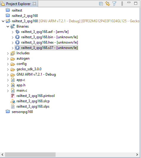
Right-click the file and select Flash Programmer. The Flash Programmer opens with the file path populated. Click Program.
Interacting with Examples#
Depending on the example application, you may be able to interact with it through buttons, LEDs and the LCD of the mainboard and through your development environment’s Console interface using a CLI (command line interpreter).
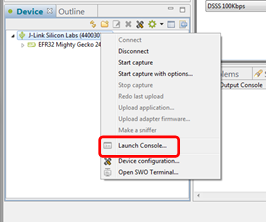
To launch the Console interface, in the Simplicity IDE perspective right-click on the debug adapter in the Debug Adapters view. Choose Launch Console. Alternatively, from the Tools icon in the Simplicity IDE toolbar, or on the COMPATIBLE TOOLS tab in the Launcher perspective, select Device Console. Select the Serial 1 tab and click Enter to get a prompt from the sample app CLI.
In the RAILtest application the console interface allows testing of any RAIL feature. Enter “help” to get a list of the available CLI commands.
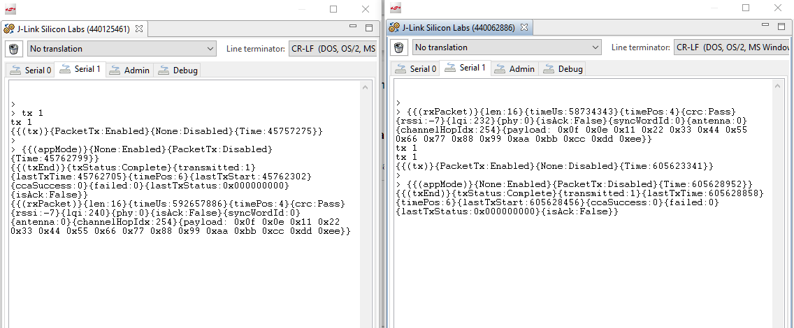
For a simple radio functionality test flash the same RAILtest binary on two radio boards and open a console for each of them. Make sure an antenna is connected to each radio board if applicable. RAILtest starts in RX state on both boards.
Type tx 1 in the first console window. The first radio node will transmit one packet and then return to RX state. A received packet will be reported in the second console window by the second radio node.
Type tx 1 in the second console window. The second radio node will transmit one packet and then return to RX state. A received packet will be reported in the first console window by the first radio node.
The following figure shows the consoles at the end of the procedure.
Working with Custom Boards#
When working with custom boards, two methods are available, depending on your needs:
Create an example on the mainboard, then remove the mainboard on the Project Configurator OVERVIEW tab using the Change Target/SDK control. This way, the wiring of the kit is kept, but you can change it using the Pin Tool.
Create an example with just the part, no mainboard, and set up the wiring for all required peripherals of the example (like buttons or pins) using the Pin Tool.
Note that a mainboard can also depend on components (typically peripheral init components) that are removed if you remove the mainboard from the project.