Using the Long Range Profile in Simplicity Studio 5#
Long Range Profile in the Radio Configurator#
Simplicity Studio 5 (SSv5) makes it easy to access Long Range PHY configurations by selecting the new "Long Range" profile in the Radio Configurator interface. If you need a refresher, see the Simplicity Studio 5 User’s Guide and Proprietary Radio Configurator Guide for more information on building an example wireless application with the Radio Configurator.
Click the Select radio profile drop-down field, and select Long Range Profile. Note that PHYs in this profile have reduced configuration options (carrier frequency, and FEC enable), described here:
Carrier frequency can be set to anywhere within each band – baseband performance will be sustained at all frequencies within a given band. However, be aware that external components can exhibit a frequency dependence.
425MHz to 525MHz, or 860MHz to 930 MHz
FEC (Forward Error Correction) can be enabled for any of the PHY configurations:
FEC in EFR32 Series 1 simply doubles the number of transmitted symbols. Enabling FEC does not automatically adjust the data rate. To maintain the original effective throughput, manually select a data rate that is twice the original rate.
FEC does not increase sensitivity, but it can protect against missing bits due to interferer signals.
Silicon Labs Connect does not currently support FEC, so if you plan to use these PHYs with Connect, do not enable FEC.
The next section provides a procedure to construct a complete example application with which to evaluate PHYs in the Long Range Profile using two EFR32 radio boards.
Build a Range Test Example Application#
This section describes the steps to build a Range Test application, and is based on UG147: Range Test Demo User's Guide. Additional guidance on using the Range Test application can be found in this article. The procedure assumes that you have downloaded the Flex SDK, and have connected the two boards required for this example, as described in the Simplicity Studio 5 User’s Guide.
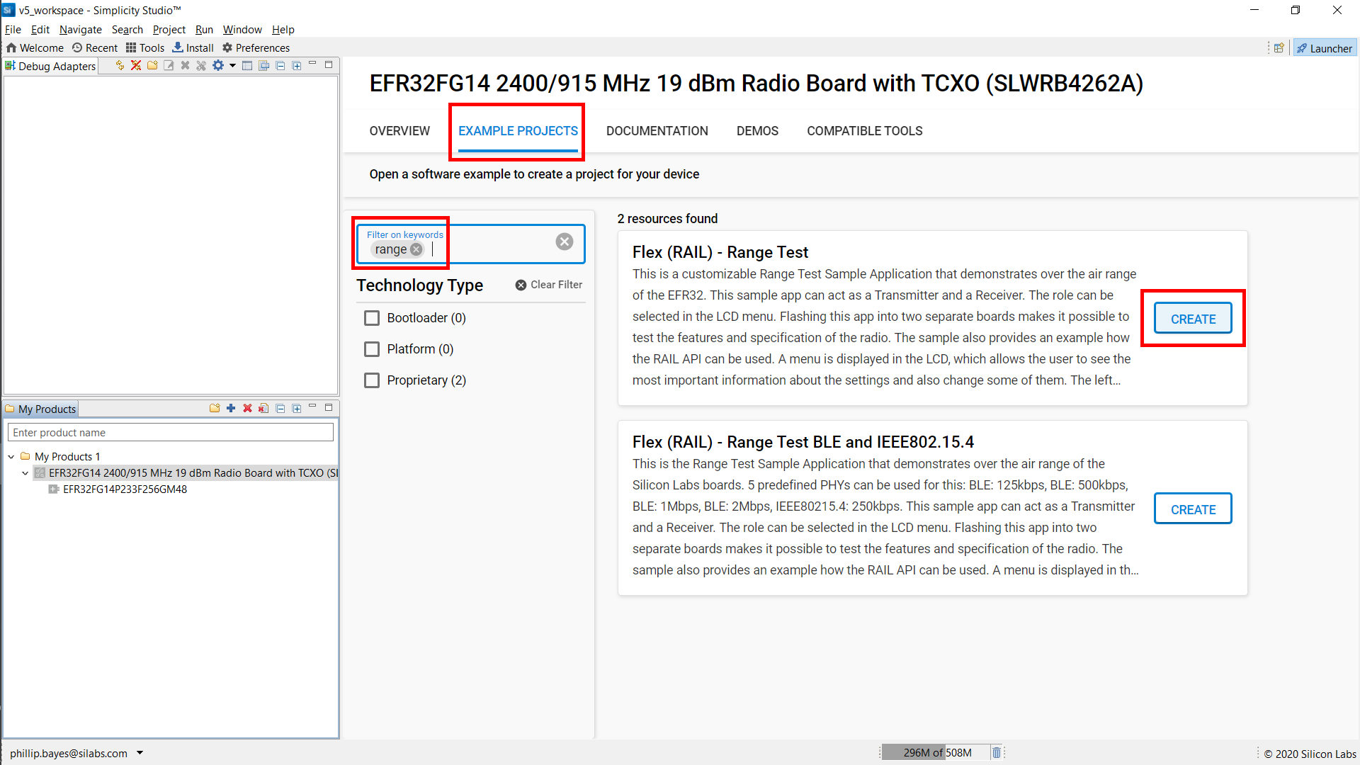
Click the “Example Projects” tab to see the projects available for the selected target hardware.
Scroll down or use the example filter to locate the “Flex (RAIL) – Range Test” project, then click CREATE.
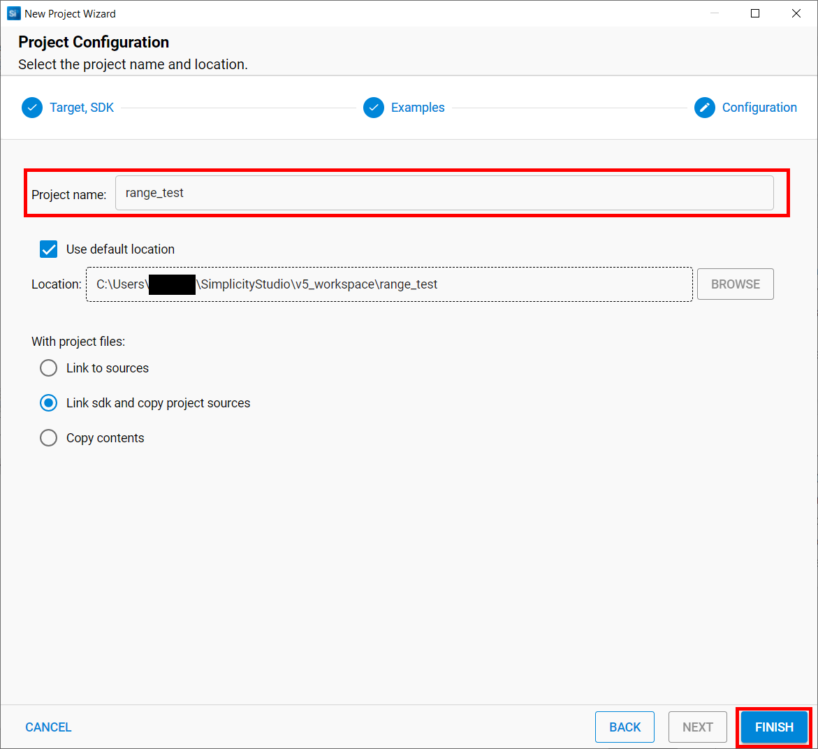
Enter the name of the project you want to create, or just leave it as the default, “range_test”..
Click FINISH to create the new project.
Once the project is created, SSv5 opens the Simplicity IDE perspective, and the radio configuration GUI appears. From the Project Explorer view you can see the project files that have been generated.
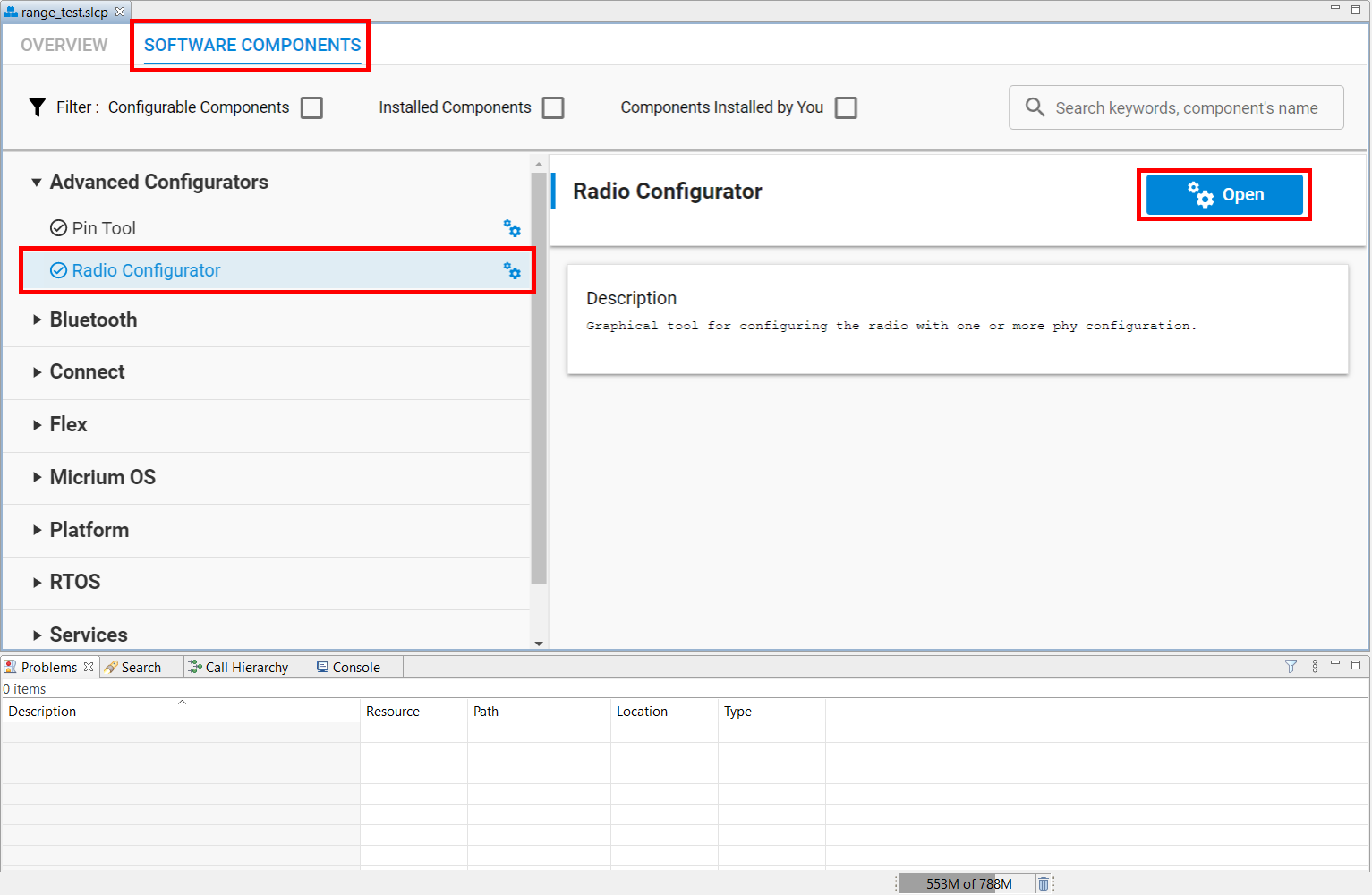
If you close this tab, the Radio Configurator can be accessed again at any time via the Software Components tab. Click the Advanced Configurators item, then Radio Configurator (alternatively, you can simply search for configurator using the search input at the top right of the .slcp frame). Once this Radio Configurator gateway element has been located, simply click OPEN to its right and proceed to the next step.
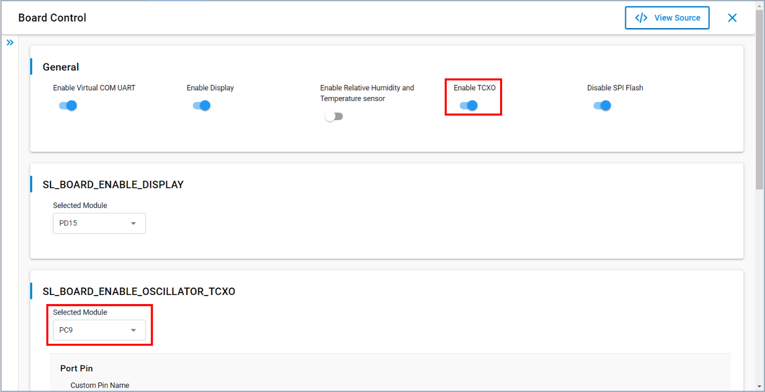
If you have a radio board with a TCXO on it, SSv5 automatically preconfigures your project to support it and adds the code segments enabling the TCXO to the application. For reference, the configuration can be manually overridden via the Board Control component.
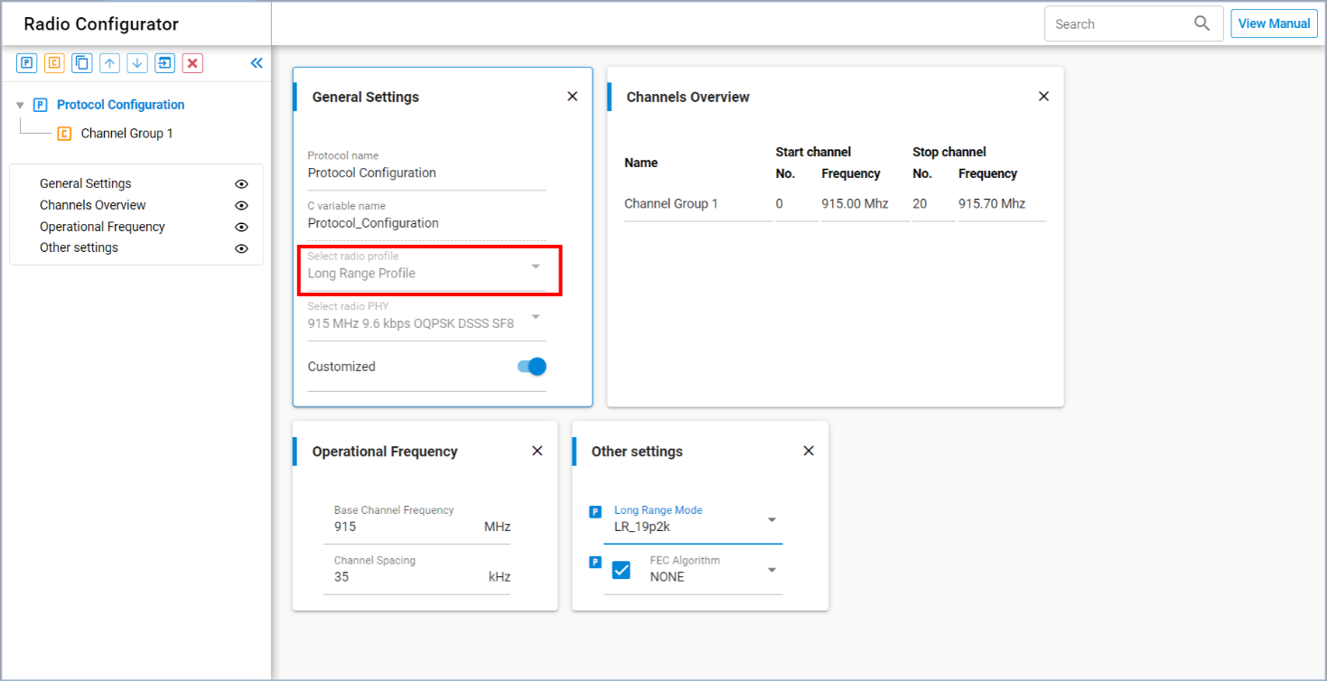
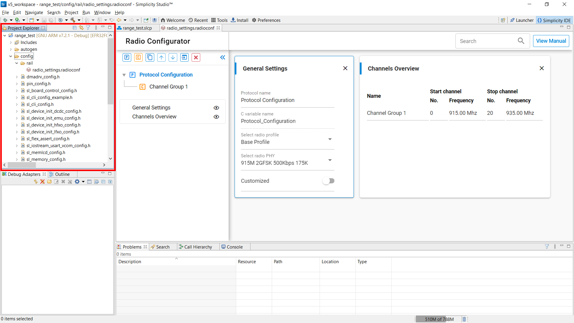
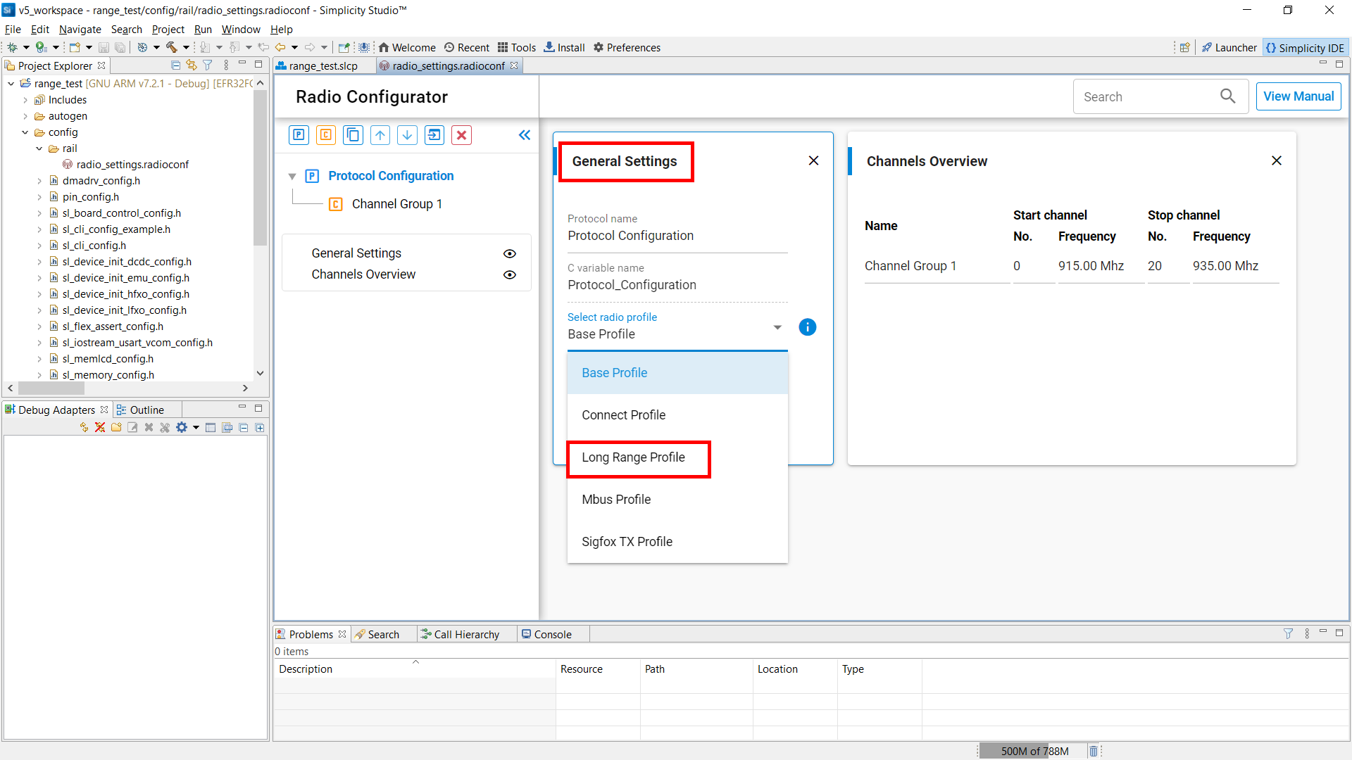
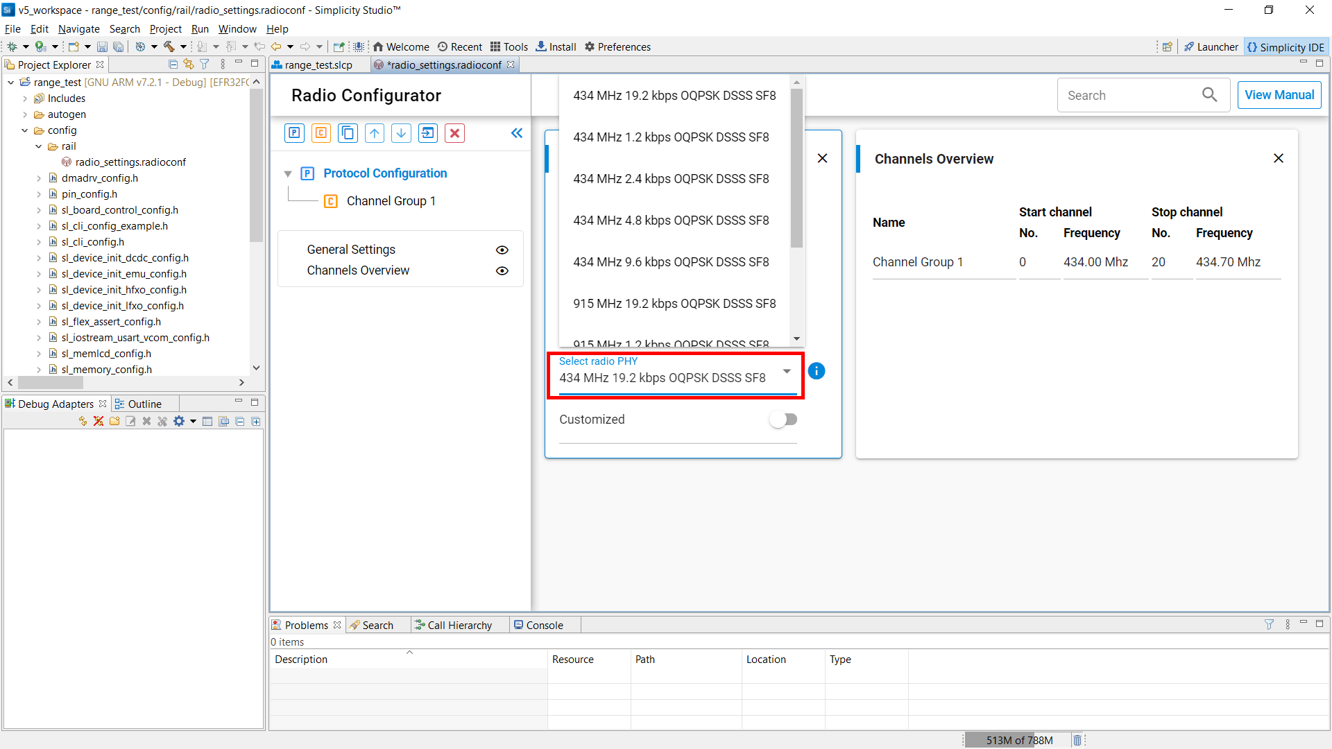
Before configuring a Long Range PHY, you must adjust the selected radio profile for the project. On the Navigation Panel, click Protocol Configuration. You should see the General Settings and Channel Overview cards open in the editor window on the right.
On the General Settings card, click the Select radio profile drop-down field, and select Long Range Profile.
On the Select radio PHY field, choose one of the predefined long range configurations, keeping the following guidance in mind:
For 434-490 MHz boards, select a 434 MHz config.
For 868-915 MHz boards, select a 915 MHz config.
Note that Silicon Labs typical radio boards have a +/- 10ppm crystal as a reference. Refer to the "PHY Configuration Options on the Long Range Profile" table in Development of the EFR32 Long Range PHYs to verify support for your preferred PHY using two (2) +/- 10ppm radio boards (+/- 20ppm combined). If your PHY of choice requires tighter tolerance, use the TCXO-equipped radio boards listed in the "Radio Boards with TCXO" table in Radio Boards Supporting Long Range PHY Evaluation.
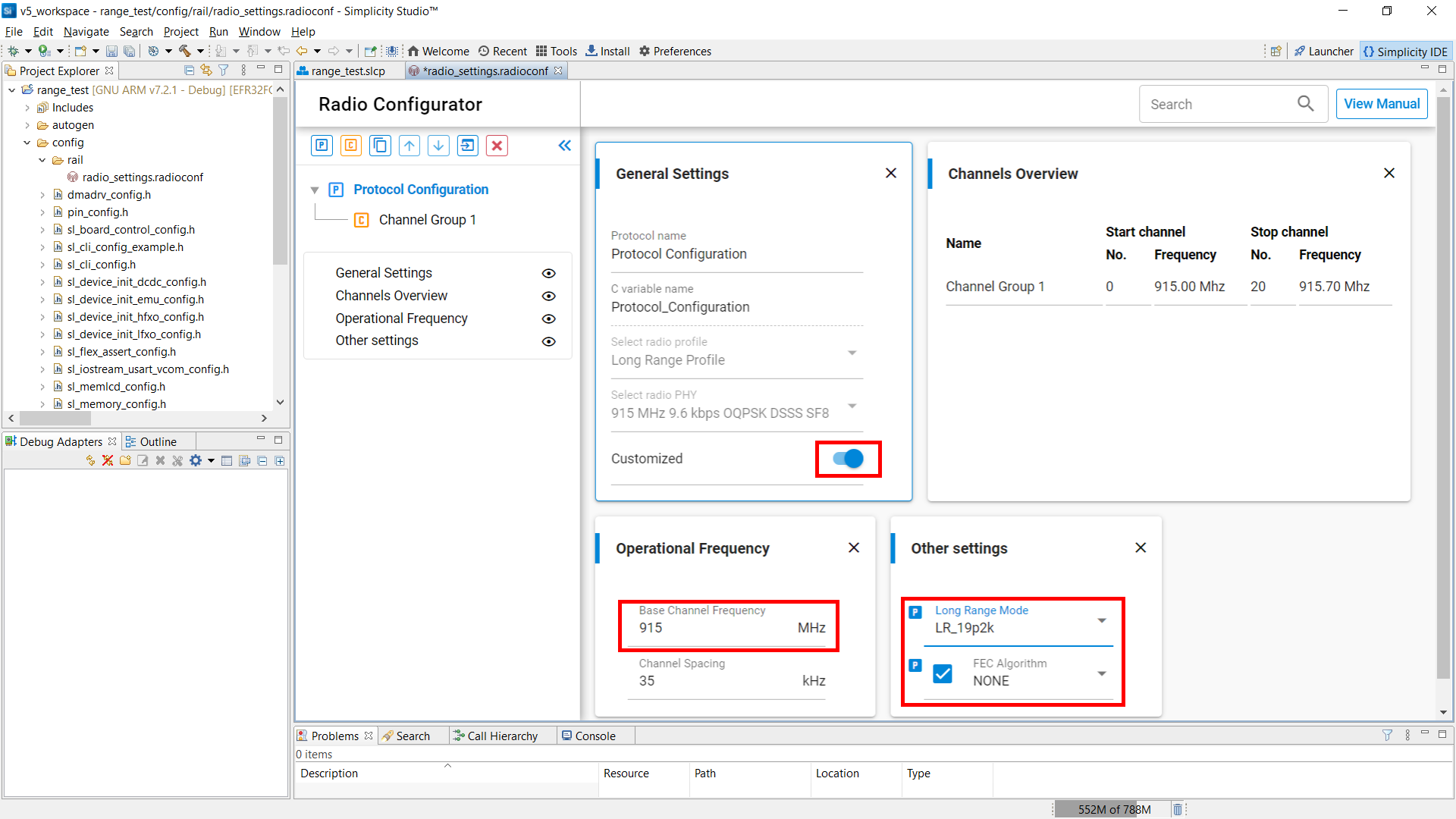
Enable the Customized switch, to allow fine tuning of the selected PHY config.
On the Operational Frequency card, set the Base Channel Frequency according to your planned operating band.
On the Other settings card, you have the option to override the data rate selection and/or to enable FEC.
(Note: On an EFR32, enabling FEC doubles the number of transmitted symbols, but does not automatically adjust the data rate. To retain the original (before enabling FEC) effective throughput with FEC, you must manually select a doubled data rate.)
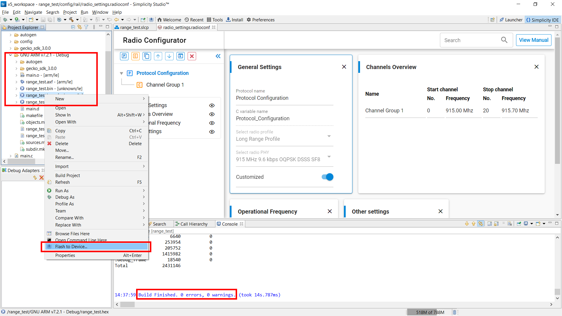
Build the project by clicking the hammer toolbar button.
Once built, flash the generated hex file to the target by right-clicking the <project name>.hex file in the “GNU ARM v7.2.1 – Debug” folder, and selecting Flash to Device…
The Flash Programmer will open. Click Program to download the code to the target.
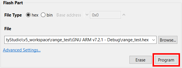
Now flash the same .hex file to your second radio board. Select the other WSTK mainboard as the target device, and click Program.