Bypass Mode#
Bypass Mode in UART/USB-CDC#
Making Default Wireless Firmware Selection#
With this option, the host can select the default firmware image to be loaded.
Selecting a Valid Image as the Default Image#
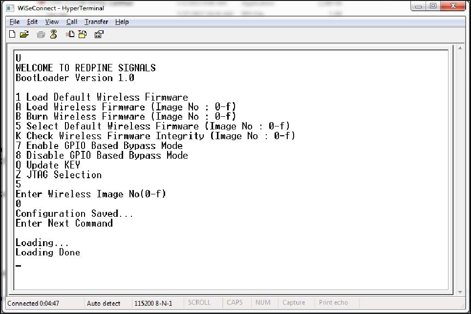
After the welcome message is displayed, host can select Option 5 "Select Default Wireless Firmware (Image No: 0-f)".
The message "Enter Wireless Image No (0-f)" is displayed on the screen
Select image number.
It is better to check the integrity of image before selecting it as default image.
When default image is selected, module checks for the validity of the image selected and displays "Configuration saved".
Enable/Disable GPIO Based Bypass Option#
This option is for enabling or disabling the GPIO bootloader bypass mode.
Enabling the GPIO Based Bypass Mode#
If you select option 7, GPIO based bypass gets enabled.
When this option is selected, module checks for the validity of the image selected and displays "Configuration saved" if valid.
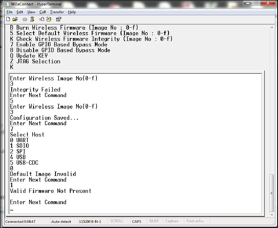
If valid default image is not present, then a message saying "Default image invalid" will be displayed.
Once enabled, from next bootup, the Bootloader will latch the value of LP_WAKEUP. If asserted, it will bypass the whole boot loading process and will load the default firmware image selected.
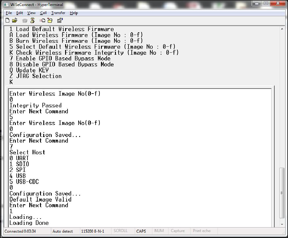
After the welcome message is displayed, select option 5 "Select Default Wireless Firmware (Image No: 0-f)".
The window will display "Enter Wireless Image No. (0-f)".
Select the required image no.
It is better to check the integrity of image before selecting it as default Image.
When default image is selected, the module checks for the validity of the image selected and displays "Configuration saved".
After this, select option 7 "Enable GPIO Based Bypass Mode".
The module responds to select the host interface in Bypass mode (0 - UART, 1 - SDIO, 2 - SPI, 4 - USB, 5 - USB-CDC).
Select the required interface.
If the default image is valid, then it enables GPIO Bypass mode, otherwise it will not enable the GPIO Bypass mode.
Disabling the GPIO Based Bypass Mode#
If host selects option 8, GPIO based bypass gets disabled.
NOTE:
GPIO-15 needs to be de-asserted on power up to move to host interaction mode, to select bootup options like disable Bypass mode or to change default image.
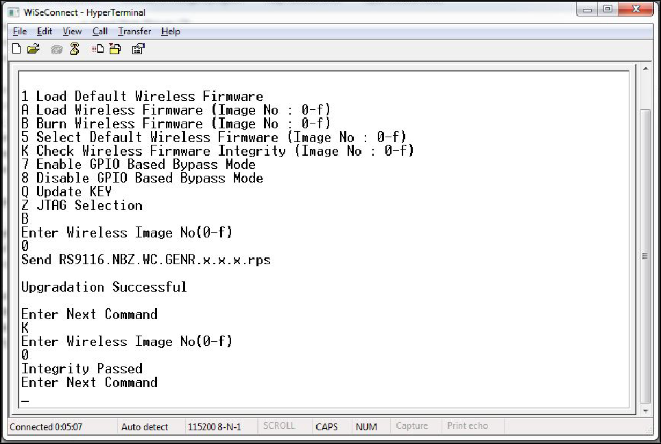
Check Integrity of the Selected Image#
This option enables user to check whether the given image is valid or not. When this command is given, bootloader asks for the image for which integrity has to be verified as shown in figure below:
Other Operations#
This section contains additional, less frequently used bootloader options.
Update KEY
NOTE:
This feature is not enabled in the current release.
JTAG Selection
NOTE:
This feature is not enabled in the current release.