Host Interaction Mode#
In this mode, host interaction varies based on the host interface. Host interaction in SPI/USB and UART/USB-CDC are different. In UART/USB-CDC, boot-up options are menu-based while SPI/USB uses command exchanges. The details are explained below for UART and USB-CDC.
Host Interaction Mode in UART/USB-CDC#
This section explains the host interaction mode in UART/USB CDC mode.
Startup Operation#
After powering up, the host is required to carry out an Auto Baud Rate Detection (ABRD) operation. After a successful ABRD, the module displays the menu of boot-up options to the host. The host then needs to select the appropriate option.
NOTE:
On power up, the bootloader checks the integrity of the bootup options. If the integrity fails, the bootloader computes the integrity from backup. If integrity passes, the bootloader copies the backup to the actual location. If the integrity of the backup options also fails, the bootup options are reset/cleared. In either of the cases, bootloader bypass is disabled or corresponding error messages are given to the host. In case of integrity failure and when the backup integrity check passes, the "LAST CONFIGURATION NOT SAVED" message is displayed. When backup integrity also fails, “BOOTUP OPTIONS CHECKSUM FAILED" is displayed before displaying the bootup options.
Hyper Terminal Configuration#
RS9116W uses the following UART interface configuration for communication:
Baud Rate: The following baud rates are supported by the module: 9600 bps, 19200 bps, 38400 bps, 57600 bps, 115200 bps, 230400 bps, 460800 bps, and 921600 bps.
Data Bits: 8 Parity: None Stop Bits: 1
Flow Control: None
Before powering up the module, follow the sequence of steps as given below:
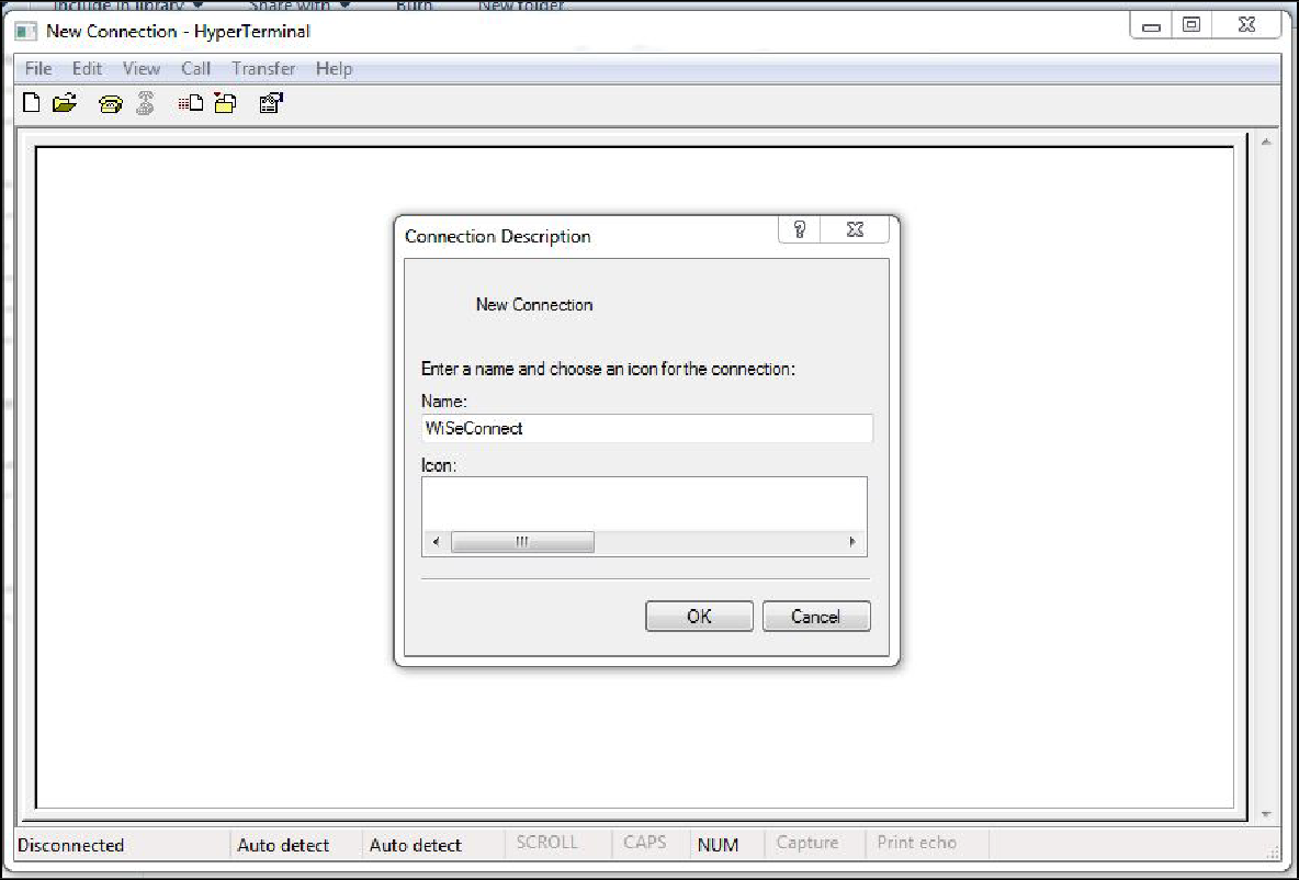
Open HyperTerminal and enter any name in the "Name" field. After this, click the "OK" button. Here, "WiSeconnect" is entered as shown below:
NOTE:
The default baud rate of the module is 115200 bps.
After clicking "OK", the following dialog box is displayed as shown in the figure below:
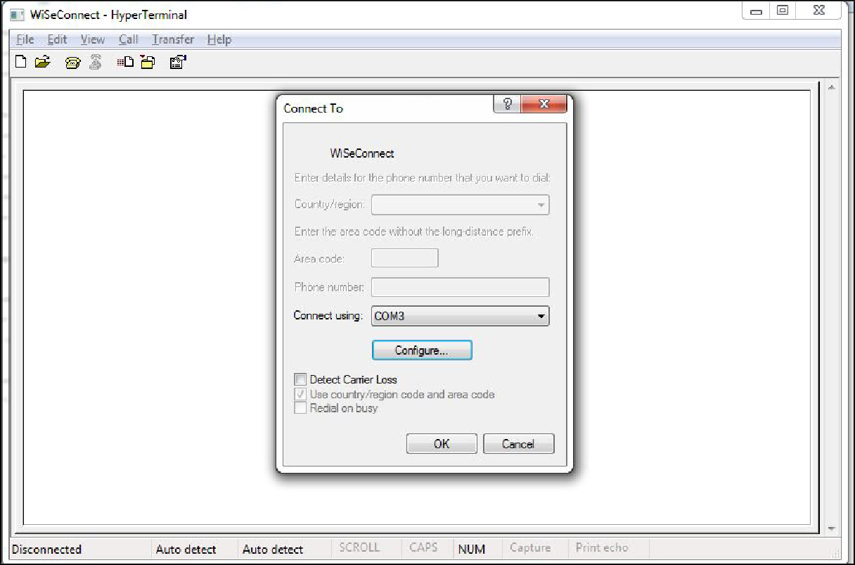
In the Connect using" field, select the appropriate com port. In the figure above COM3 is selected. Click the "OK" button.
After clicking the "OK" button, the following dialog box is displayed as shown in the figure below:
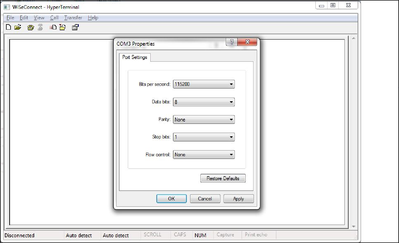
Set the following values for different fields in the above figures as given below:
Set baud rate to 115200 in "Bits per second" field.
Set Data bits to 8 in "Data bits" field.
Set Parity to none in "Parity" field.
Set stop bits to 1 in "Stop bits" field.
Set flow control to none in "Flow control" field.
Click "OK" button after entering the data in all the fields.
Auto Baud Rate Detection (ABRD)#
The RS9116 automatically detects the baud rate of the Host's UART interface by exchanging some bytes. The Host should configure the UART interface for the following parameters for ABRD detection.
RS9116 uses the following UART interface configuration for communication:
Baud Rate: The following baud rates are supported: 9600 bps, 19200 bps, 38400 bps, 57600 bps, 115200 bps, 230400 bps, 460800 bps, and 921600 bps.
Data Bits: 8
Stop Bits: 1
Parity: None
Flow Control: None
To perform ABRD on the RS9116W, the host must follow the procedure outlined below:
Configure the UART interface of the host at the desired baud rate.
Power on the board.
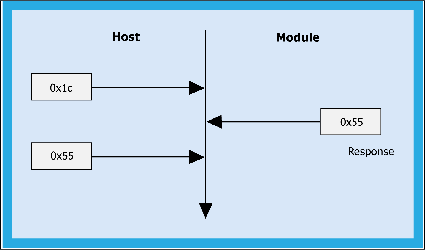
After releasing the module from reset, the host should wait for 20 ms for the initial boot-up of the module to complete and then transmit 0x1C at the baud rate with which its UART interface is configured. After transmitting '0x1C' to the module, the Host should wait for the module to transmit 0x55 at the same baud rate.
If the '0x55' response is not received from the module, the host has to re-transmit 0x1C, after a delay of 200ms.
After finally receiving '0x55', the host should transmit '0x55' to the module. The module is now configured with the intended baud rate.
NOTE:
Performing ABRD in host interaction mode is a must for USB CDC mode.
Below are the boot-up options, firmware upgrade, and firmware loading procedures for the product.
Startup Messages on Power-up#
After powering up the module and performing ABRD you will see a welcome message on the host, followed by the boot up options.
NOTE:
Windows HyperTerminal is used to demonstrate boot up/upgrade procedure.
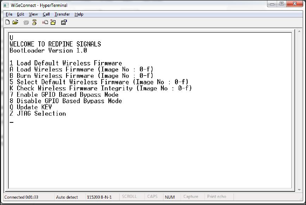
Loading the Default Wireless Firmware in the Module#
To load the default firmware flashed onto the module, choose Option 1: "Load Default Wireless Firmware ".
After the welcome message is displayed as shown in the above figure, select Option 1 "Load Default Wireless Firmware " for loading the image.
NOTE:
By default, the module will be configured in AT mode. If a mode switch from AT plus command mode to binary mode is required, the user must provide 'H' in the bootloader options.
The module lasts in the binary mode unless it changed to AT plus command mode and vice-versa. To change from binary mode to AT mode, then user must provide 'U' in the bootloader options.
To load the selected firmware (from flash) onto the module, choose Option A: "Load Wireless Firmware (Image No: 0-f)".
Load Wireless Firmware#
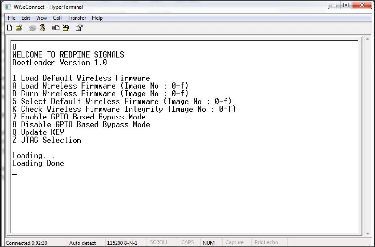
After the welcome message is displayed as shown in the above figure, select option A "Load Wireless Firmware (Image No: 0-f)" to load the image.
In response to option A, the Module asks to enter the image no.
Select the image no. to be loaded from flash.
After successfully loading the default firmware, the "Loading Done" message is displayed.
After firmware loading is completed, the module is ready to accept commands.
NOTE:
In order to use host bypass mode, the user has to select one of the images as the default image by selecting option 5 (Select Default Wireless Firmware).
In Host interaction mode, if there is no option selected after the bootup menu for 20 seconds, then the bootloader will load selected Wireless default image.
If a valid firmware is not present, then a message prompting "Valid firmware not present" will be displayed.
Firmware Upgradation#
After powering up the module, a welcome message is displayed.
Upgrade NWP Firmware Image#
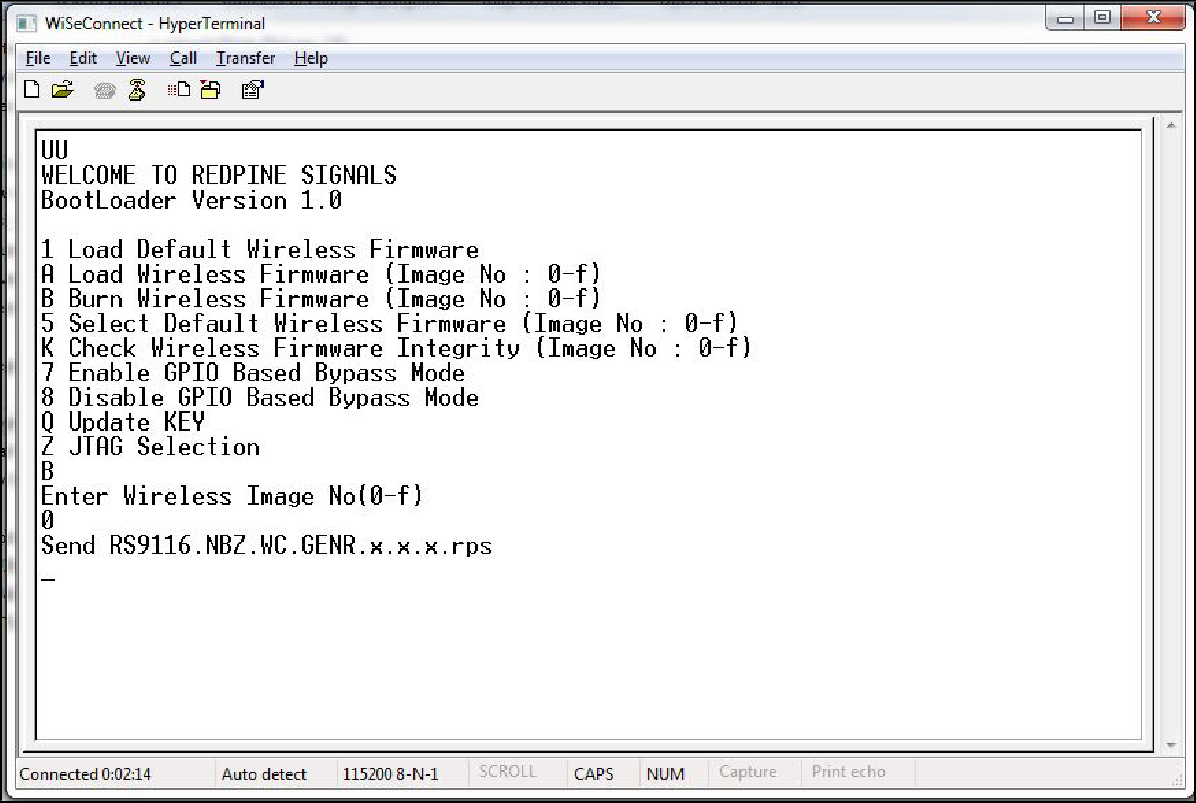
After the welcome message is displayed, select option B "Burn Wireless Firmware (Image No: 0-f )" to upgrade Wireless Image.
The message "Enter Wireless Image No (0-f)"
Then select the Image no to be upgraded.
The message "Send RSXXXXX.NBZ.WC.GENR.x.x.x.rps" should appear as shown in the figure below:
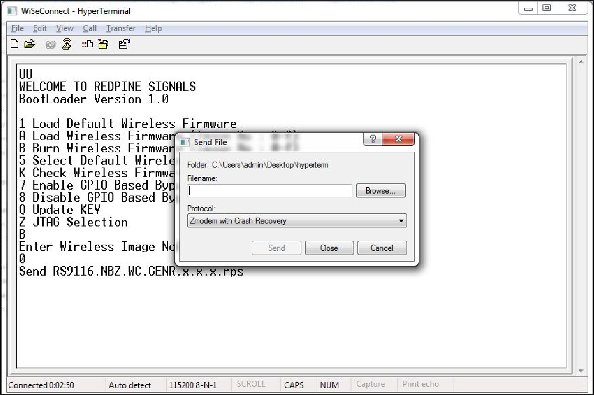
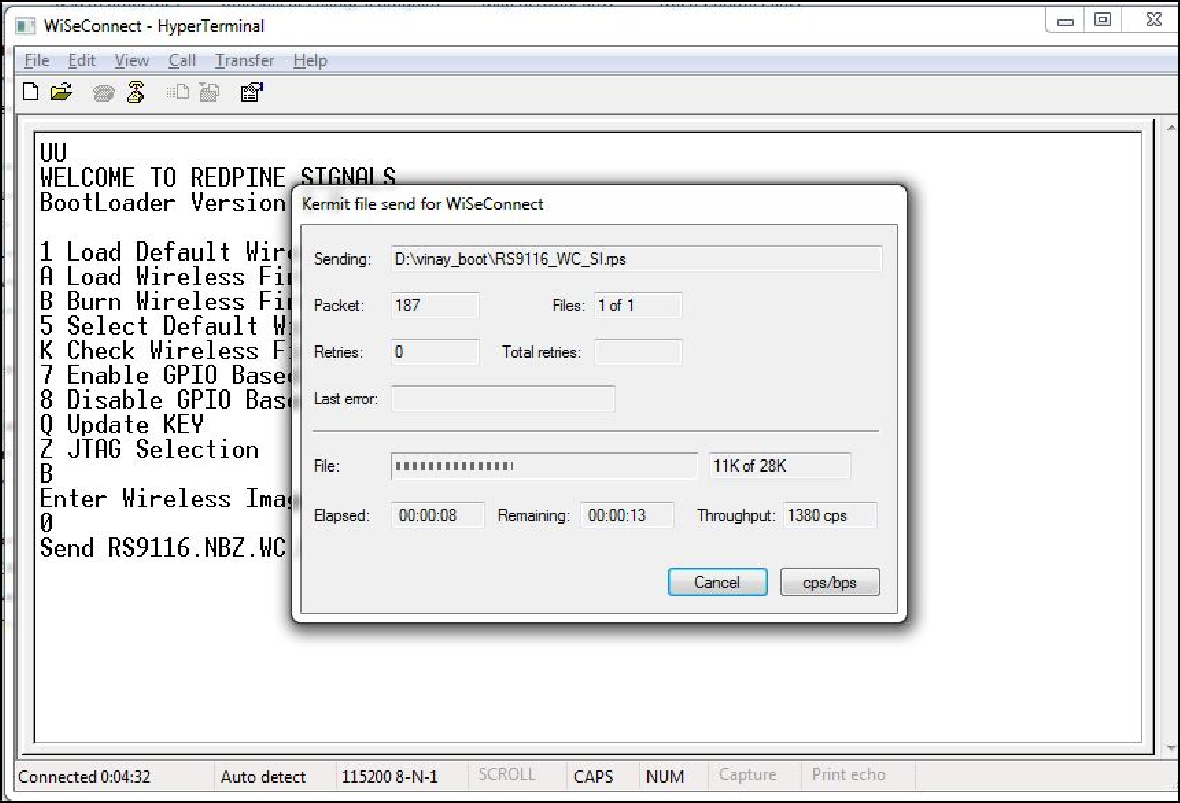
In the "File" menu of HyperTerminal, select the "send file" option. A dialog box will appear as shown in the figure below. Browse to the path where "RS9116.NBZ.WC.GENR.X.X.X.rps" is located and select Kermit as the protocol option. After this, click the "Send" button to transfer the file.
The dialog box message is displayed while file transfer is in progress as shown in the figure below:
After successfully completing the file transfer, module computes the integrity of the image and displays "Upgradation Failed, re-burn the image" in the case of failure. Module displays "Upgradation Failed and default image invalid, Bypass disabled" in the case of both failure and corruption of the default image.
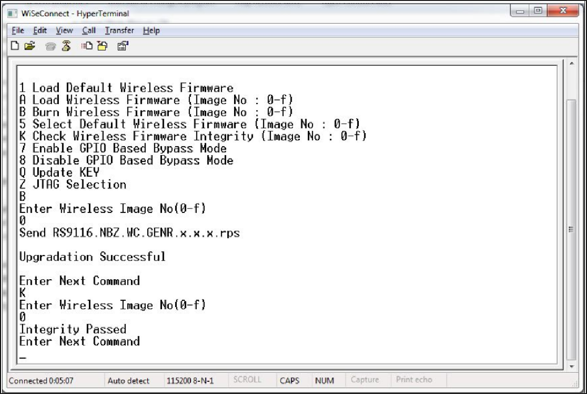
In the case of success, module checks if bootloader bypass is enabled and computes the integrity of the default image selected. If the integrity fails, it sends "Upgradation successful, Default image invalid, gpio bypass disabled". If integrity passes or gpio bypass is not enabled, it sends an "Upgradation Successful" message on terminal as shown in the figure below:
At this point, the upgraded firmware image is successfully flashed to the module.
The user can again cross-check the integrity of the Image by selecting Option K " Check Wireless Firmware Integrity (Image No: 0-f)" for Wireless Image.
Follow the steps mentioned in the section Loading the Default Wireless Firmware in the Module to load the firmware from flash, select Option 1 from the above shown figure.
The module is ready to accept commands from the host.