


Getting Started with Silicon Labs Bluetooth Channel Sounding#
Overview#
This guide takes you from unboxing a Silicon Labs Channel Sounding (CS) kit to a working distance measurement, then through guided experiments that show how the technology behaves, and finally to your own customizable firmware build.
You will do this in three parts. Each part builds on the previous one.
Part | What you'll do | Time |
|---|---|---|
1. Get your first reading | Flash the demo and see your first distance reading. | 10-20 min |
2. See how it behaves | Vary distance, orientation, environment, and algorithm. | 1-2 h |
3. Make it yours | Tour the source, change a setting, and learn where to go next. | 1-2 h |
Supported Boards#
To run the demos, you need two setups: one for the Initiator and one for the Reflector.
Currently, Silicon Labs offers the following dual-antenna development board for CS:
BRD2606A—Based on the EFR32MG24 SoC.
Note: Bluetooth Channel Sounding is not supported on EFR32xG24 devices in WLCSP packages or on BGM240 modules.
Board hardware#
Both the Initiator and Reflector must be BRD2606A.
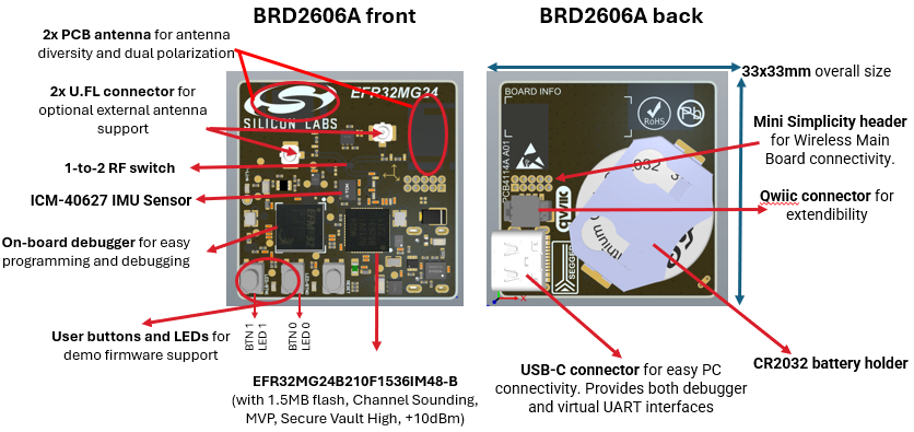
BRD2606A is a standalone board with everything you need for the demos, including a 6-axis IMU and a built-in SEGGER J-Link debugger for debugging the EFR32MG24 chip through a USB-C connector.
What You'll Need#
The walkthrough in this guide uses BRD2606A boards. Before you start, gather:
Two BRD2606A boards, one for the Initiator and one for the Reflector.
One USB-C cable to program the boards and keep the Initiator connected to your computer.
One CR2032 coin cell battery, or a second USB-C cable and USB power source, to power the Reflector during measurements.
A tape measure or laser distance meter.
An open area of at least 10 m with a clear line of sight, where you can keep people from walking through during measurements.
Simplicity Studio 6 (SSv6), installed and signed in, with the latest generally available Simplicity SDK (SiSDK) and the Channel Sounding example applications installed.
The CS Plotter, installed on the same host computer as SSv6.
In Part 1, you use prebuilt demos only. In Part 2, you create and build the SoC Initiator example and change one setting. In Part 3, you explore the same configuration and initialization path, then change procedure scheduling.
Part 1: Get Your First Reading#
In this part, you flash the prebuilt SoC demo firmware to one board at a time, power both boards, place them 2 m apart, and observe a live distance measurement.
Interested in NCP? This walkthrough uses only the SoC applications. For information about NCP applications, see NCP Mode Sample Applications in the Channel Sounding Developer's Guide.
Label the Boards#
Label one board I for Initiator and the other R for Reflector. You program the boards separately, and the labels help you keep track of their roles.
Flash the Reflector Demo#
Connect only the Reflector board (R) to your computer with the USB-C cable. Confirm that its power LED turns on.
Open SSv6 and confirm that the BRD2606A appears in the Devices view.
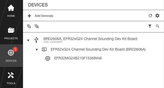
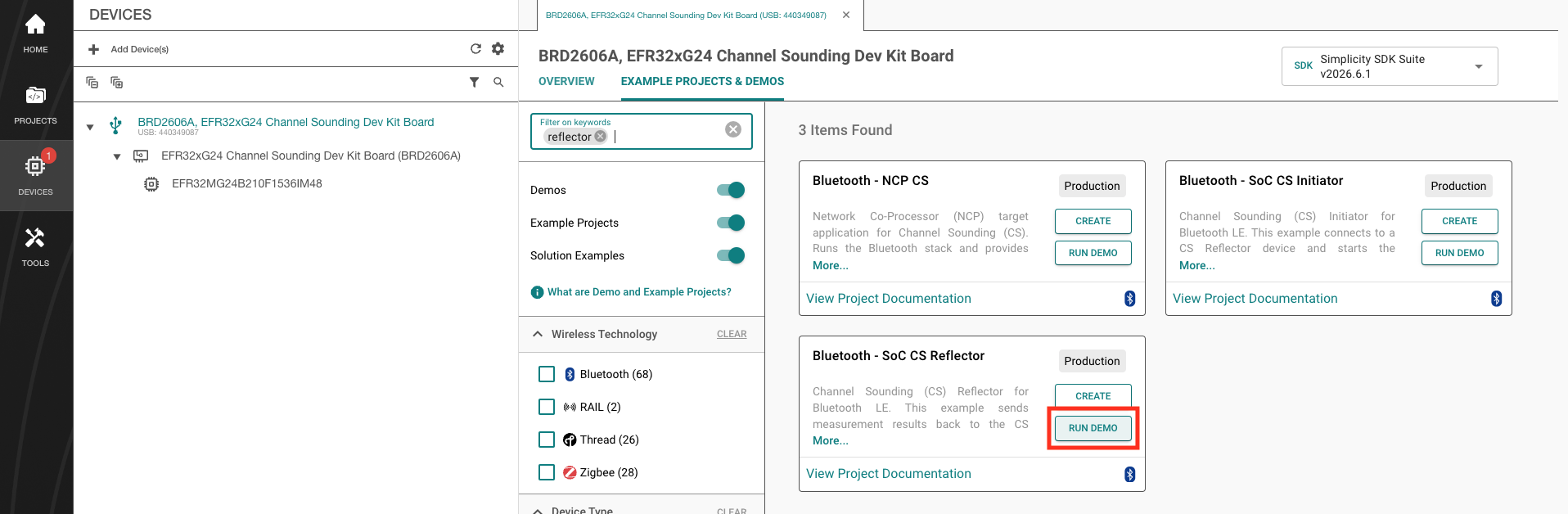
The prebuilt demo includes all requirements, so you do not need to create or build a project.
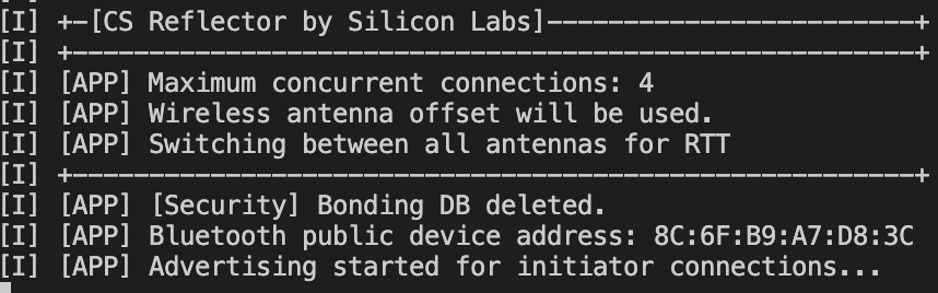
Open a serial terminal using 115200 8N1, press the reset button, and confirm that the Reflector starts advertising as CS RFLCT. Close the serial terminal, then disconnect the Reflector from the computer.
Flash the Initiator Demo#
Connect the Initiator board (I) to your computer with the USB-C cable. Confirm that its power LED turns on.
In the SSv6 Devices view, confirm that the BRD2606A appears.
Select the board, find the Bluetooth - SoC CS Initiator example project, and click RUN DEMO.
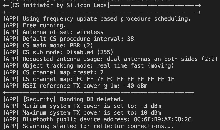
Open a serial terminal using 115200 8N1, press the reset button, and confirm that the Initiator starts scanning for a Reflector. Close the serial terminal so that the CS Plotter can access the Initiator's serial port. Keep the Initiator connected to the computer for the rest of the walkthrough.
Power the Reflector#
With the Initiator still connected to your computer, power the Reflector using one of these methods:
Insert a CR2032 coin cell battery into the holder on the back of the Reflector, following the polarity marking on the board.
Connect the Reflector to a USB power source with a second USB-C cable.
Confirm that the Reflector's power LED turns on. The Initiator should discover the Reflector and connect to it automatically.
Set Up the Measurement#
Use a tape measure or laser distance meter to place the boards 2.00 m apart in a clear area. Position the boards at the same height with their antennas facing each other (co-planar), oriented as in the image below.
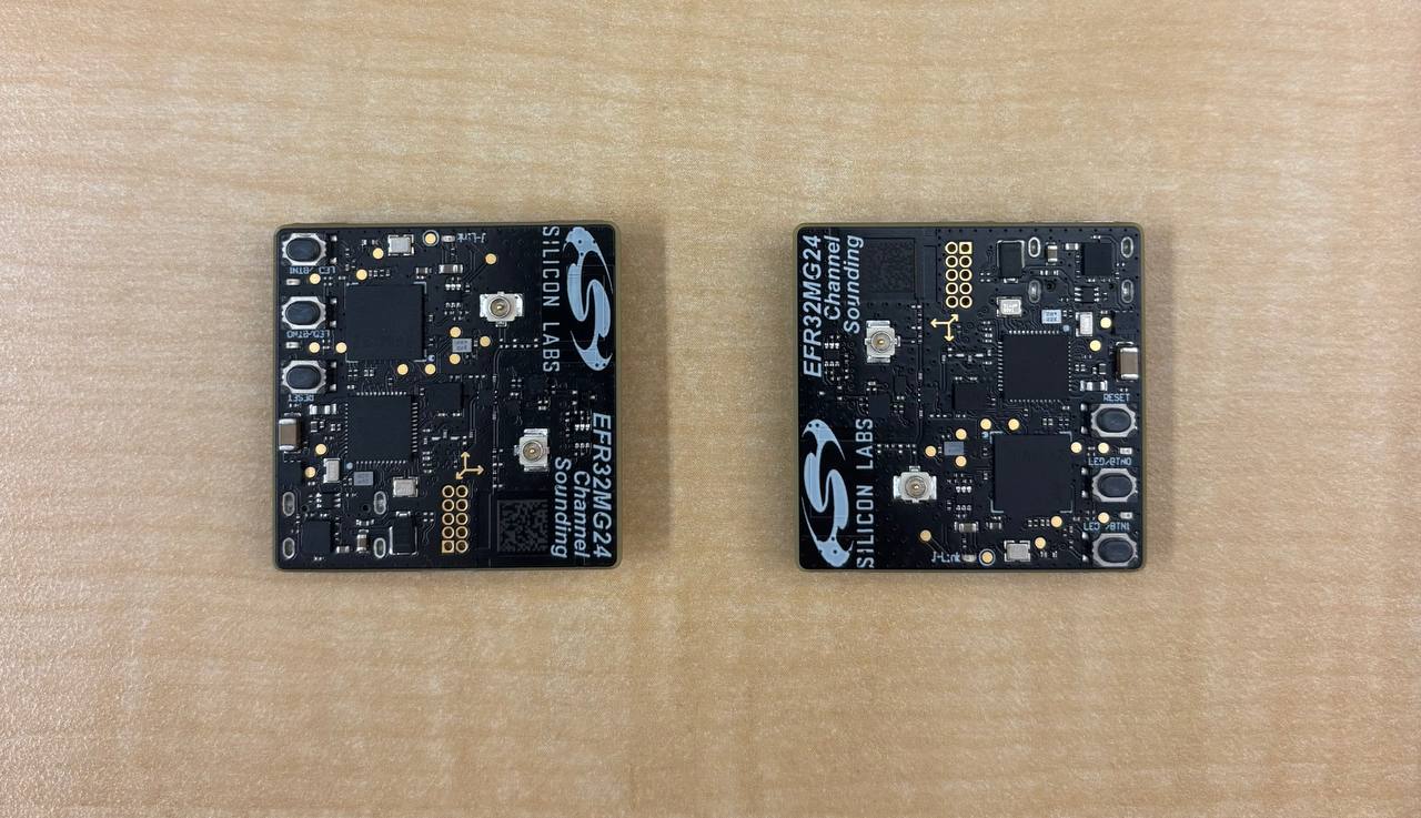
Use a wood or plastic surface when possible. Keep phones, laptops, metal objects, and people at least 0.5 m away from either board.
Using a metal table? Raise both boards 5-10 cm on a nonmetallic material such as cardboard.
Open the CS Plotter#
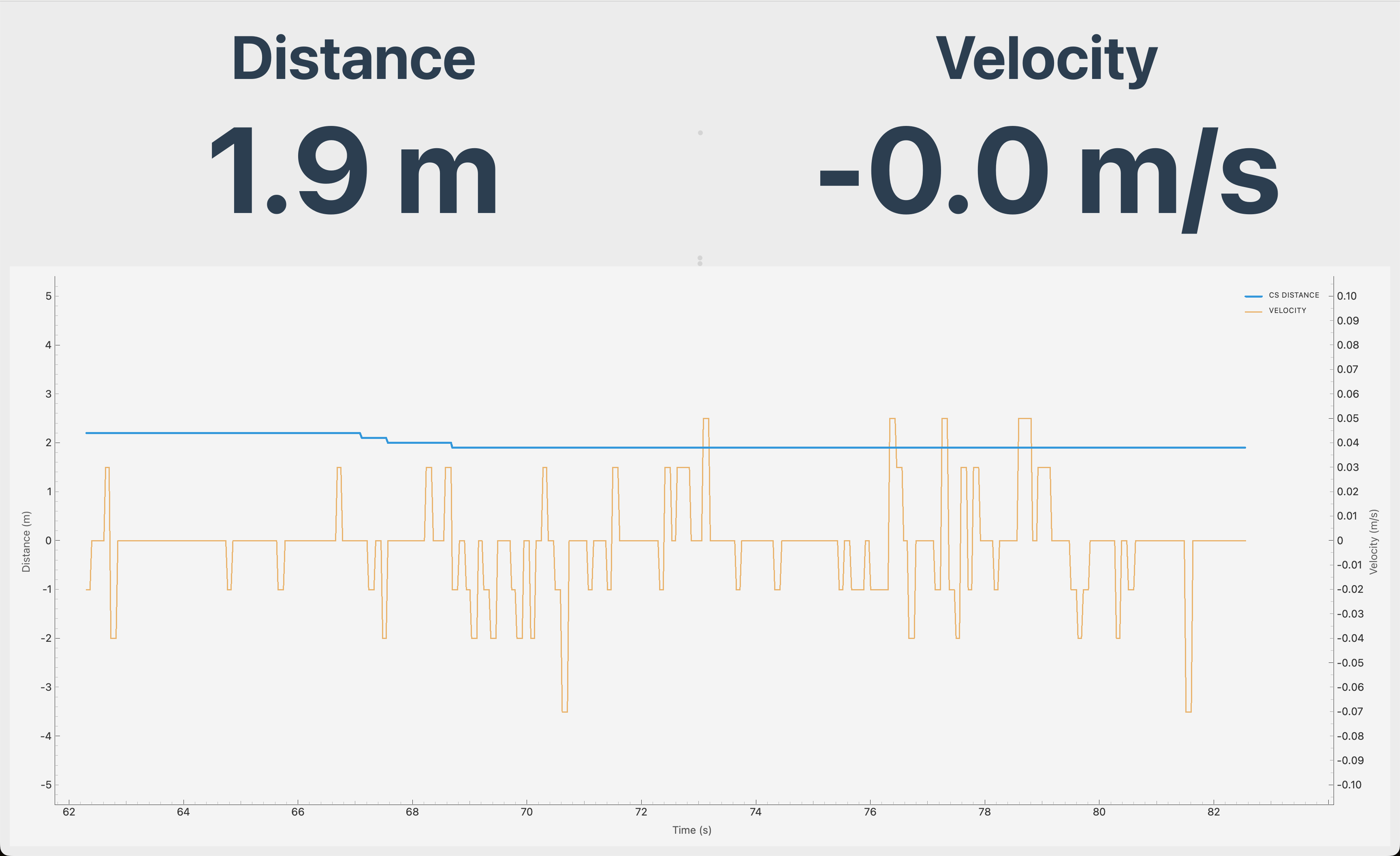
Launch the CS Plotter on the same computer as SSv6. Select the Initiator's serial port and start a new measurement session.
For installation and usage information, or to clone the tool, see the CS Plotter repository on GitHub.
The SoC Initiator demo uses the SL_RTL_CS_ALGO_MODE_TRACKING_LATENCY_OPTIMIZED algorithm by default, providing a fast-updating distance plot. The plot should begin updating, and the rolling average should settle near 2.0 m.
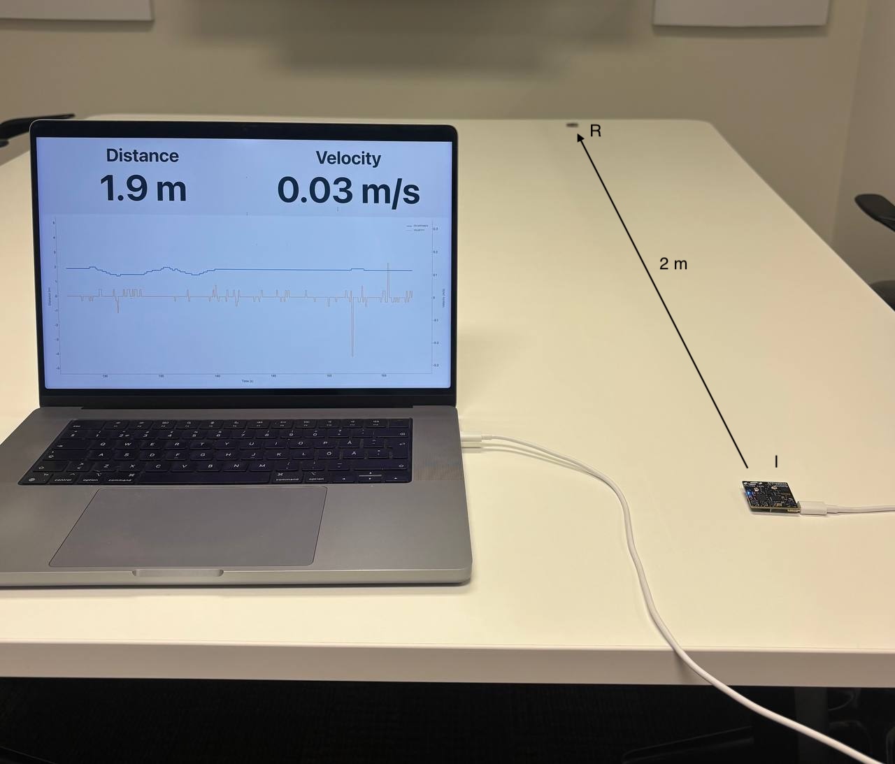
No data appears? Confirm that you selected the Initiator's serial port rather than the Reflector's.
The reading is far from 2.0 m? Wait 10-15 seconds for the first measurement window to converge. If it does not settle, move nearby metal objects, laptops, and other 2.4 GHz devices away from the setup.
Confirm the Baseline#
Without touching the boards, observe the distance measurement for 30 seconds.
The mean should be within 0.5 m of the measured 2.0 m separation.
The reading should vary by substantially less than 0.5 m.
This result is your baseline for the experiments in Part 2.
The reading varies significantly? Clear nearby metal objects, laptops, 2.4 GHz devices, and moving people from the test area, and then repeat the measurement.
You now have a working Channel Sounding distance measurement.
Part 2: See How It Behaves#
Now that you have a baseline, you can explore how distance, orientation, obstructions, nearby surfaces, and algorithm choice affect a Channel Sounding measurement. Compare each result with the 2 m baseline from Part 1.
Increase the Distance#
Move the Reflector to a measured distance of 5 m. Keep the boards at the same height with their antennas facing each other (co-planar), and observe the measurement for 20 seconds. Repeat the test at 10 m.
What to expect:
At 5 m, the mean should remain close to the measured separation, although the reading may vary more than it did at 2 m.
At 10 m, the behavior should be similar.
Accuracy and stability generally degrade as distance increases. Channel Sounding provides a distance estimate rather than a precision length measurement.
The reading suddenly changes? Check whether someone walked through the test area or whether a door, laptop, or another nearby object moved. Restore the environment and repeat the measurement.
Rotate the Reflector#
Return the boards to a 5 m line-of-sight setup. Keep the Initiator stationary and rotate the Reflector 90 degrees about its vertical axis, as seen in the image below.
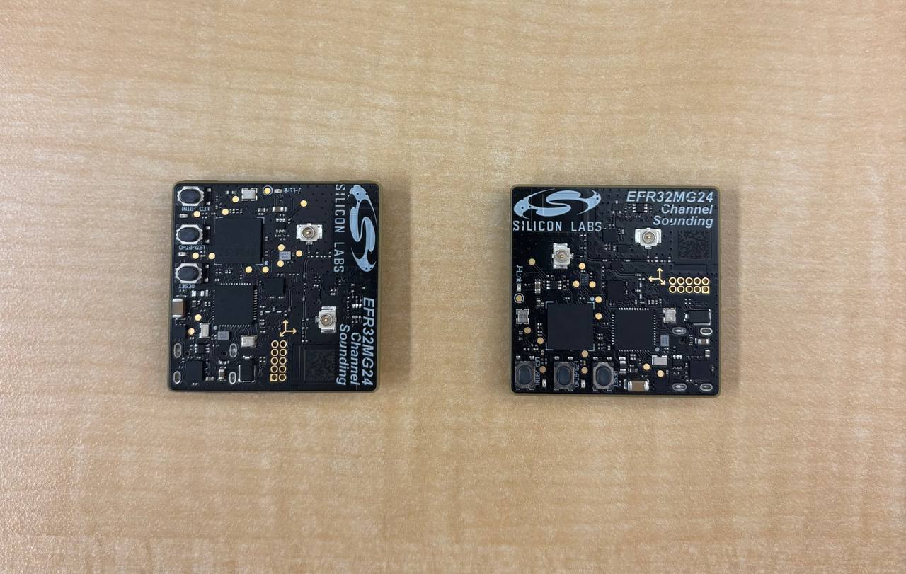
Observe the measurement for 20 seconds. Repeat at 180 degrees, and then return the Reflector to its original orientation.
The mean may shift and the reading may vary more as the board orientation changes. The size and direction of the change depend on the antenna pattern.
Optimizing the antenna, board placement, and enclosure design collectively maximizes the product's ranging performance.
Obstruct the Line of Sight#
With the boards 5 m apart, ask someone to stand directly between them for 20 seconds.
The estimated distance and its variation may increase. A human body absorbs and reflects 2.4 GHz signals, so an obstruction can bias the estimate even when the application continues to report a distance.
Add a Nearby Metal Surface#
Restore the line-of-sight path. Place a metal object, such as a closed laptop or baking sheet, about 20 cm from one board and parallel to the line between the boards. Observe the measurement for 20 seconds, remove the object, and observe for another 20 seconds.
The reading may vary noticeably, and the mean may shift in either direction. Nearby reflective surfaces create multipath, which is a major source of ranging error indoors. A product enclosure can have a similar effect.
Nothing changes? Move the metal object closer to the direct path between the boards and repeat the test.
Build the SoC Initiator Application#
The prebuilt demo is sufficient for the preceding experiments. To compare algorithm modes, create and build your own SoC Initiator application:
In the SSv6 Launcher, find the Bluetooth - SoC CS Initiator example.
Click CREATE and accept the default project settings.
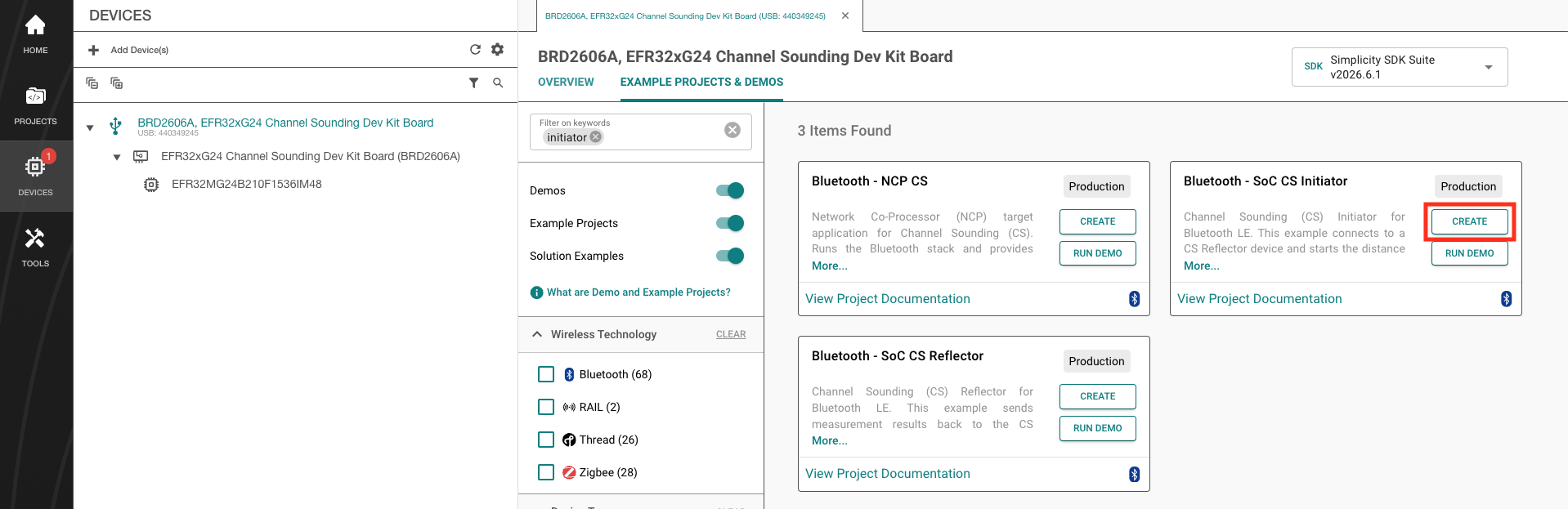
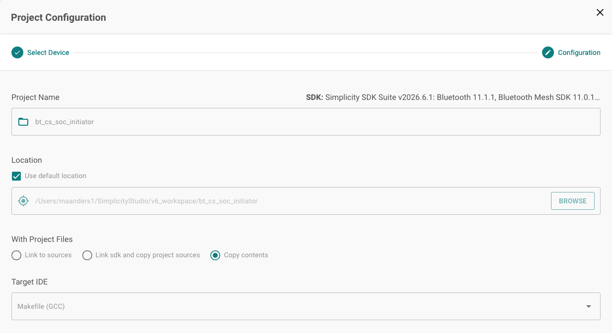
Leave the Reflector board running the prebuilt Bluetooth - SoC CS Reflector demo. No changes to the Reflector are needed for the rest of this guide.
Return the boards to the 2 m setup and repeat Confirm the Baseline. The application you built should produce a result comparable to the Part 1 baseline.
The build fails? Confirm that SSv6 has installed the required compiler toolchain, and then build the project again.
The result differs significantly from Part 1? Confirm that the Initiator and Reflector applications use the same SiSDK version.
Compare the Tracking Algorithms#
The default SL_RTL_CS_ALGO_MODE_TRACKING_LATENCY_OPTIMIZED mode prioritizes responsiveness. Compare it with SL_RTL_CS_ALGO_MODE_TRACKING_ACCURACY_OPTIMIZED, which applies more filtering to prioritize accuracy.
In the SoC Initiator project, open the config/cs_initiator_config.h. Change the algorithm mode from SL_RTL_CS_ALGO_MODE_TRACKING_LATENCY_OPTIMIZED to SL_RTL_CS_ALGO_MODE_TRACKING_ACCURACY_OPTIMIZED. Rebuild the project and flash the Initiator.
For each algorithm mode, run these tests:
Static test: Measure at 2 m and 10 m for 20 seconds at each distance. Compare the mean and how much the reading varies.
Moving test: Move the Reflector from 2 m to 10 m by walking briskly, and then return it back to 2 m. Repeat this movement twice and observe the live trace.
Algorithm mode | Static measurement | Moving measurement |
|---|---|---|
| More variation may be visible. | Responds quickly to movement with less lag. |
| The trace should be smoother. | The trace responds more slowly and rounds off abrupt changes in direction. |
The static test demonstrates the stability tradeoff, while the moving test demonstrates the latency tradeoff. Choose an algorithm based on whether your application values responsiveness or a more stable estimate. For more information, see RTL Algorithm Modes.
The algorithm mode is typically selected at build time. When you finish the comparison, restore SL_RTL_CS_ALGO_MODE_TRACKING_LATENCY_OPTIMIZED, rebuild the project, and flash the Initiator so that Part 3 begins from the original baseline.
The modes appear identical? Clean the project, rebuild it, and flash the Initiator again to ensure that the configuration change was included.
You now have a working project and practical experience with some of the environmental and configuration choices that affect Channel Sounding.
Part 3: Make It Yours#
You now have a working SoC Initiator project and an understanding of how the environment and algorithm mode affect its measurements. In this part, you will locate the main Channel Sounding configuration and initialization points, then change the procedure interval and observe the result.
Find the Channel Sounding Configuration#
In the SoC Initiator project, open config/cs_initiator_config.h.
Locate these settings in the header file and the corresponding generated macros:
Setting | Generated macro |
|---|---|
Procedure scheduling |
|
Minimum procedure interval |
|
Maximum procedure interval |
|
The application uses these defaults to populate a cs_initiator_config_t structure when it initializes the Initiator role.
// <o CS_INITIATOR_DEFAULT_PROCEDURE_SCHEDULING> Procedure scheduling
// <CS_PROCEDURE_SCHEDULING_OPTIMIZED_FOR_FREQUENCY=> Optimized for frequency update
// <CS_PROCEDURE_SCHEDULING_OPTIMIZED_FOR_ENERGY=> Optimized for energy consumption
// <CS_PROCEDURE_SCHEDULING_CUSTOM=> Use custom procedure scheduling
// <i> Set your custom connection and procedure intervals in the 'Custom Scheduling' section when selecting 'Use custom procedure scheduling' (CS_PROCEDURE_SCHEDULING_CUSTOM).
// <i> Default: CS_PROCEDURE_SCHEDULING_OPTIMIZED_FOR_FREQUENCY
#define CS_INITIATOR_DEFAULT_PROCEDURE_SCHEDULING CS_PROCEDURE_SCHEDULING_OPTIMIZED_FOR_FREQUENCY
// </h>
// <h> Custom scheduling
// <o CS_INITIATOR_DEFAULT_MIN_CONNECTION_INTERVAL> Minimum connection interval (in 1.25 ms steps) <6..3200>
// <i> Default: 6
#define CS_INITIATOR_DEFAULT_MIN_CONNECTION_INTERVAL 6
// <o CS_INITIATOR_DEFAULT_MAX_CONNECTION_INTERVAL> Maximum connection interval (in 1.25 ms steps) <6..3200>
// <i> Default: 6
#define CS_INITIATOR_DEFAULT_MAX_CONNECTION_INTERVAL 6For a complete list of settings, see Configuration Methods in the Channel Sounding Developer's Guide.
Trace Channel Sounding Initialization#
The Channel Sounding initialization flow spans the application and the Channel Sounding Initiator component. After the application establishes an encrypted Bluetooth connection to the Reflector, trace these calls in order:
In
app.c,sl_bt_cs_read_remote_supported_capabilities()obtains the Reflector's Channel Sounding capabilities.When capability discovery completes,
cs_initiator_create()creates a middleware instance for the connection and copies the application configuration and result callbacks into it.In
cs_initiator.c,sl_bt_cs_set_default_settings()enables the local Initiator role and applies its default controller settings.sl_bt_cs_create_config()creates the Channel Sounding configuration in the local and remote controllers.When configuration completes,
sl_bt_cs_set_procedure_parameters()applies the procedure timing and scheduling parameters.After Channel Sounding security and Ranging Service initialization complete, the component state machine calls
sl_bt_cs_procedure_enable()to start measurement procedures.
The application does not call sl_bt_cs_security_enable(). It waits for the peer-initiated Channel Sounding security procedure to complete before enabling measurement procedures.
For more information about these API calls, see the Bluetooth Channel Sounding API reference.
This flow connects the build-time settings in cs_initiator_config.h to the measurements displayed by the CS Plotter. For a broader walkthrough of the application, see Bluetooth - SoC CS Initiator.
Change the Procedure Interval#
The procedure interval is the number of Bluetooth connection events between consecutive Channel Sounding measurement procedures. For a fixed connection interval, increasing the procedure interval reduces the measurement update rate:
CS measurement frequency = 1 / (connection interval * procedure interval)
The default frequency-optimized scheduling preset chooses the procedure interval automatically. To experiment with the interval, configure custom scheduling:
In
cs_initiator_config.h, change Procedure scheduling to Custom.Set both the minimum and maximum procedure intervals to
100.Rebuild the project and flash the Initiator.
Return the boards to the 2 m baseline setup and observe the visualization for 30 seconds.
The distance should remain in approximately the same range as the Part 1 baseline, but the plot should be less responsive. You have changed how frequently measurements occur without changing the ranging algorithm.
The update rate does not change? Confirm that procedure scheduling is set to Custom. The minimum and maximum procedure interval settings are ignored when an optimized scheduling preset is selected.
Measurements stop or become unstable? Confirm that both interval values are
100, clean and rebuild the project, and flash the Initiator again.
When you finish the experiment, restore the frequency-optimized scheduling preset, rebuild the project, and flash the Initiator.
For additional scheduling constraints and examples, see CS Procedure Scheduling.
Troubleshooting#
If a measurement is missing, unstable, or inaccurate, record a BGAPI trace from the Initiator while reproducing the issue. The BGAPI trace captures BLE commands and events, including Channel Sounding data. Install the J-Link tools and the BGAPI Trace decoder as described in the BGAPI Trace guide before starting.
Keep the Initiator connected to the computer and the Reflector powered. Hold BTN0 on the Initiator while pressing Reset. When the orange LED turns on, release BTN0. The application waits for an RTT logger to connect.
Find the Initiator's J-Link serial number in the SSv6 Devices view. Replace
YOUR_J_LINK_IDin this command and start the logger:
JLinkRTTLogger -USB YOUR_J_LINK_ID -Device EFR32MG24BxxxF1536 -If SWD -Speed 4000 -RTTChannel 4 cs_trace.binReproduce the issue while the logger is running. Press any key in the logger's terminal to stop recording.
Decode the binary trace using the two
.xapifiles from the same SiSDK version used to build the Initiator. ReplaceYOUR_SISDK_PATHwith the path to that SDK:
bgapi_trace -f cs_trace.bin \
-a "YOUR_SISDK_PATH/bluetooth_le_host/api/sl_bt.xapi" \
-a "YOUR_SISDK_PATH/bluetooth_le_host/api/sli_bgapi_debug.xapi" \
> cs_trace.txtSend both cs_trace.bin and cs_trace.txt to your Silicon Labs sales representative or open a support ticket through Silicon Labs Community. Request a private thread before attaching logs or project files that contain sensitive information. Include:
What you expected to see and what happened instead, including a CS Plotter screenshot or representative readings.
The steps to reproduce the issue and the measured reference distances.
A photo or diagram showing the boards' positions, orientations, and nearby objects.
The SiSDK version, Initiator and Reflector firmware versions, and any Channel Sounding settings changed from the example defaults.
Where to Go Next#
Choose the next topic that matches your application:
Review the SoC sample application architecture.
Explore the available Channel Sounding capabilities and configuration options.
Review the known issues and limitations before designing a product.
You have completed the walkthrough: you can run a Channel Sounding measurement, evaluate its behavior, build the SoC Initiator application, locate its configuration and initialization flow, and make a controlled configuration change.