Calibration of Silicon Labs Distance Ranging#
This section discusses the theory and procedure of calibrating a Silicon Labs channel sounding SoC for accurate distance ranging. A wireless calibration should be performed per board design. Antenna recommendations should be adhered to.
The Bluetooth Core Spec requires that channel sounding implementations refer their measurements to their antenna port. This allows the system to be interoperable without concern for the circuit delays of implementations. Referring the PCT to the antenna is done by rotating complex numbers to compensate for the group delay. Extra delay is equivalent to extra distance and affects the accuracy of the system. The delays can be separated into the internal radio group delay and the board and antenna group delay.
The internal radio group delay is the delay from the RF and digital filter circuits. Silicon Labs has compensated for the variation of this delay over RF gain. This is automatically applied, and no further compensation is needed.
The board delay can be further divided into the delay from the matching network and delay from traces or cabling. The recommended matching network for the EFR32XG24 was simulated over its component tolerances. The notes below the figure show that, while there is a phase shift, the group delay remains relatively constant. Further analysis shows that the component tolerance should contribute only up to +/- 0.05 m.
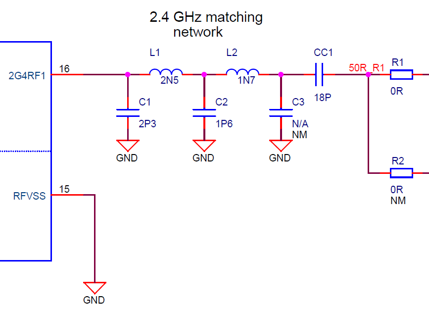
C1: 2.3pF +/-0.05pF Murata GRM0335C1H2R3WA01
L1: 2.5nH +/-0.05nH Murata LQP03HQ2N5W02
C2: 1.6pF +/-0.05pF Murata GRM0335C1H1R6WA01
L2: 1.7nH +/-0.05nH Murata LQP03HQ1N7W02
C3: No population
CC1: 18pF +/-2% Murata GJM0335C1E180GB01
The traces and cabling delay consists of the propagation through the RF traces and coaxial cable if an off-board antenna is used. Direct measurement of these delays is not necessary, as the delays are additive and are captured in the wireless calibration. The speed of propagation through these materials is slower than the speed of light in a vacuum. This ratio is the velocity factor and varies widely from 0.6 – 0.9 depending on the construction and geometry. This explains why when inserting a cable of physical length L, the measured distance will shift by L / VF. For designs with multiple antenna paths, the calibration should be run once per antenna path.
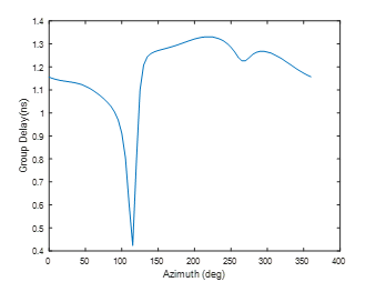
The last component is the antenna contributing delay. The plot below shows the group delay over azimuth for a printed inverted F antenna. With a group delay of 1-1.5 ns, the antennas are contributing approximately 0.75 m of offset. Due to the antenna distance offset, Silicon Labs recommends a wireless distance offset calibration, as a cabled test will not include this significant offset.
Calibration Procedure#
This section describes how perform the wireless calibration procedure.
The measurement should be configured for maximum measurement time T_PM=40 us, and at least two mode0 steps. It is preferable to have the entire channel sweep contained in a single subevent. This is the default configuration for the provided sample application. It is acceptable if these parameters deviate from the configuration used in the field. The purpose is to use the highest accuracy configuration for configuration.
The devices should be elevated off the ground by at least 1 m. The environment should be open to avoid multi-path effects, i.e., a large room. Avoid having objects in the line-of-sight path.
Prepare two devices for wireless distance measurements.
Set the distance offset calibration to 0 m with the API sl_bt_cs_set_antenna_configuration.
Reflash the devices.
Run the measurements and algorithm for 100 distance measurements. Record the median of the distribution.
Repeat for at least 5 distances between 1 and 20 m.
Calculate a linear regression of the expected distance vs measured distance. The distance offset is the y-intercept.
Set the distance offset calibration to half of the distance offset. Reflash the devices.
Repeat step 4 and 5 making measurements.
Verify the distance error is centered around zero.