Using Hardware Configurator#
Simplicity Studio® 5 (SSv5)'s Hardware Configurator for 8-bit devices uses the Configurator perspective. This perspective is tailored specifically for use with Hardware Configurator to initialize MCU peripherals. Special views in this perspective allow peripheral registers to be configured.
The available editors in a Configurator project are as follows:
Peripherals: Used to configure hardware peripherals such as ADCs, Timers, LEUART, PCAs, and so on.
Port I/O: Used to configure the pin locations, crossbar, and port pins. This editor is open by default for a new project.
Mode Transitions: Used to define different MCU peripheral initialization states, such as DefaultMode, RESET, and other optional modes (example: LowPower mode). This editor can also be used to define transitions between states.
The Hardware Configurator automatically validates register configuration values. Occasionally changes to the configuration can cause errors or warnings. These clear as soon as the cause is addressed.
Peripherals#
Use the Peripherals tab to configure hardware peripherals like the ADC, comparators, or timers. To configure a peripheral, click the peripheral icon. This selects the peripheral and opens it in the Properties view. Properties can either have a drop-down menu with the available selections or a text input box for a numeric or text field. Properties that are grayed out are read-only. These properties typically provide more information about the configuration of a peripheral. After making a selection for a property, click away from the property or press Enter to ensure the property value change occurs.
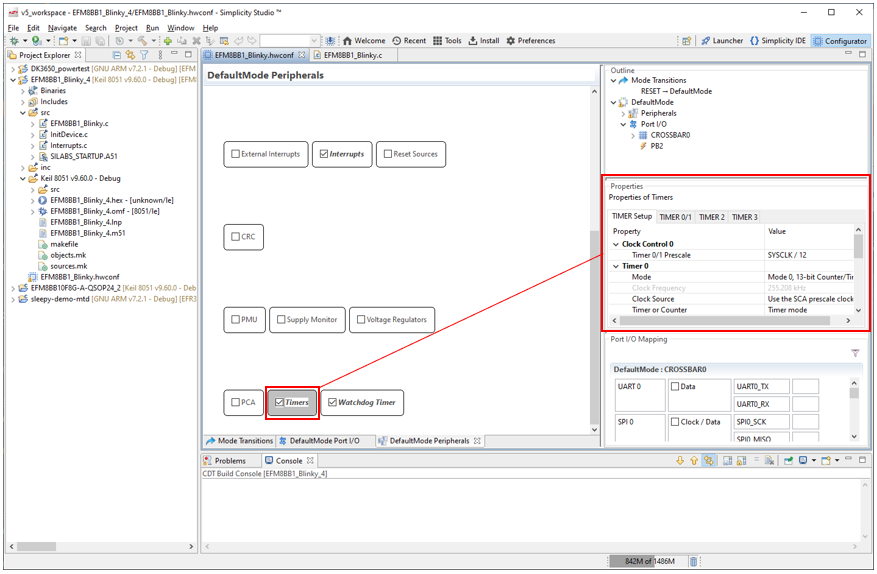
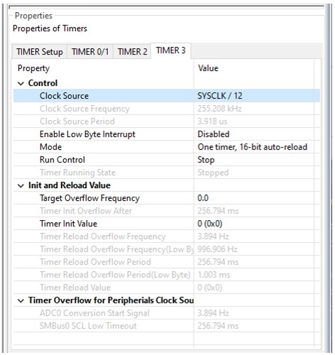
For example, click the Timers peripheral to display the timer properties in a tabbed view. The Timer 3 tab has several properties that can be modified, like Clock Source, Mode, and Target Overflow Frequency. Modifying any of these properties will update the Timer Reload Overflow Period and Timer Reload Overflow Frequency read-only properties, which display the calculated overflow time based on the Target Overflow Frequency and the Clock Source settings. These read-only fields and calculators depend on the Mode and Run Control state. Calculators for reload value are for auto-reload mode.
Note: Peripherals will not have code generation enabled unless the peripheral checkbox is checked.
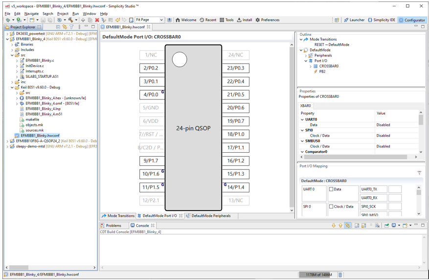
Port I/O#
The Port I/O tab displays a package drawing for the selected device. This drawing updates to display pin assignments as peripherals are enabled on the crossbar or peripherals with fixed pin assignments are enabled. For fixed pin assignments, the associated peripheral must be enabled in order for the fixed pin function to appear on the Port I/O tab. Changes are shown in blue until the file is saved.
For example, on the Peripherals tab make sure the ADC0 module is checked. On the port I/O tab, in the Outline view select ADC0, in Properties change Enable ADC to Enabled, and select a Positive Input pin (in this example P1.3). This displays the ADC_IN fixed signal on the selected pin in the drawing.

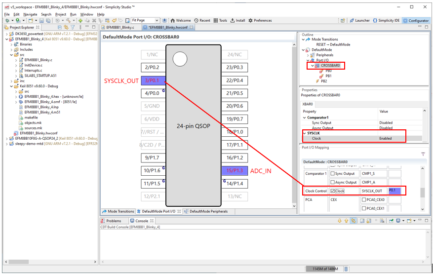
To enable a peripheral on the crossbar, on the Peripherals tab enable a peripheral for code generation (in this case Clock Control). On the Port I/O tab, in the Outline view click CROSSBAR0, and in the Port I/O Mapping view check the corresponding signal. This changes the corresponding property to Enabled.
To configure a pin’s properties, click the pin in the package drawing and select the desired pin property settings. If configuring a device with a crossbar, a pin can be skipped by right-clicking the pin and selecting Skip in the context menu or changing the Skip property setting.
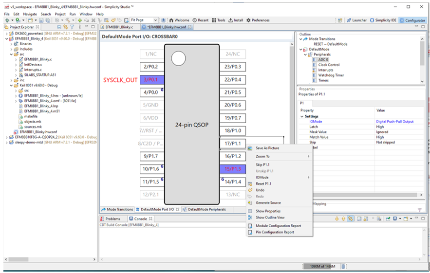
Similarly, I/O mode can be selected by right-clicking the pin and selecting IOMode or changing the IOMode property setting.
On all devices, multiple pins can be selected by holding Ctrl or Shift and selecting the desired pins or holding the left mouse button and dragging over a group of pins. With multiple pins selected, the property changes made in the Properties view or context menu apply to all pins. To reset a pin to its default state, right-click the pin and select Reset.
Mode Transitions#
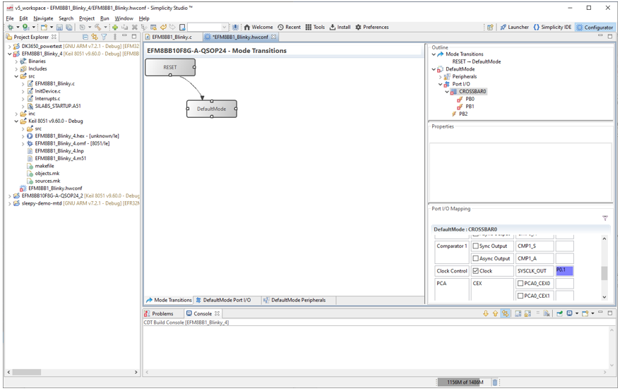
Modes define different states of peripheral configurations. For example, an application may use two configurations of the ADC and Timer 2 with different input pins and sampling rates. These two configurations can be treated as separate modes with separate initialization sequences. The movements between these modes are called transitions. By default, each project contains one DefaultMode mode. The reset state exists only to indicate the transition from RESET to DefaultMode and is not a full mode.
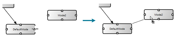
To add a new mode, right-click either the Mode Transitions tab or the Outline view and select Create Mode from Reset. Right-clicking an existing mode also enables cloning that mode with the Clone Mode option. To add a transition from one mode to another, hover over one of the four white handles on a mode until the mouse cursor changes, hold down left mouse button, and drag to the end mode of the transition. A Peripherals and Port I/O pair of tabs are added for each mode in the project.
After reset, call the mode transition enter_DefaultMode_from_RESET() to apply the DefaultMode settings. In most cases this will be the first transition in the application code.
Adding a transition generates a corresponding function that application firmware can call to initiate the transition between modes. For example, with DefaultMode as the originating mode going to Mode2:
enter_Mode2_from_DefaultMode(void)
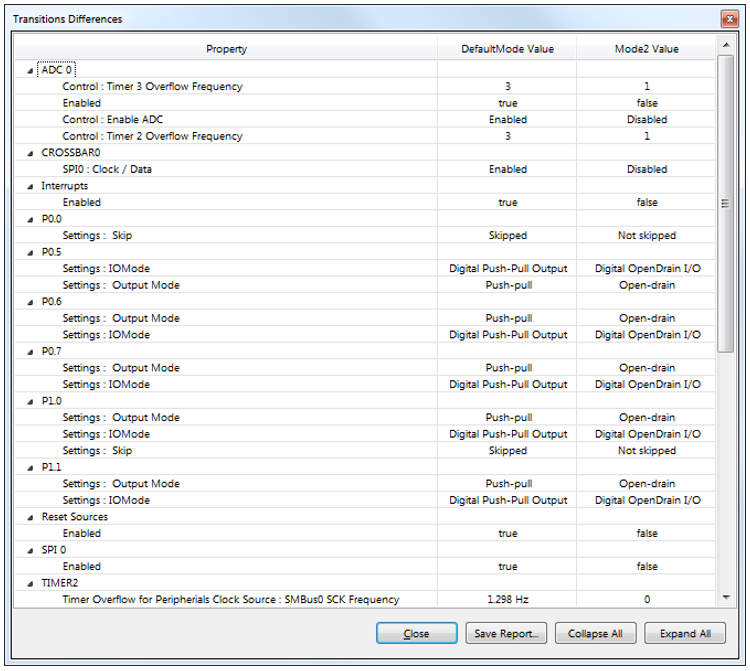
This function then calls all of the functions that configure the peripherals for the mode. Hardware Configurator generates only the transitional code from peripheral to peripheral between modes. For example, if only the timer reload value and ADC input mux selection differ, then those are the only two properties touched by the transition code. To see the differences between two modes, right-click the mode transition and select Show Differences. This provides a report of all the different property values between the modes on a module-by-module basis.
Transitions can be added in both directions using the same method as the original mode transition.
To delete a mode transition, select the arrow and press Delete or right-click the arrow and select Delete transition.
Transition functions will not modify the state of the global interrupt enable (EA) on EFM8 or C8051 devices. Transitions assume that interrupts are disabled (that is, global interrupt enable bit EA = 0) or that any enabled interrupts will not interact with any changes made during the transition. Transition functions do not clear interrupt flags, to ensure that no information is lost during reconfiguration. If having these flags set will cause an issue in firmware operation, firmware must clear these interrupt flags before calling the transition function.
Transition functions also assume that any peripherals being updated are not active. For example, firmware should stop a timer before calling a transition function that changes the timer configuration and restart the timer after the transition completes.
It is possible to change the configuration order of a set of peripherals by creating multiple modes with multiple transitions. For example, to configure Timer 2 before the ADC during a mode transition that would normally put the ADC first, create a mode to handle the Timer 2 changes and a mode to handle the ADC changes. Firmware can then call the Timer2 mode transition function first, followed by the ADC transition function.
Errors and Warnings#
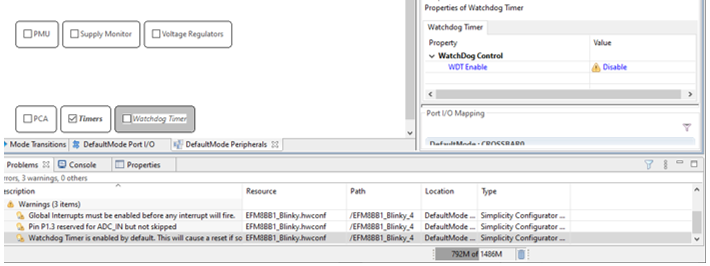
The Hardware Configurator automatically validates register configuration values and displays any errors, warnings, or information items in the Problems view. Double-clicking an entry displays the property that raised the problem in the Properties view. Any peripherals that contain a warning or error are highlighted in yellow (warning) or red (error), and the associated property has a corresponding warning or error icon.
Once the highlighted property is updated, the associated warning or error will disappear from the Problems view, indicating that the problem has been solved.
All newly created projects will have a warning regarding the Watchdog Timer, since it’s enabled after a reset and must be handled in application code or disabled. If a warning or error doesn’t apply to the project, it can be temporarily deleted from the project by right-clicking the entry in the Problems view and selecting Delete. Closing and reopening the .hwconf file regenerates any deleted warnings or errors.
Code Generation#
To generate code for a peripheral, check the checkbox for that peripheral in the Peripherals tab. Saving the project automatically generates code for all selected peripherals and port pins. This code generates into the InitDevice.c, InitDevice.h, and Interrupts.c files.
Each hardware register has a section in the InitDevice.c file tagged with the register name and register description. For example, the P1 register area is as follows:
// $[P1 - Port 1 Pin Latch]
// [P1 - Port 1 Pin Latch]$These tags indicate that everything in between is automatically generated, so any code added manually between these tags will be deleted on the next Hardware Configurator project save. Code can be added in between these tags, however, and this code will not be overwritten.
// $[P1 - Port 1 Pin Latch]
P1 = 0x00; // This code is not safe, and Configurator will overwrite it
// [P1 - Port 1 Pin Latch]$
P1 = 0x00; // This code is safe from Configurator automatic code generation
// $[P1MASK - Port 1 Mask]
// [P1MASK - Port 1 Mask]$For registers that are modified from their reset value or the value in the previous mode, the tags include comments that update based on the settings for the register. For example, setting P1.0 to push-pull on an EFM8 or 8-bit MCU generates the following:
// $[P1MDOUT - Port 1 Output Mode]
/*
// B0 (Port 1 Bit 0 Output Mode) = PUSH_PULL
// (P1.0 output is push-pull.)
// B1 (Port 1 Bit 1 Output Mode) = OPEN_DRAIN
// (P1.1 output is open-drain.)
// B2 (Port 1 Bit 2 Output Mode) = OPEN_DRAIN
// (P1.2 output is open-drain.)
// B3 (Port 1 Bit 3 Output Mode) = OPEN_DRAIN
// (P1.3 output is open-drain.)
// B4 (Port 1 Bit 4 Output Mode) = OPEN_DRAIN
// (P1.4 output is open-drain.)
// B5 (Port 1 Bit 5 Output Mode) = OPEN_DRAIN
// (P1.5 output is open-drain.)
// B6 (Port 1 Bit 6 Output Mode) = OPEN_DRAIN
// (P1.6 output is open-drain.)
// B7 (Port 1 Bit 7 Output Mode) = OPEN_DRAIN
// (P1.7 output is open-drain.)
*/
P1MDOUT = P1MDOUT_B0 PUSH_PULL | P1MDOUT_B1 OPEN_DRAIN | P1MDOUT_B2 OPEN_DRAIN
| P1MDOUT_B3 OPEN_DRAIN | P1MDOUT_B4 OPEN_DRAIN | P1MDOUT_B5 OPEN_DRAIN | P1MDOUT_B6 OPEN_DRAIN | P1MDOUT_B7 OPEN_DRAIN;
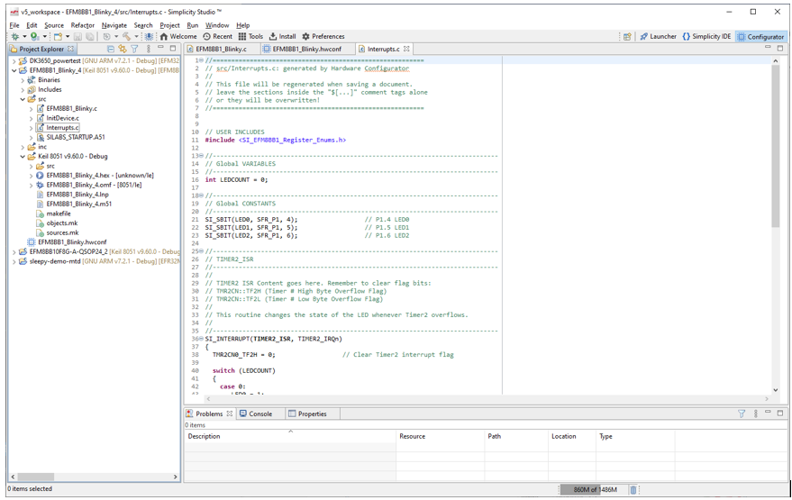
// [P1MDOUT - Port 1 Output Mode]$Interrupts#
The Hardware Configurator creates an interrupts.c file containing interrupt prototypes whenever interrupts are enabled and the project is saved. Hardware Configurator generates the prototype if it is not present, but does not overwrite existing prototypes. This protects any application code written in the prototypes from being accidentally modified or deleted. The comments above the prototypes list any flags in the modules that may need to be cleared by application code after the interrupt triggers.