Inter-Integrated Circuit (I²C) Debugging and Error Handling#
Use this section to troubleshoot Inter-Integrated Circuit (I²C) on SiWx917. You’ll perform quick hardware checks, debug on the development kit, capture SDA/SCL with a logic analyzer, and apply driver-level recovery steps while interpreting common error codes.
Common Debugging Tips#
See the official troubleshooting guide for application-level debugging: WiSeConnect Debugging Guide.
Debugging I²C Connections#
Debugging typically starts with wiring and compatibility checks, then moves to tool-assisted verification with Simplicity Studio and a logic analyzer.
1. Visual Inspection and Connection Checklist#
Before running software tests, verify:
SDA/SCL wiring is correct between the leader (controller) and follower (target).
Pull-up resistors are present on both lines (commonly 4.7 kΩ–10 kΩ; lower values for higher speeds/longer buses).
Common ground connects all boards.
I/O voltage levels are compatible on both sides (for example, 3.3 V or 1.8 V).
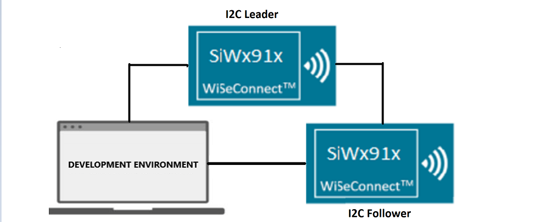
2. Interfacing with Si91x Development Kits (Leader/Follower)#
Si91x development kits make I²C bring-up straightforward. Use one board as the leader (controller) and another as the follower (target).
Setup steps:
Connect SDA to SDA and SCL to SCL between boards.
Ensure a shared ground and power both boards.
Use Simplicity Studio to flash and debug firmware on each board.
Run I²C transactions; monitor with a logic analyzer and Simplicity Studio’s debug tools.
For custom followers, confirm the address and timing (speed/clock stretching) match the leader’s configuration.
Example setup diagram:
3. Using a Logic Analyzer#
A logic analyzer lets you view I²C waveforms and decoded protocol frames.
Steps:
Attach probes to SDA and SCL.
Enable I²C protocol decoding; set a suitable threshold and a sample rate of at least 1 MHz.
Capture typical transactions and verify:
START/STOP conditions
Address + R/W and subsequent ACK/NACK
Data bytes and expected repeated START (when required)
Clock stretching behavior
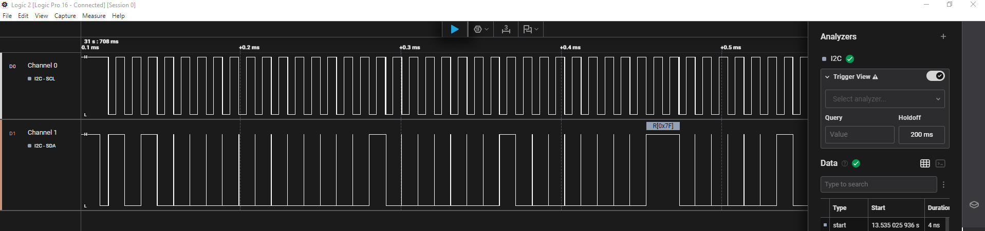
Example capture:
The following capture (Saleae Logic Pro 16) shows I²C between two Si91x boards configured as leader and follower using a blocking-transfer example.
4. Simplicity Studio + Logic Analyzer Workflow#
Correlate firmware execution with captured bus activity:
Open Simplicity Studio and switch to the Debug perspective.
Program firmware and connect the logic analyzer to SDA/SCL.
View I²C signals in the analyzer app (or Studio plug-in, if available).
Place breakpoints to align code paths with on-wire frames.
Error Code Handling#
The I²C driver returns standardized status codes from APIs.
The driver returns sl_i2c_status_t values. Common ones include:
Status | Meaning |
|---|---|
| Operation completed successfully |
| Not-acknowledge received |
| Bus error detected |
| Transfer complete |
| Controller is idle |
Use these to identify issues such as bus lockups, mis-wired pins, or timing mismatches.
If the peripheral enters an error or undefined state (for example, missed ACK, contention, or after a power transition), reset the driver:
sl_i2c_driver_deinit();
sl_si91x_i2c_init();Additional Debugging Tips#
Use these practices to improve debugging:
Print error codes and status messages in firmware with
DEBUGOUT.Check for bus contention, shorted lines, or missing pull-ups if communication fails.
Diagnose timing issues, missed ACKs, or unexpected NACKs with a logic analyzer.