Enhanced General-Purpose Input/Output (EGPIO) Initialization and Configuration#
This section describes how to initialize and configure enhanced general-purpose input/output (EGPIO) pins on SiWx917 devices by using the WiSeConnect software development kit (SDK) in Simplicity Studio.
You learn how to enable GPIO components, configure high-performance (HP), ultra-low-power (ULP), and ultra-ultra-low-power (UULP) GPIO instances, and verify basic input and output behavior.
Note: For detailed development guidance, see WiSeConnect Documentation.
Startup Sequence#
GPIO development for SiWx917 devices follows four main stages:
Create or open a project in Simplicity Studio.
Enable the GPIO software component.
Build and flash the project to your board.
Configure and control GPIO pins in your application.
Each stage is described in the sections below.
Step 1. Create or Open a Project#
Launch Simplicity Studio.
Create a new project or open an existing one for your SiWx917 device.
In the Example Projects and Demos section, select one of the following example projects:
sl_si91x_gpio_examplesl_si91x_gpio_group_examplesl_si91x_gpio_ulp_examplesl_si91x_gpio_uulp_example
Connect the SiWx917 radio board to enable automatic detection.
Click Create to import the example into your workspace.
Review the generated project documentation (for example,
readme.md) to understand example functionality.
Typical Project Directory Structure:
autogen/ // Auto-generated files (headers, linker scripts)
config/ // Platform configuration headers
resources/ // Documentation and image assets
simplicity_sdk/ // Gecko SDK platform layer
wiseconnect3_sdk/ // WiSeConnect SDK components
app.c / app.h // Application source and header
main.c // Entry point
readme.md // Example documentation
sl_si91x_gpio_example.slcp // Main configuration file
sl_si91x_gpio_example.pintool // Pin Tool configurationStep 2. Add the GPIO Component#
To enable GPIO support:
Open the project
.slcpfile.Select the Software Components tab.
Search for GPIO and click Install to add the corresponding component.
This step ensures that GPIO driver code and configuration options are included in your build.
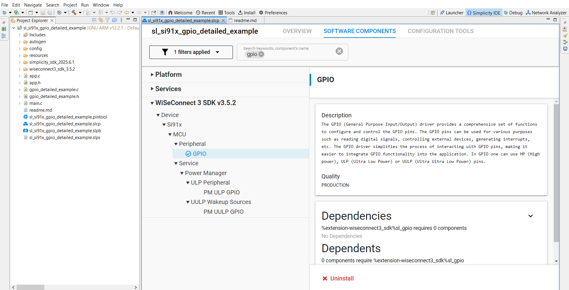
Figure: Adding the GPIO component in Simplicity Studio.
Step 3. Build, Flash, and Test#
Build your project in Simplicity Studio.
Flash the firmware to the SiWx917 board.
Open the VCOM Console or a terminal program (such as PuTTY) to view log output.
Verify GPIO behavior such as toggling, reading inputs, or responding to interrupts.
Step 4. GPIO Initialization and Configuration in Code#
After the project is set up, initialize and configure GPIOs in your application source code.
The following example shows how to initialize the GPIO driver and configure a pin as an output.
#include "sl_si91x_driver_gpio.h"
static sl_si91x_gpio_pin_config_t gpio_config = {
{ SL_SI91X_GPIO_10_PORT, GPIO_PIN_NUMBER10 },
GPIO_OUTPUT
};
void gpio_init_example(void)
{
sl_status_t status;
// Initialize GPIO driver
status = sl_gpio_driver_init();
if (status != SL_STATUS_OK) {
printf("GPIO initialization failed: %lu\n", status);
return;
}
// Configure pin direction and mode
status = sl_gpio_set_configuration(gpio_config);
if (status != SL_STATUS_OK) {
printf("GPIO configuration failed: %lu\n", status);
return;
}
// Toggle the pin periodically
while (1) {
sl_gpio_driver_toggle_pin(&gpio_config.port_pin);
printf("Toggled GPIO successfully\n");
sl_si91x_delay_ms(1000);
}
}This sequence initializes the GPIO driver, configures the pin direction, and toggles the pin every second.
Programming Sequences#
Single-Port GPIO Configuration#
Use this sequence when configuring one GPIO pin.
Step 1. Initialize Driver#
sl_gpio_driver_init();Step 2. Configure the Pin#
sl_si91x_gpio_pin_config_t pin_cfg = { {PORT, PIN}, GPIO_OUTPUT };
sl_gpio_set_configuration(pin_cfg);Step 3. Set the Pin Mode (Optional)#
sl_gpio_driver_set_pin_mode(&pin_cfg.port_pin, MODE, OUTPUT_VALUE);Step 4. Control the Pin#
sl_gpio_driver_set_pin(&pin_cfg.port_pin);
sl_gpio_driver_clear_pin(&pin_cfg.port_pin);
sl_gpio_driver_toggle_pin(&pin_cfg.port_pin);Multi-Port GPIO Configuration#
For multiple pins, loop through an array of configurations.
Step 1. Initialize the Driver#
sl_gpio_driver_init();Step 2. Configure Multiple Pins#
for (int i = 0; i < NUM_PINS; i++) {
sl_gpio_set_configuration(pin_cfg_array[i]);
}Step 3. Toggle All Pins#
for (int i = 0; i < NUM_PINS; i++) {
sl_gpio_driver_toggle_pin(&pin_cfg_array[i].port_pin);
}GPIO Interrupt Configuration#
Use GPIO interrupts for event-driven input detection.
Step 1. Initialize the Driver#
sl_status_t status = sl_gpio_driver_init();Step 2. Configure Interrupt Pins#
sl_si91x_gpio_pin_config_t pin_cfg = { { PORT, PIN }, GPIO_INPUT };
sl_gpio_set_configuration(pin_cfg);Step 3. Configure a Group Interrupt#
uint8_t pins[] = { PIN1, PIN2 };
uint8_t ports[] = { PORT1, PORT2 };
uint8_t polarity[] = { GPIO_POLARITY_0, GPIO_POLARITY_0 };
sl_si91x_gpio_group_interrupt_config_t group_cfg;
group_cfg.grp_interrupt = GROUP_INT_1;
group_cfg.grp_interrupt_cnt = 2;
group_cfg.and_or = GPIO_AND;
group_cfg.level_edge = GPIO_LEVEL;
memcpy(group_cfg.grp_interrupt_pin, pins, sizeof(pins));
memcpy(group_cfg.grp_interrupt_port, ports, sizeof(ports));
memcpy(group_cfg.grp_interrupt_pol, polarity, sizeof(polarity));
status = sl_si91x_gpio_driver_configure_group_interrupt(
&group_cfg, group_interrupt_callback);Additional Configuration Options#
You can customize pin behavior further using driver APIs:
Function | Description |
|---|---|
| Adjusts drive strength. |
| Changes pin mode. |
| Sets pin LOW. |
| Sets pin HIGH. |
| Toggles the current value. |
Testing and Validation#
To verify GPIO functionality:
Monitor serial logs during pin operations.
Use an oscilloscope or logic analyzer to confirm signal timing.
Validate behavior across power states such as PS2 and PS4.
Test interrupt responsiveness using buttons or sensor inputs.