Inter-IC Sound (I²S) Initialization and Configuration#
The WiSeConnect software development kit (SDK) provides a unified Inter-IC Sound (I²S) driver application programming interface (API) for SiWx917 devices. The driver supports multiple I²S instances with configurable operating modes, transfer types, and power-management features.
This guide walks you through the complete initialization and configuration process for I²S communication, from project setup to verification on hardware.
Step 1. Create or Open a Project#
Launch Simplicity Studio.
Create a new SiWx917 project or open an existing one.
For a quick start, start from a WiSeConnect I²S example:
sl_si91x_i2s_primarysl_si91x_i2s_secondarysl_si91x_i2s_loopbacksl_si91x_ulp_i2s
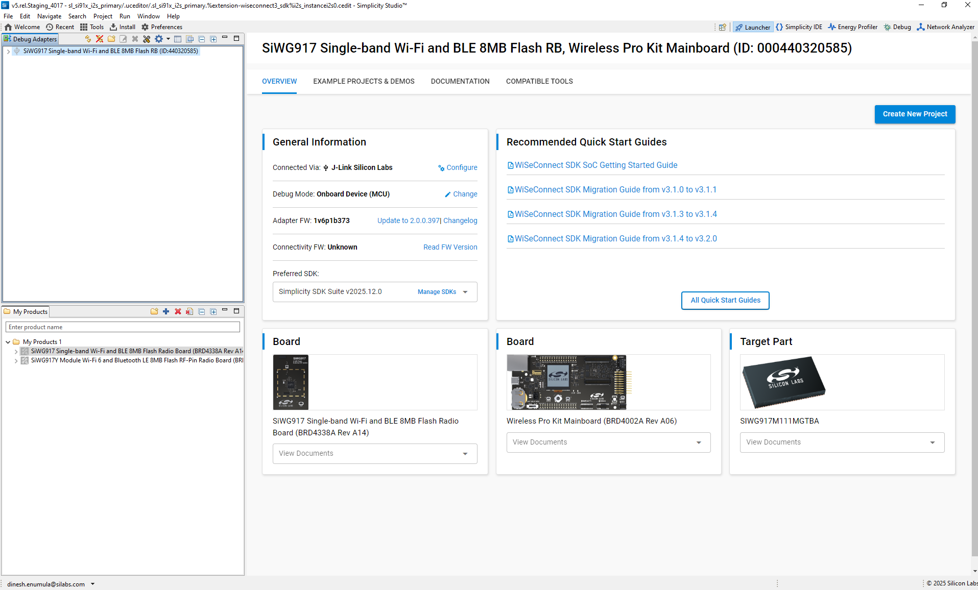
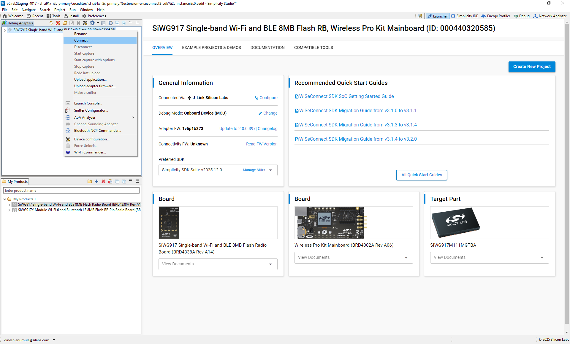
Connect the SiWx917 radio board. Simplicity Studio detects it automatically and shows it in Connected Devices.
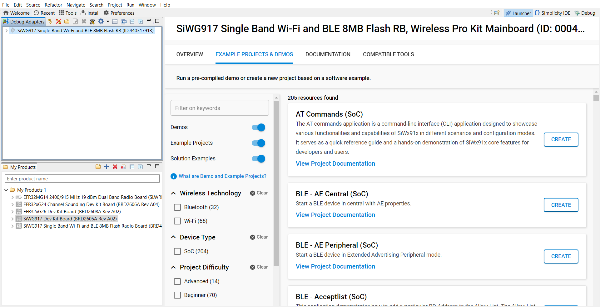
Figure: Board detection in Simplicity StudioFrom Example Projects and Demos, search for
I2S, select an example, and click Create.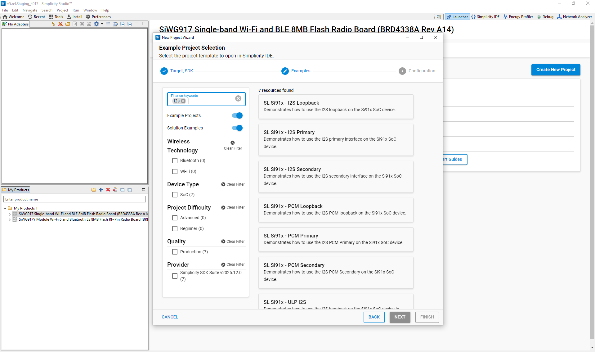
Figure: Searching for I²S example projects in Simplicity StudioReview the example’s
readme.mdfor supported hardware and expected console output.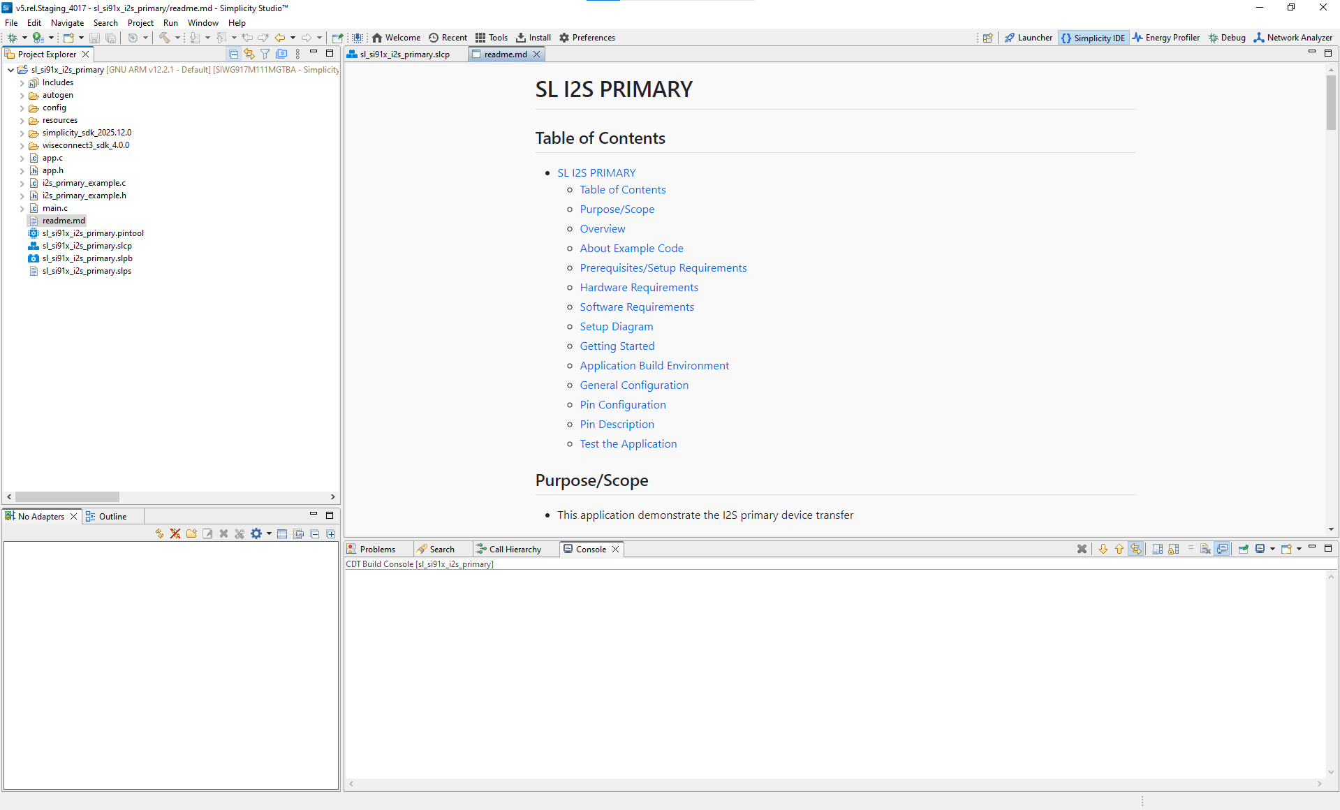
Typical Project Structure#
autogen/– Auto-generated configuration headers and linker scriptsconfig/– Platform-specific configuration headersresources/– Images and documentation assetssimplicity_sdk/– Gecko SDK platform and third-party librarieswiseconnect3_sdk_4.0.0/– WiSeConnect SDK components and resourcessl_si91x_i2s_primary.slcp– Project configuration filesl_si91x_i2s_primary.pintool– Pin Tool configuration for I²S pinsapp.c / app.h– Application source and header filesmain.c– Application entry pointreadme.md– Example documentation and usage instructions
Step 2. Add the I²S Component#
If your project does not already include I²S:
Open the project’s
.slcpfile.Go to the Software Components tab.
Search for I2S.
Add the required instances, for example:
I2S0for HP audioULP_I2Sfor low-power audio
To add more instances, select Add New Instance.
Simplicity Studio pulls in driver code and configuration automatically.
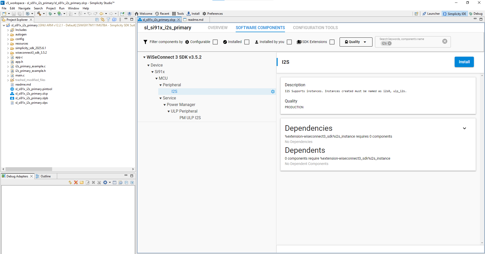
Figure: Adding the I²S component in Simplicity Studio
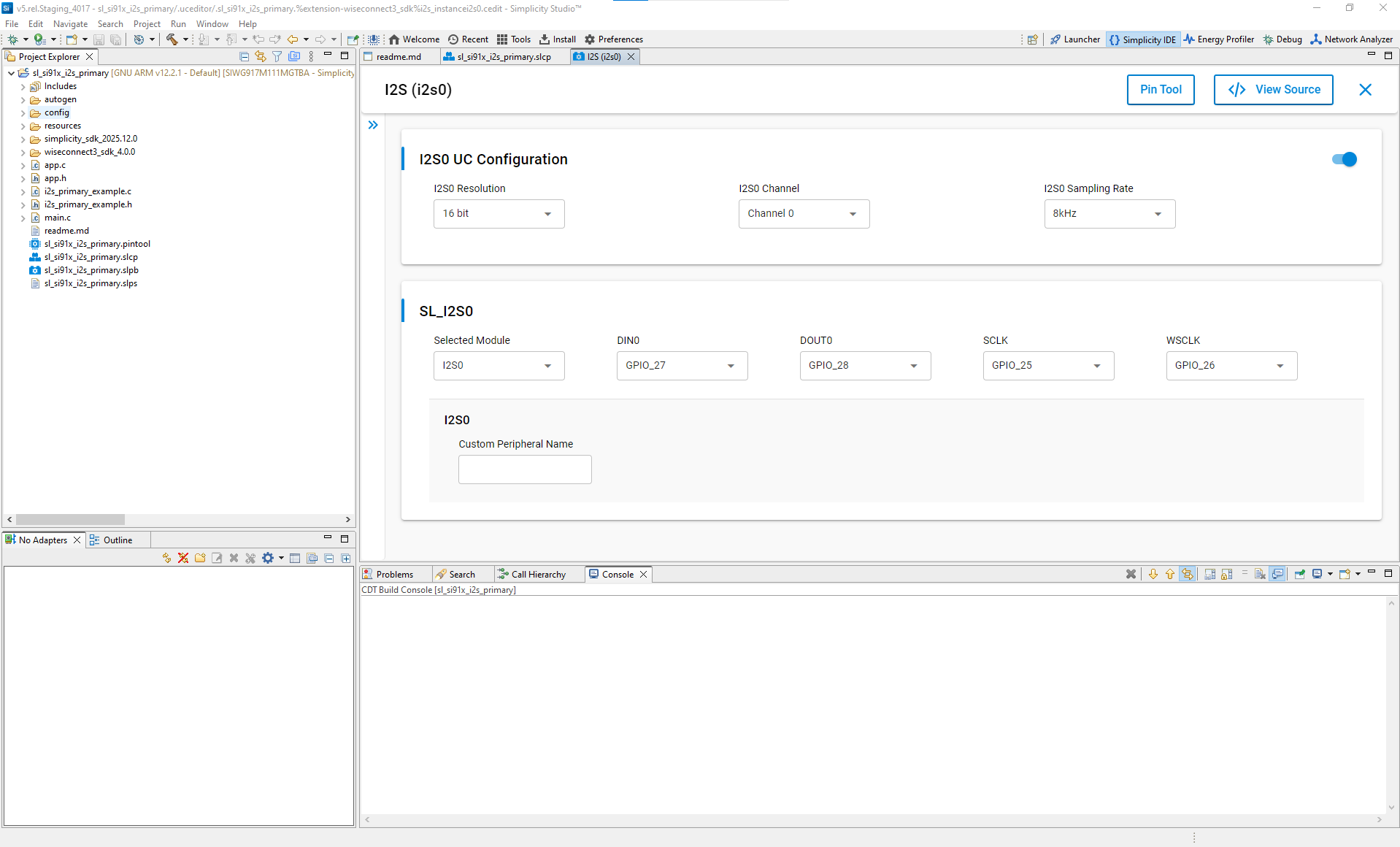
Step 3. Configure I²S with Universal Configurator (UC)#
In the Software Components view, select the I²S instance and click Install (if not already installed).
Click Configure to open Universal Configurator (UC).
Set the key parameters:
Parameter
Description
Options / Range
Resolution
Bits per audio sample
16, 24, or 32 bits
Channel
Channel instance
Channel 0, Channel 1
Sampling rate
Audio sample rate
8 kHz – 192 kHz
Selected module
I²S hardware instance
I2S0
DIN (data in)
Audio data input pin
GPIO_XX
DOUT (data out)
Audio data output pin
GPIO_XX
SCLK (bit clock)
Serial clock pin
GPIO_XX
WSCLK (word select / LR clock)
Left-right channel clock pin
GPIO_XX
Use the Pin Tool view to verify and adjust pin routing as needed.
Select pins from the drop-down list in UC.
Configure pin routing using the Pin Tool.
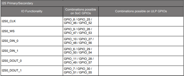
Figure: Recommended I²S pin selections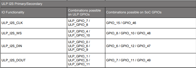
Figure: Recommended ULP I²S pin selectionsUC stores these settings in auto-generated configuration files under
autogen/.
Step 4. Configuration Parameters and Data Structures#
The I²S driver uses configuration structures and enums to describe operating mode, protocol, and transfer parameters.
Example Transfer Configuration#
typedef struct {
uint16_t mode; // Primary (controller) or Secondary (target) mode
uint16_t sync; // Synchronous or Asynchronous mode
uint16_t protocol; // Protocol (I²S or PCM)
uint16_t resolution; // Audio data resolution
uint32_t data_size; // Data word size (bits)
uint32_t sampling_rate; // Audio sampling rate (Hz)
uint32_t transfer_type; // Transfer type (Transmit or Receive)
} sl_i2s_xfer_config_t;Example Event Enumeration#
typedef enum {
SL_I2S_SEND_COMPLETE = ARM_SAI_EVENT_SEND_COMPLETE, // Send complete event
SL_I2S_RECEIVE_COMPLETE = ARM_SAI_EVENT_RECEIVE_COMPLETE, // Receive complete event
SL_I2S_TX_UNDERFLOW = ARM_SAI_EVENT_TX_UNDERFLOW, // DOUT underrun event
SL_I2S_RX_OVERFLOW = ARM_SAI_EVENT_RX_OVERFLOW, // DIN overflow event
SL_I2S_FRAME_ERROR = ARM_SAI_EVENT_FRAME_ERROR // Frame error event
} i2s_event_typedef_t;Power States and Modes#
typedef enum {
SL_I2S_POWER_OFF = ARM_POWER_OFF, // Power off mode
SL_I2S_FULL_POWER = ARM_POWER_FULL // Full power mode
} sl_i2s_power_state_t;
typedef enum {
SL_I2S_MASTER = ARM_SAI_MODE_MASTER, // I²S primary (controller) mode
SL_I2S_SLAVE = ARM_SAI_MODE_SLAVE // I²S secondary (target) mode
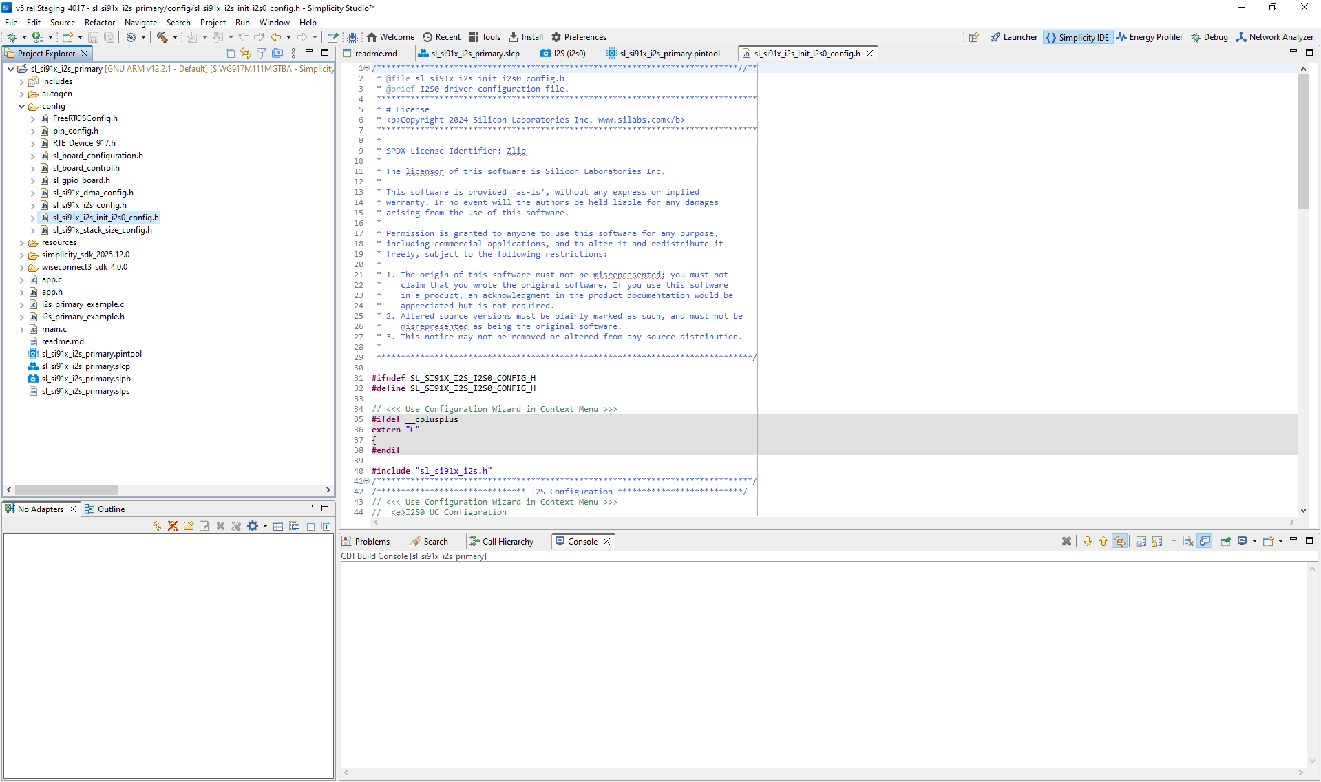
} sl_i2s_mode_t;Step 5. Autogenerated Initialization Code#
When you add or modify I²S components, Simplicity Studio automatically generates configuration and driver files.
In the UC interface, click View Source to inspect the generated code.
Step 6. Initialize I²S in Your Application#
Use WiSeConnect SDK APIs to initialize and configure I²S. The driver source and header files are located in:
/wiseconnect3_sdk_<version>/components/device/silabs/si91x/mcu/drivers/unified_api/inc/sl_si91x_i2s.h
/wiseconnect3_sdk_<version>/components/device/silabs/si91x/mcu/drivers/unified_api/src/sl_si91x_i2s.cExample Initialization Code#
status = sl_si91x_i2s_init(I2S_INSTANCE, &i2s_driver_handle);
if (status != SL_STATUS_OK) {
DEBUGOUT("I²S initialization failed. Error code: %u\r\n", status);
} else {
DEBUGOUT("I²S initialization successful.\r\n");
}
// Configure full power mode
status = sl_si91x_i2s_configure_power_mode(i2s_driver_handle, SL_I2S_FULL_POWER);
if (status != SL_STATUS_OK) {
DEBUGOUT("I²S power mode configuration failed.\r\n");
} else {
DEBUGOUT("I²S power mode configuration successful.\r\n");
}
// Register user callback
status = sl_si91x_i2s_register_event_callback(i2s_driver_handle, callback_event);
if (status != SL_STATUS_OK) {
DEBUGOUT("I²S callback registration failed.\r\n");
} else {
DEBUGOUT("I²S callback registration successful.\r\n");
}Step 7. Customize for Advanced Use Cases#
You can modify the generated configuration or initialization code to support advanced scenarios, such as:
User-defined callback handlers
Dynamic DMA channel allocation
Power-state-based reinitialization
For additional examples, see the I²S Usage Scenarios.
Step 8. Build, Flash, and Test#
After configuration, build and flash the firmware to your SiWx917 device. Use the VCOM console in Simplicity Studio or an external terminal application to monitor logs and verify I²S operation.
Step-by-Step: Build, Flash, and Test#
Build the project in Simplicity Studio.
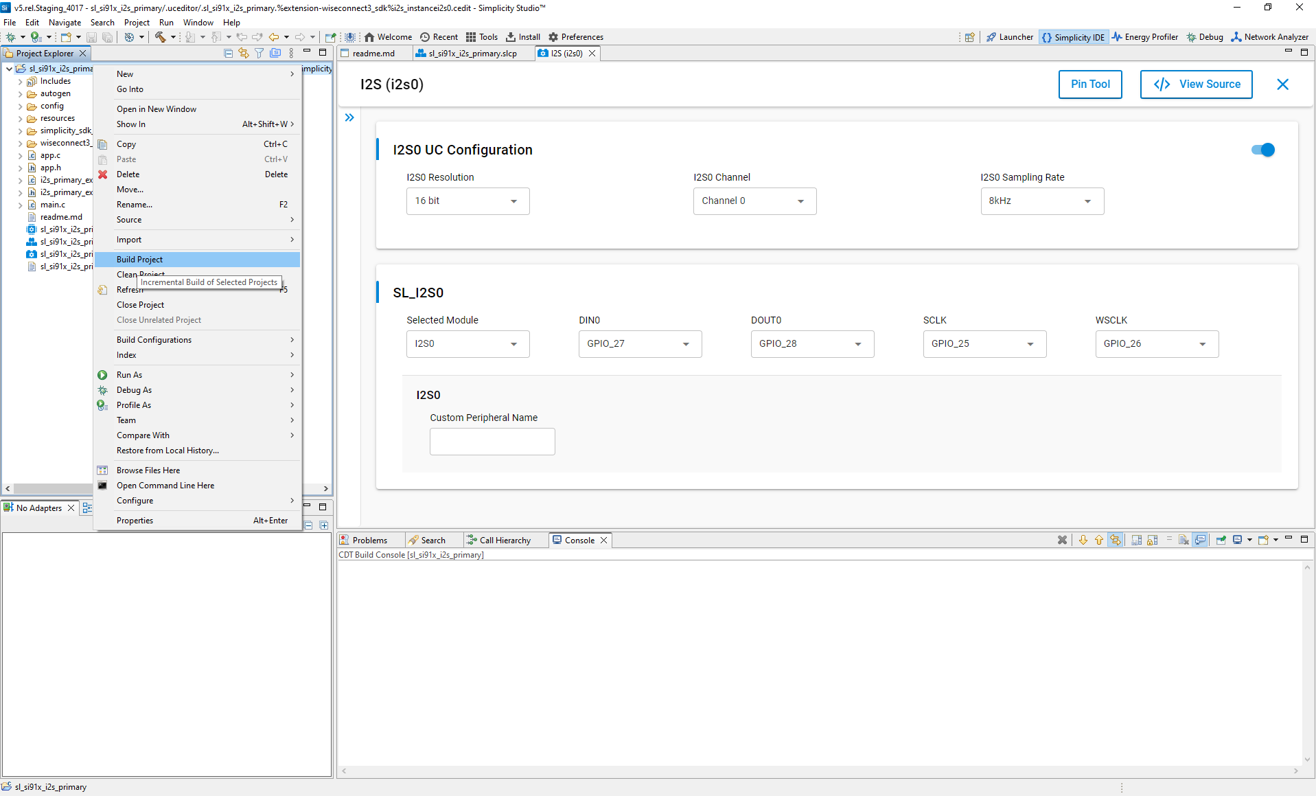
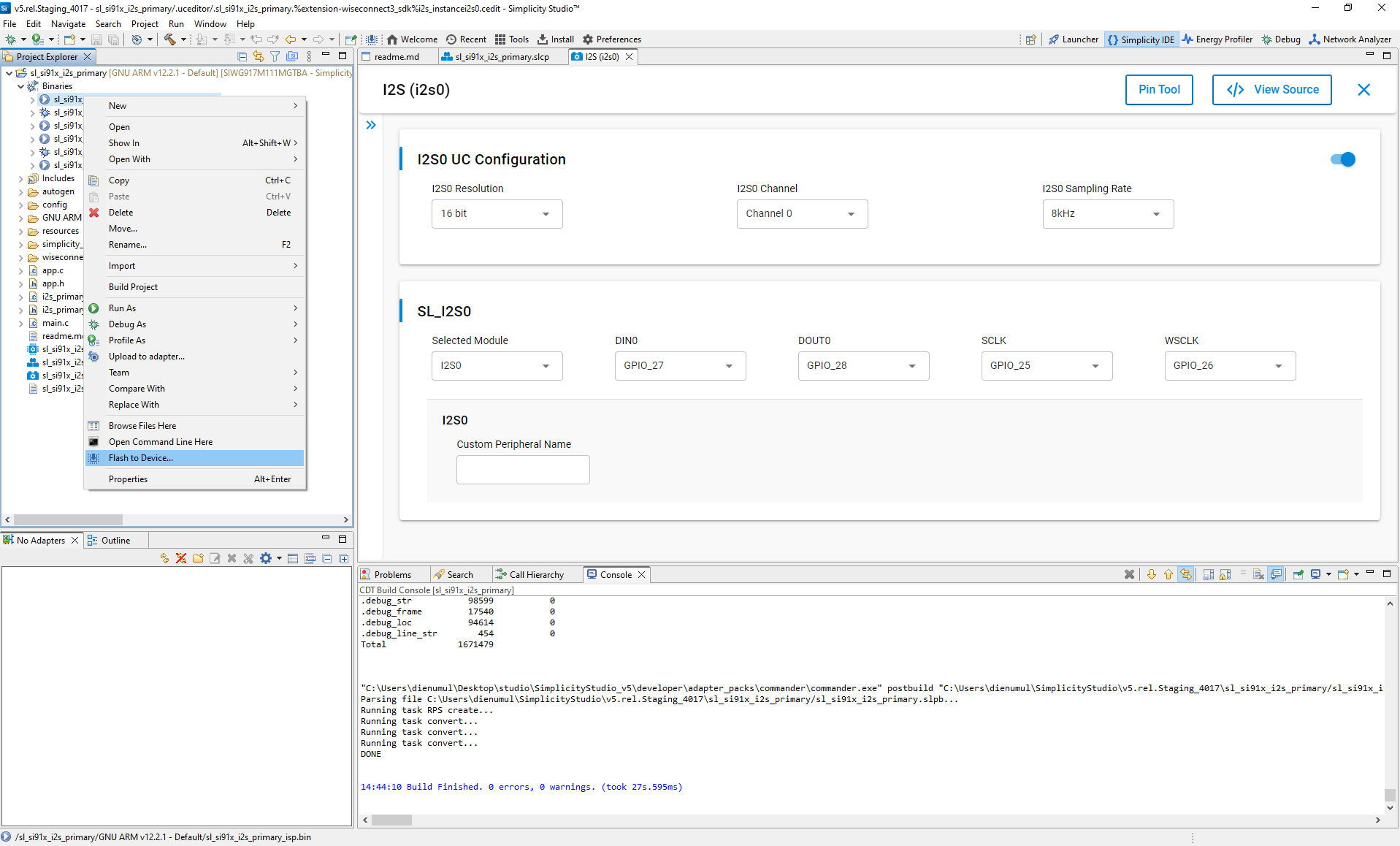
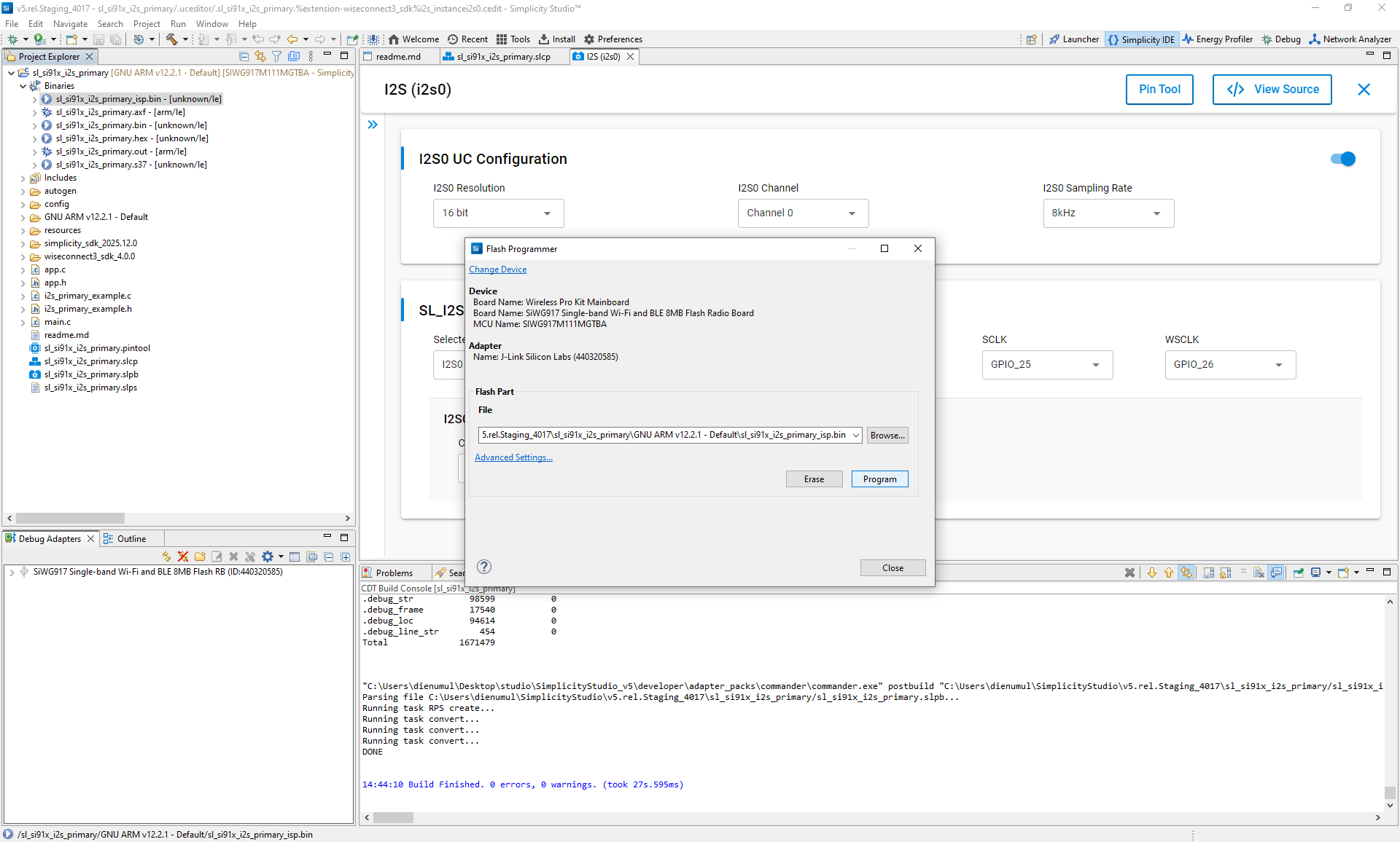
Flash the firmware to the SiWx917 device.
Verify I²S operation using the serial console or debugger.
Connected devices view:
Connect devices:
Launch console:
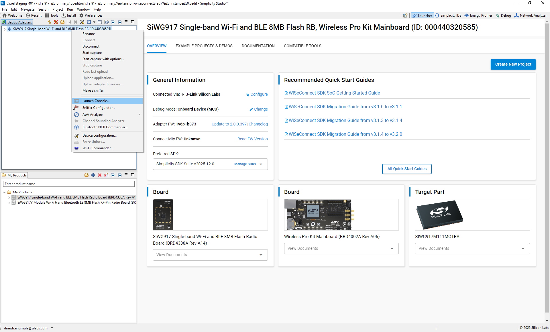
View console settings:
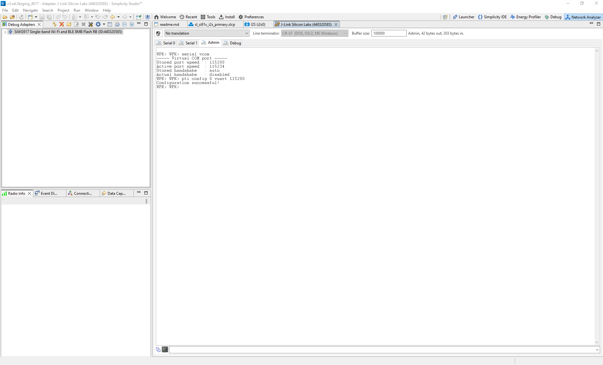
Console logs for Primary and Secondary:
How to view logs:
Open the console and select the
serial1tab.Place the cursor in the input field at the bottom.
Press Enter to activate the console.
Primary log example:
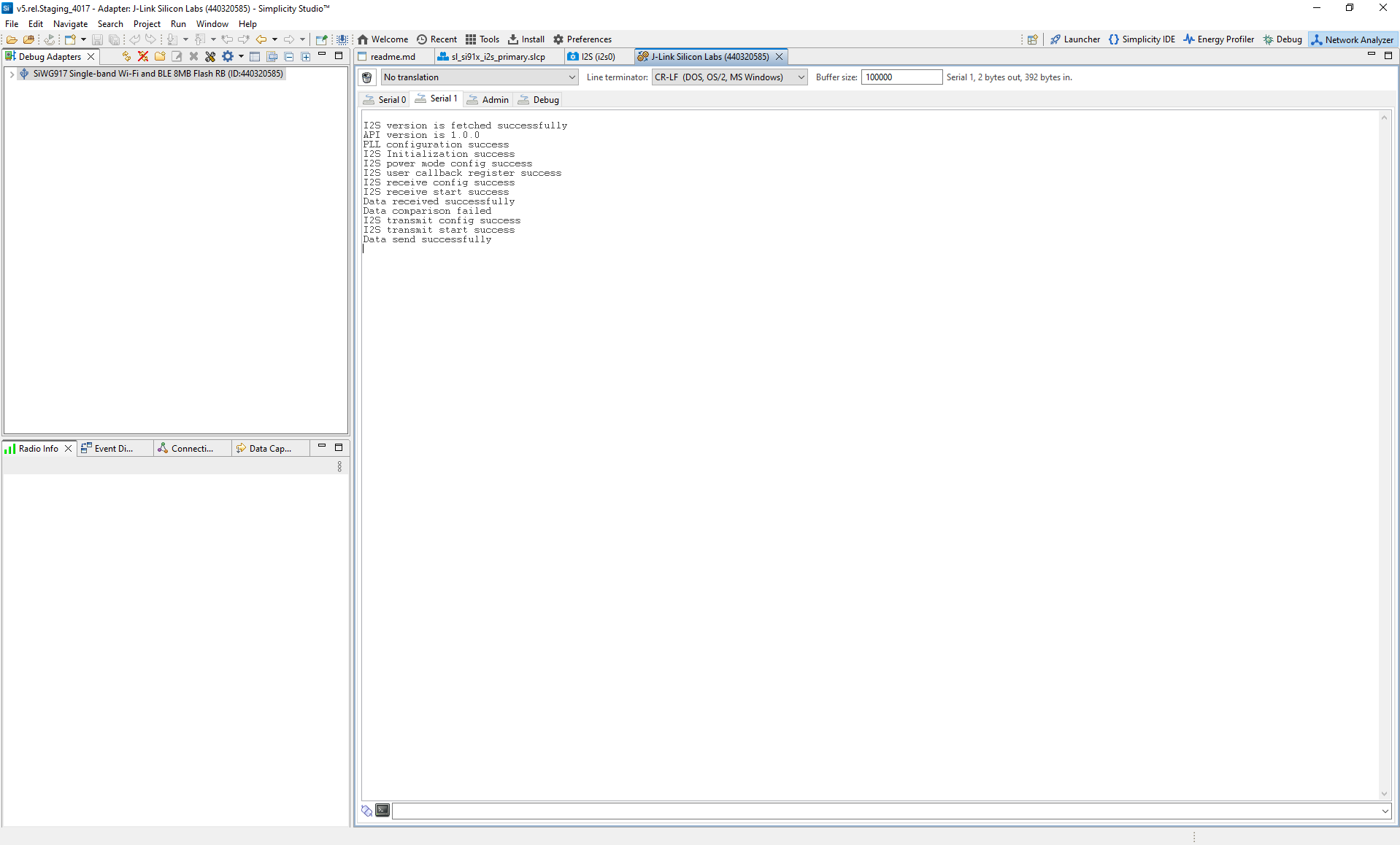
Secondary log example: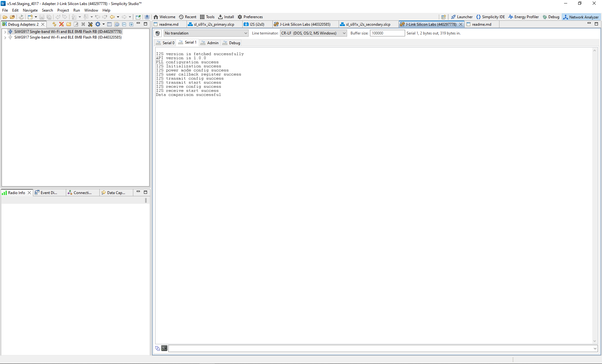
Note: You can also use terminal applications such as Tera Term or PuTTY instead of the Simplicity Studio VCOM console.
References#
Related Example Projects
WiSeConnect SDK I²S Peripheral Examples
SL Si91x – I2S Loopback
SL Si91x – I2S Primary
SL Si91x – I2S Secondary
SL Si91x – ULP I2S