Inter-Integrated Circuit (I²C) Initialization and Configuration#
The Silicon Labs WiSeConnect software development kit (SDK) provides a unified Inter-Integrated Circuit (I²C) driver application programming interface (API) for SiWx917 devices. It supports multiple I²C instances with configurable operating modes, transfer flows (blocking and non-blocking), and power management features.
This guide walks through the complete initialization and configuration process for I²C communication.
For broader SDK topics, see WiSeConnect documentation.
Startup Sequence#
Before using I²C, set up a project in Simplicity Studio and enable the I²C driver. In brief, you will:
Create or open a project.
Add the I²C component.
Configure instance, pins, speed, and addressing.
Generate the initialization code.
Build, flash, and test the result.
This section walks you through each step so you can bring up I²C quickly and verify the configuration on hardware.
Step-by-step I²C Initialization and Configuration in Simplicity Studio#
Step 1. Create or Open Your Project#
Launch Simplicity Studio.
Create a new project for your SiWx917 device, or open an existing one.
For a quick start, choose one of the I²C example projects from the WiSeConnect SDK.
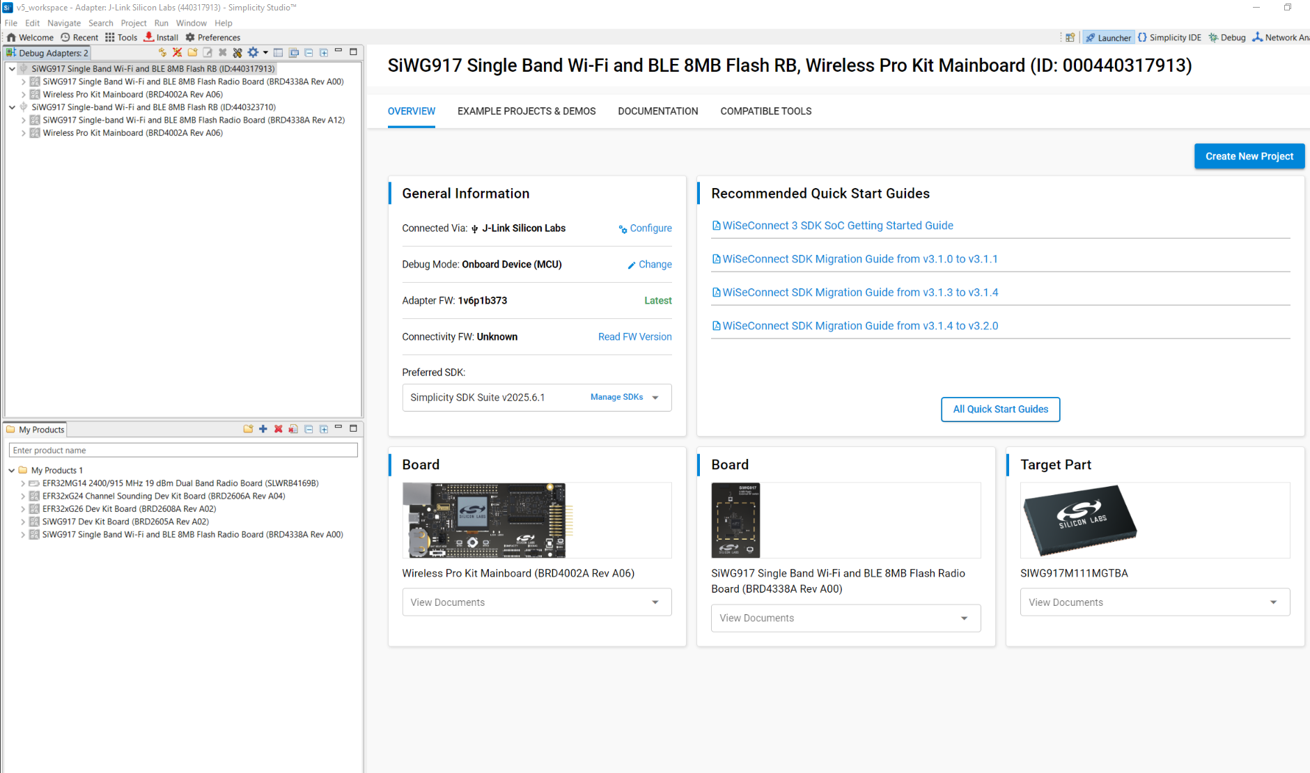
Connect your SiWx917 radio board; Studio will auto-detect it.
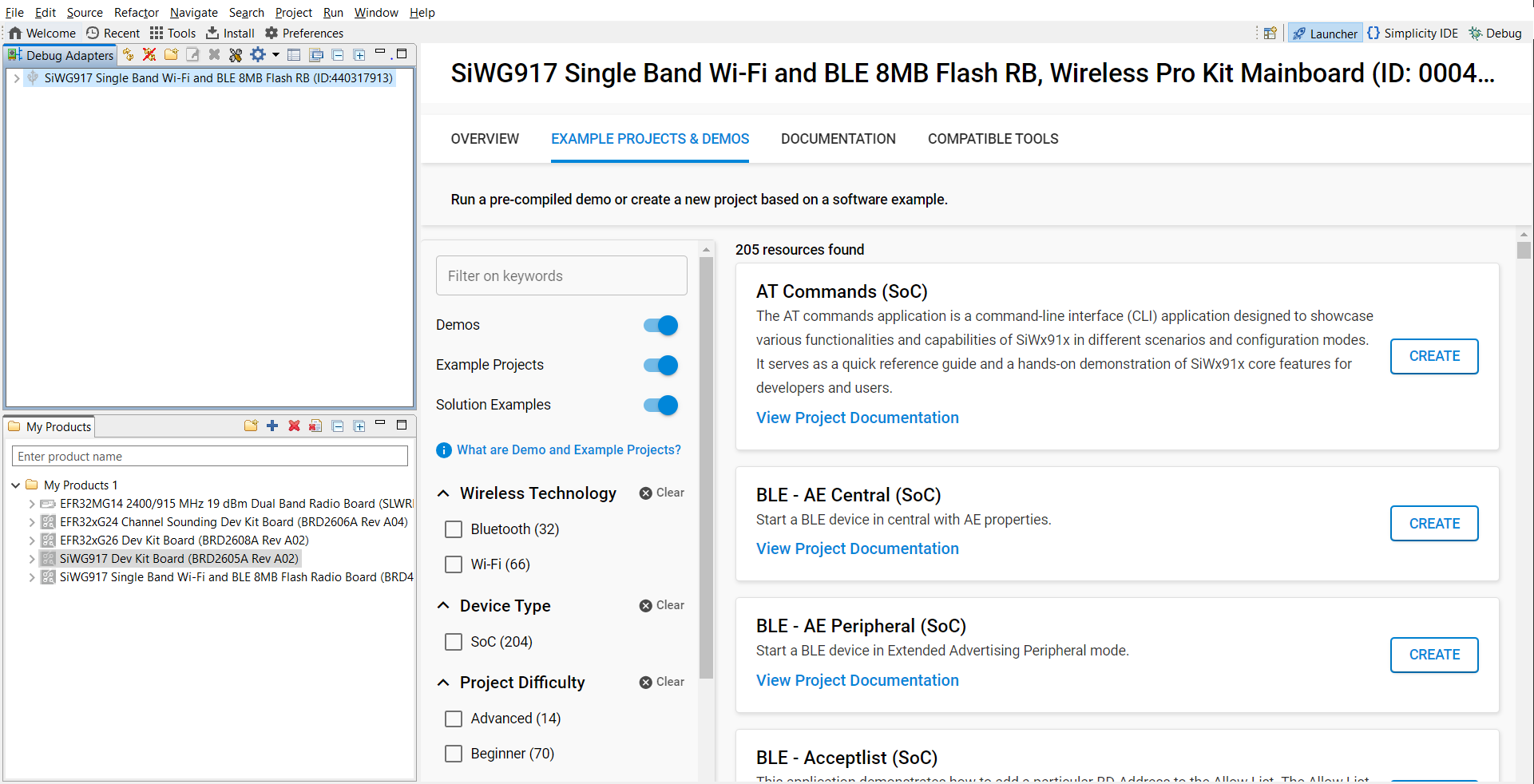
Figure: Board detection in Simplicity StudioIn Example Projects and Demos, search for
I2Cand open an example.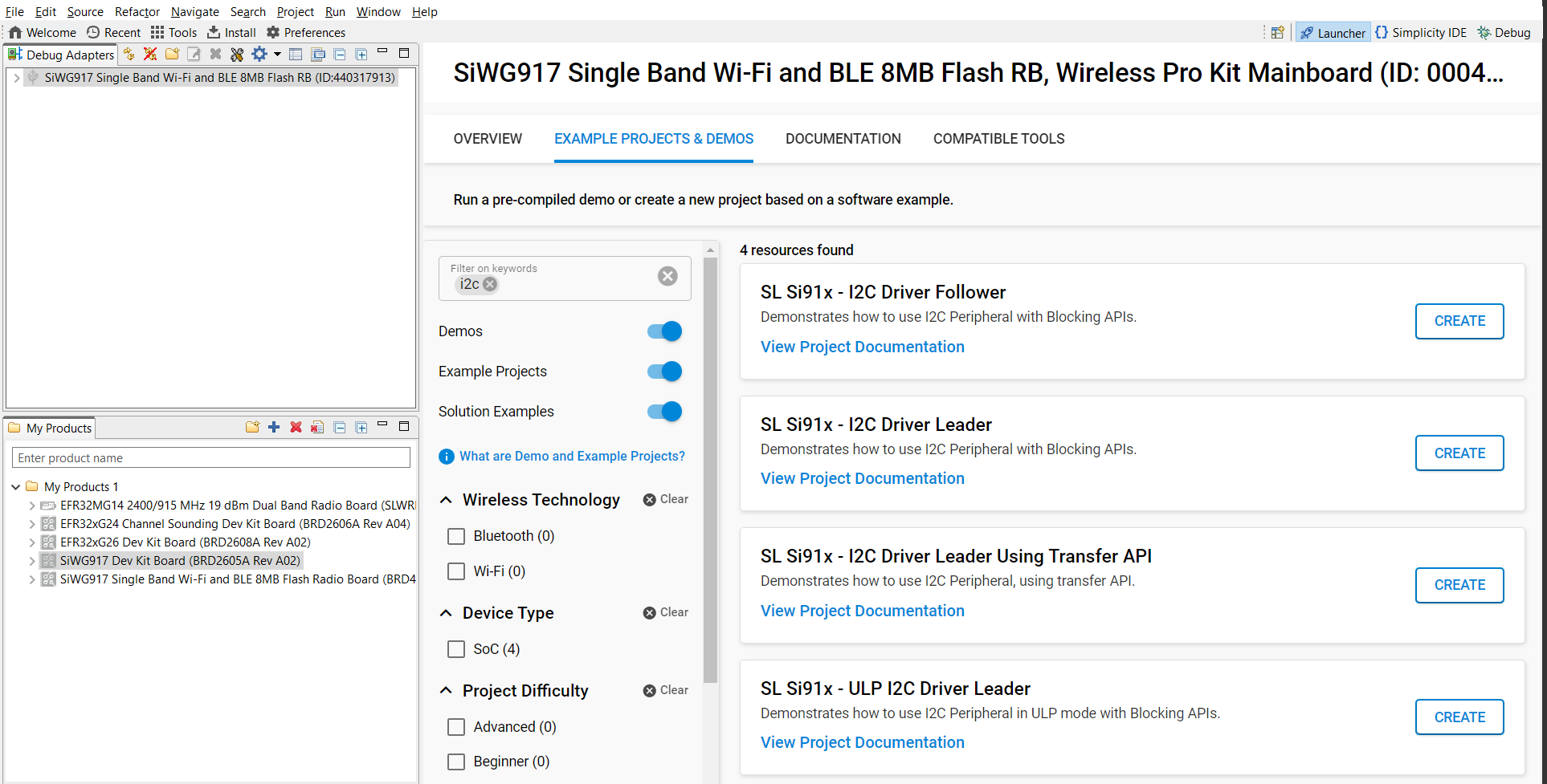
Figure: Searching for I²C example projectsClick Create to add the project to your workspace. Review the example’s documentation for usage details.
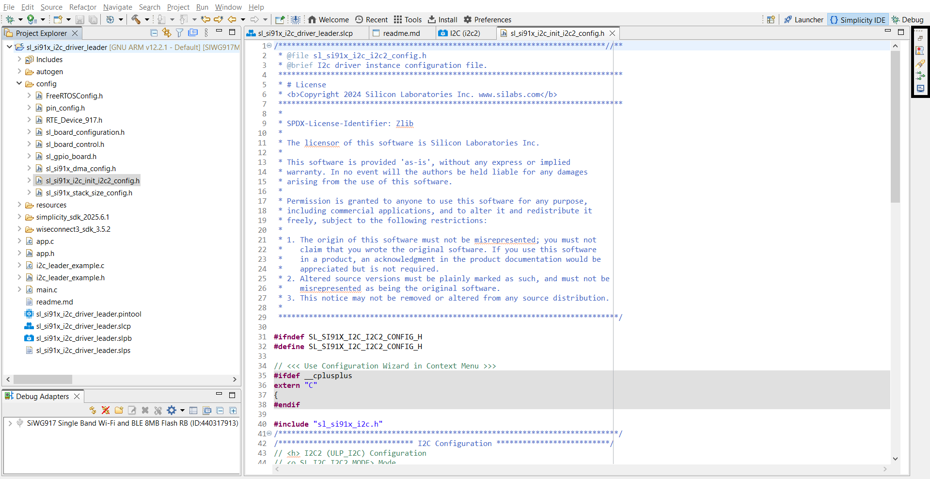
After you confirm project details (name, location, link/copy SDK sources), Studio generates the project. Most examples automatically open the
readme.md.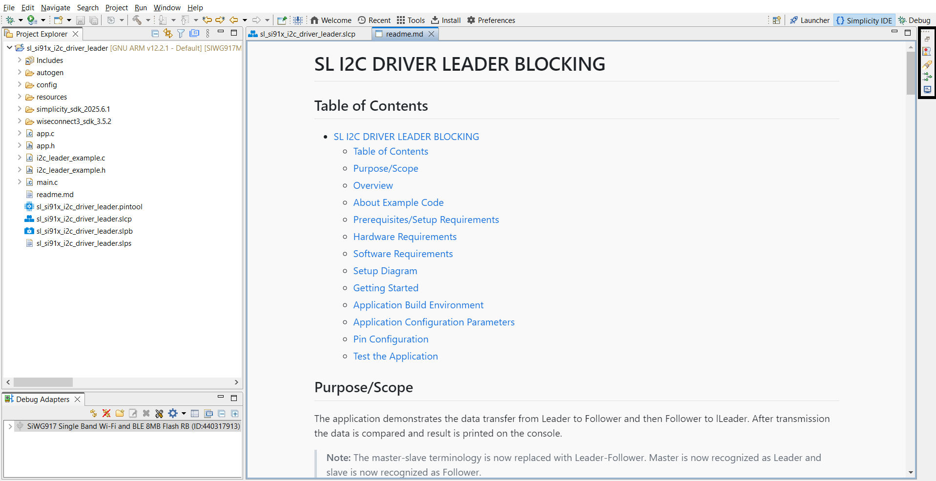
Typical project layout:
autogen/– Auto-generated files (configuration headers, linker scripts)config/– Platform-specific configuration headersresources/– Images and documentation assetssimplicity_sdk_/– Gecko SDK platform and third-party librariesplatform/– HAL, CMSIS-RTOS, and common librarieswiseconnect3_sdk_/– WiSeConnect SDK components and resourcesapp.c/app.h– Application sourcesi2c_leader_example.c/i2c_leader_example.h– I²C leader example sourcesmain.c– Application entry pointreadme.md– Example documentation and usagesl_si91x_i2c_driver_leader.slcp– Project configuration filesl_si91x_i2c_driver_leader.pintool– Pin configuration for I²C pinssl_si91x_i2c_driver_leader.slps– Project set file for managing related solutions
Step 2. Add the I²C Component#
In your project’s
.slcpconfiguration file, open the Software Components tab.Search for
I2Cand add the required peripheral (for example, I2C0, I2C1, ULP_I2C). To add other instances, click Add New Instance.
Step 3. Configure I²C with Universal Configurator (UC)#
Click Configure to set up the I²C instance.
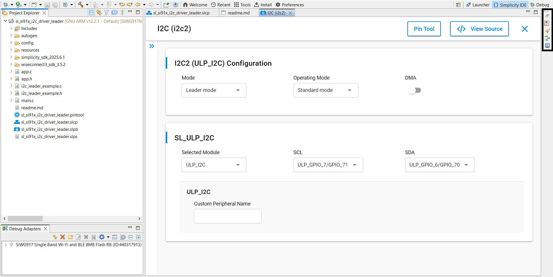
In the UC graphical interface, configure:
Mode: Leader or Follower.
Operating Speed: Standard, Fast, Fast Plus, or High Speed.
DMA (Direct Memory Access): Enable or disable.
Selected Module: Choose the module.
SCL/SDA: Select pins for the Serial Clock Line (SCL) and Serial Data Line (SDA).
Possible pin combinations:
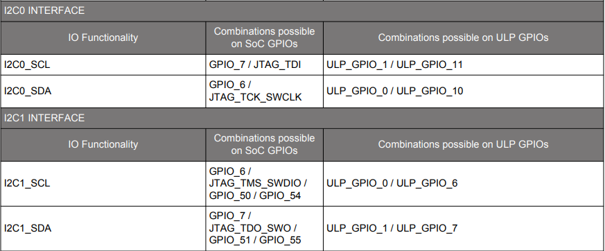
For I2C0 and I2C1:
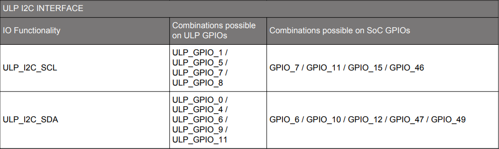
For ULP_I2C:
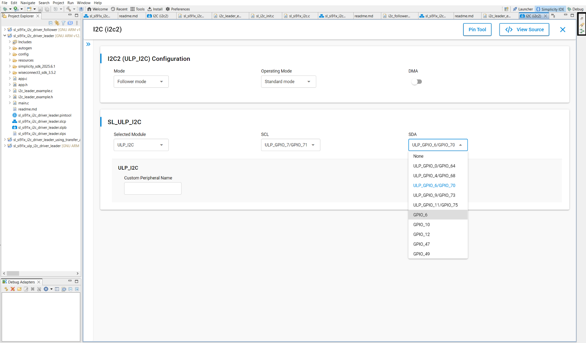
Pin selection methods in UC:
Select pins from a drop-down list:
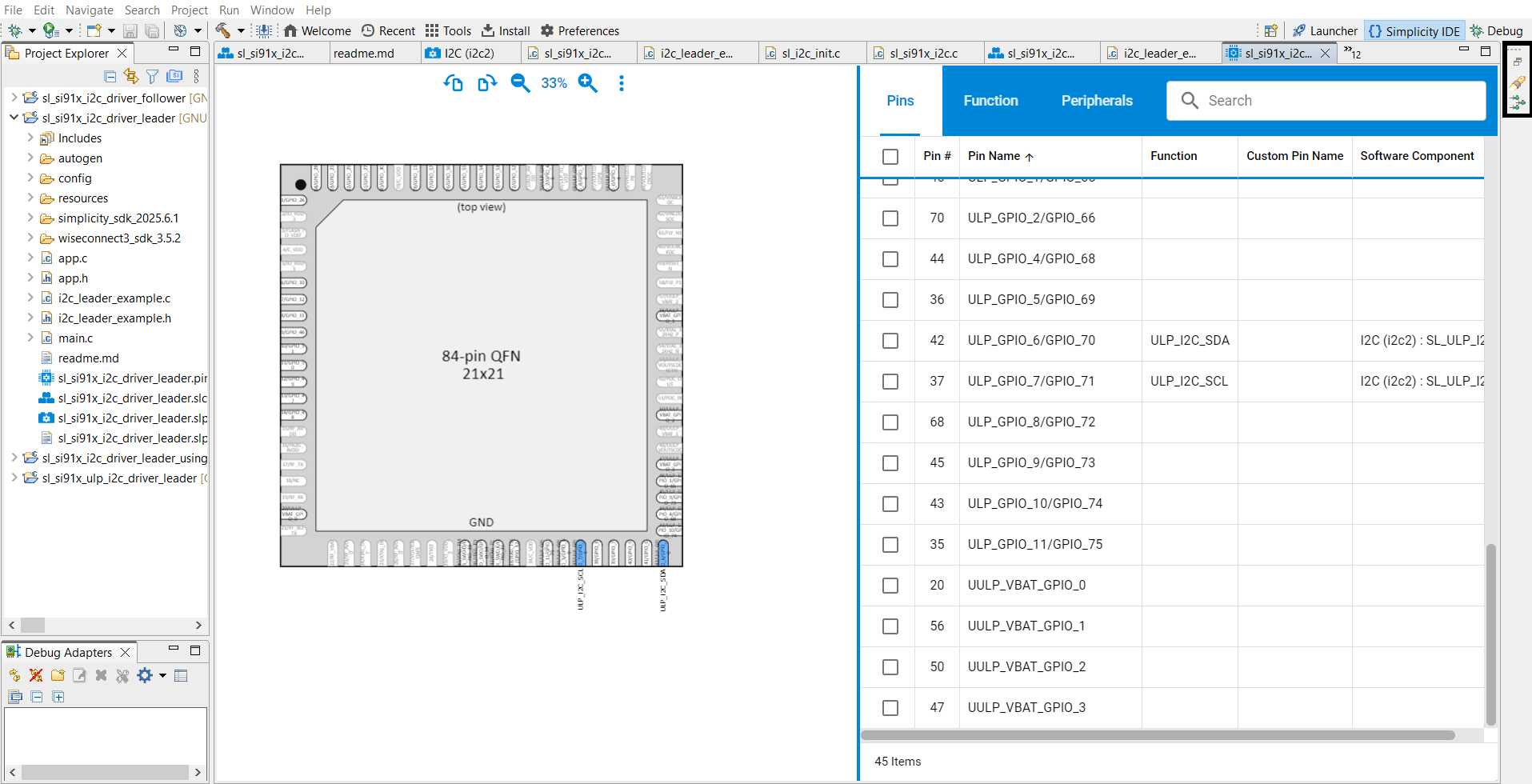
Select pins using the Pin Tool:
Configuration Parameters#
Configuration Structure#
typedef struct {
sl_i2c_mode_t mode; // Leader or Follower mode
sl_i2c_operating_mode_t operating_mode; // Speed configuration
sl_i2c_transfer_type_t transfer_type; // Interrupt or DMA
sl_i2c_callback_t i2c_callback; // Callback function pointer
} sl_i2c_config_t;Operating Modes#
typedef enum {
SL_I2C_STANDARD_MODE = 1, // 100 kHz
SL_I2C_FAST_MODE = 2, // 400 kHz
SL_I2C_FAST_PLUS_MODE = 3, // 1 MHz
SL_I2C_HIGH_SPEED_MODE = 4 // 3.4 MHz
} sl_i2c_operating_mode_t;Transfer Types#
typedef enum {
SL_I2C_USING_INTERRUPT = 0, // Blocking transfer
SL_I2C_USING_DMA = 1 // Non-blocking DMA transfer
} sl_i2c_transfer_type_t;I²C Modes#
typedef enum {
SL_I2C_LEADER_MODE = 0, // Leader (Master) mode
SL_I2C_FOLLOWER_MODE = 1 // Follower (Slave) mode
} sl_i2c_mode_t;Step 4. Generate Initialization Code#
When you add or modify I²C components, Simplicity Studio automatically adds the driver and configuration files.
Click View Source in the UC configuration UI to view the generated configuration files.
Step 5. Initialize I²C in Your Application#
Use WiSeConnect SDK APIs to initialize I²C. Driver source and header files are located at:
/wiseconnect3_sdk_<version>/components/device/silabs/si91x/mcu/drivers/unified_api/inc/sl_si91x_i2c.h /wiseconnect3_sdk_<version>/components/device/silabs/si91x/mcu/drivers/unified_api/src/sl_si91x_i2c.cThe I²C configuration structure is auto-generated in the
autogenfolder.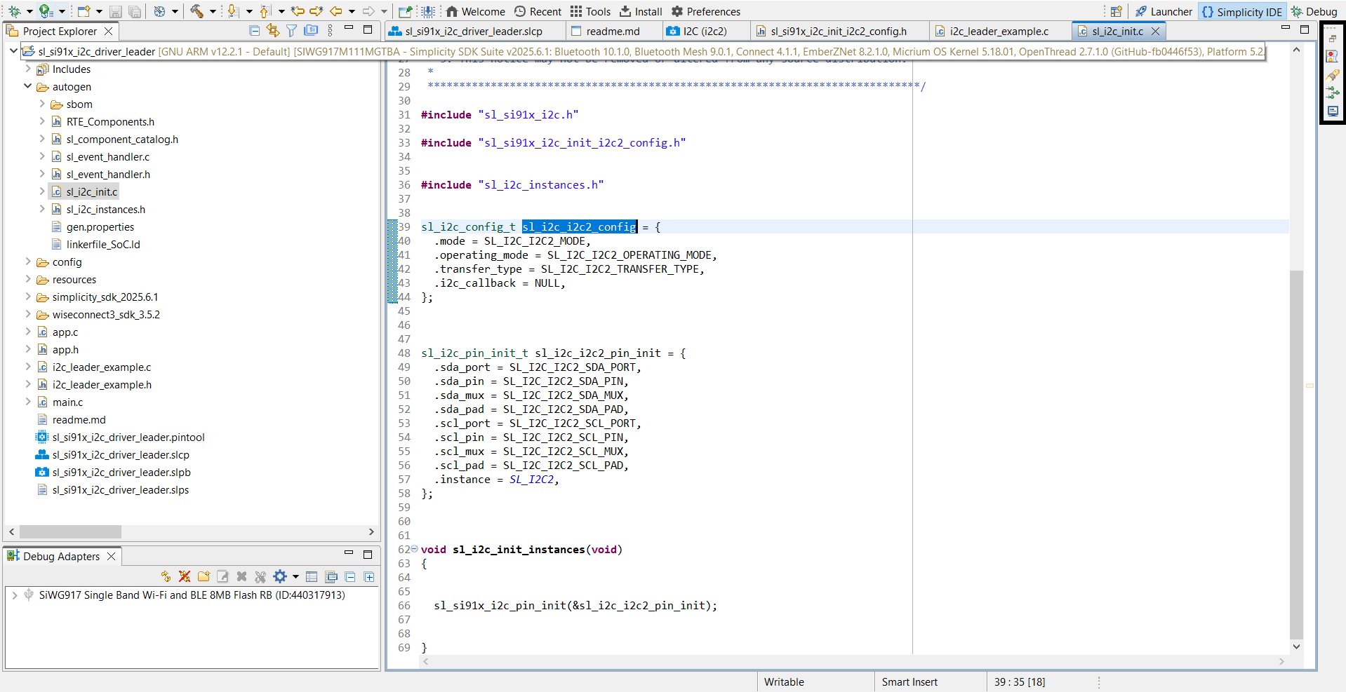
Example initialization code:
// Initializing I2C instance
i2c_status = sl_i2c_driver_init(i2c_instance, &sl_i2c_config);
DEBUGINIT();
if (i2c_status != SL_I2C_SUCCESS) {
DEBUGOUT("sl_i2c_driver_init : Invalid Parameters, Error Code : %u \n", i2c_status);
} else {
DEBUGOUT("Successfully initialized and configured I2C leader\n");
}
// Configuring RX and TX FIFO thresholds
i2c_status = sl_i2c_driver_configure_fifo_threshold(i2c_instance, I2C_TX_FIFO_THRESHOLD, I2C_RX_FIFO_THRESHOLD);
if (i2c_status != SL_I2C_SUCCESS) {
DEBUGOUT("sl_i2c_driver_configure_fifo_threshold : Invalid Parameters, Error Code : %u \n", i2c_status);
} else {
DEBUGOUT("Successfully configured I2C TX and RX FIFO thresholds\n");
}
// Enabling combined format transfer by enabling repeated start
i2c_status = sl_i2c_driver_enable_repeated_start(i2c_instance, true);
if (i2c_status != SL_I2C_SUCCESS) {
DEBUGOUT("sl_i2c_driver_enable_repeated_start : Invalid Parameters, Error Code : %u \n", i2c_status);
} else {
DEBUGOUT("Successfully enabled repeated start\n");
}Step 6. Set Follower Address (if needed)#
For follower mode, set the device address using the appropriate API.
// Configuring follower mask address
i2c_status = sl_i2c_driver_set_follower_address(i2c_instance, OWN_I2C_ADDR);
if (i2c_status != SL_I2C_SUCCESS) {
DEBUGOUT("sl_i2c_driver_init : Invalid Parameters, Error Code : %u \n", i2c_status);
} else {
DEBUGOUT("Successfully configured I2C follower address\n");
}Step 7. Customize for Advanced Use Cases#
Modify the generated configuration or initialization code for custom requirements (for example, callback functions or advanced DMA settings).
For more use cases, see I²C Usage Scenarios.
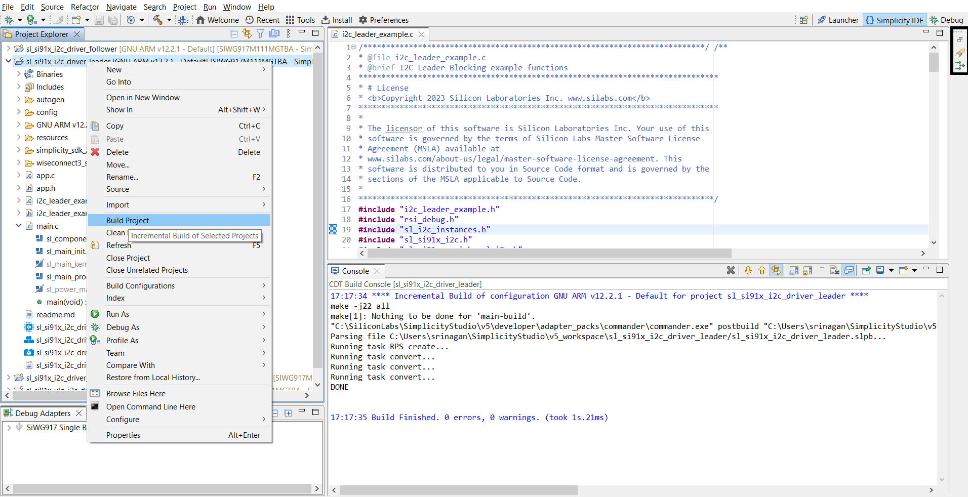
Step 8. Build, Flash, and Test#
After configuration, build the project, flash the firmware to the device, and test I²C operation. Simplicity Studio provides a built-in Virtual COM (VCOM) console for viewing logs.
Step-by-step: Build, Flash, and Test#
Build your project in Simplicity Studio.
Flash the firmware to the SiWx917 device.
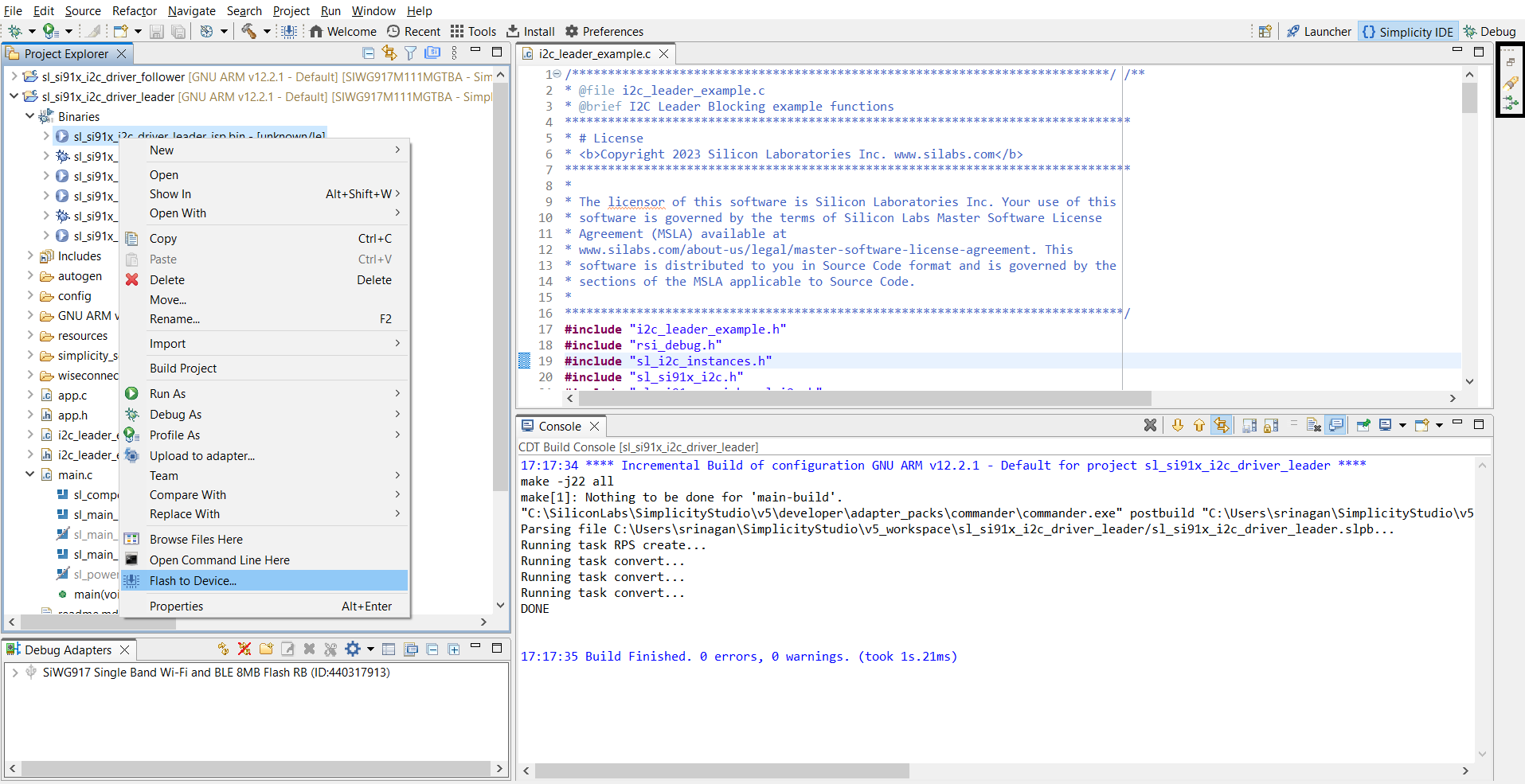
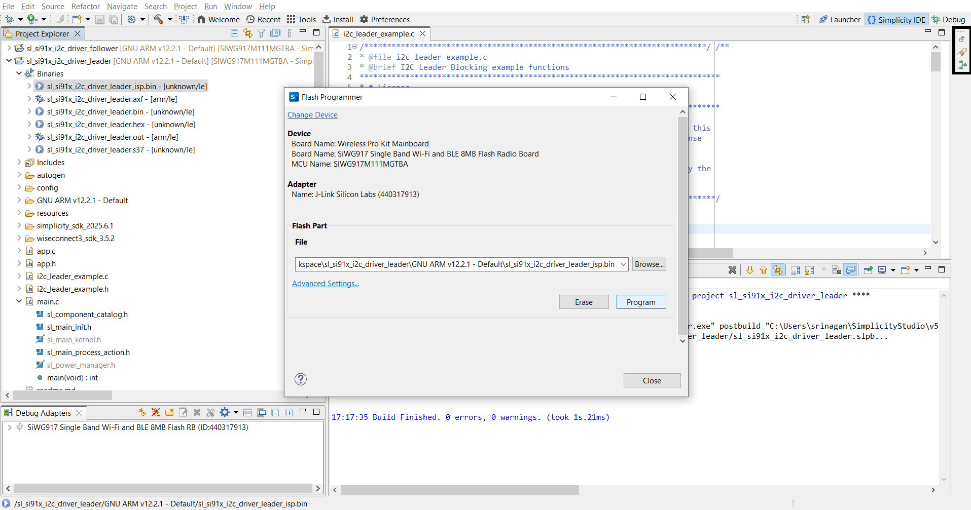
Verify I²C operation using the serial console or debugger.
Simplicity Studio provides a built-in VCOM console to view logs.
Connected devices view:
Connect devices:
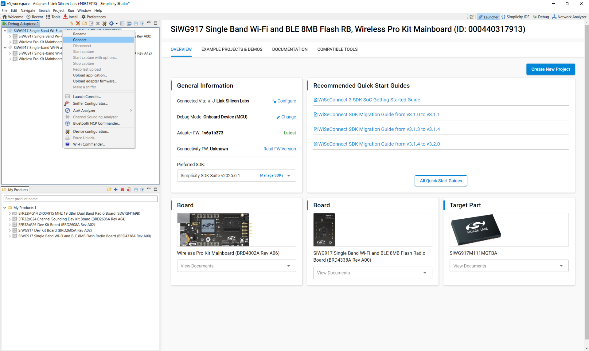
Launch console:
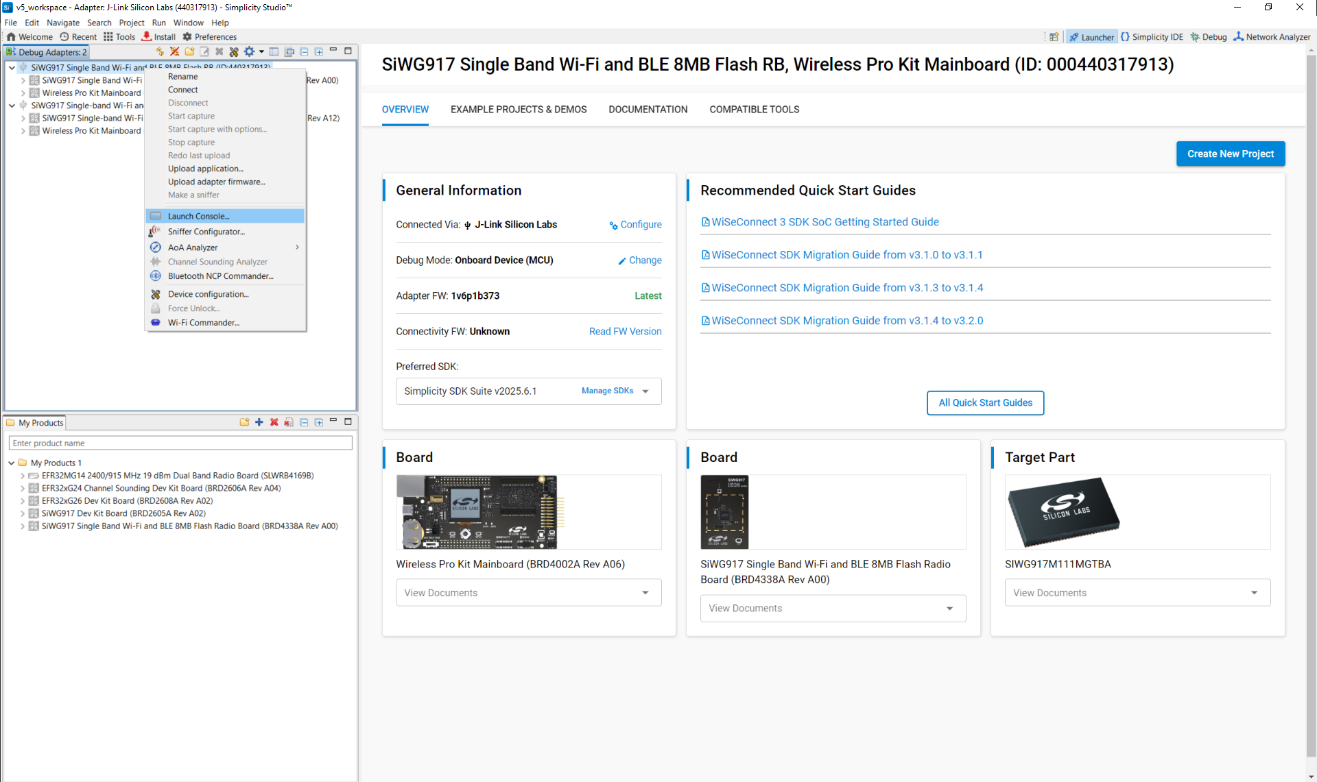
View current launch settings:
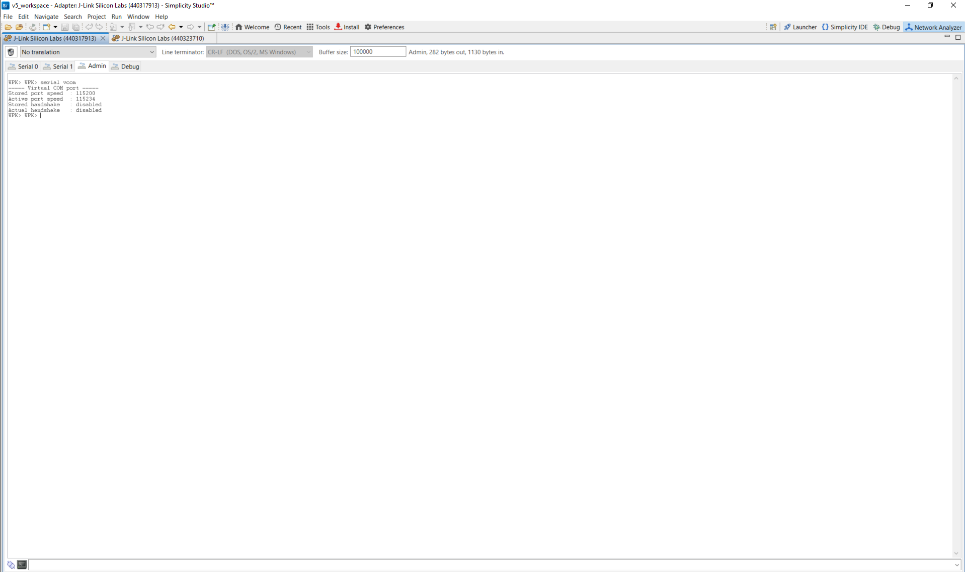
How to view logs:
Open the console and select the serial1 tab.
Place the cursor in the text entry field at the bottom.
Press Enter to activate the console.
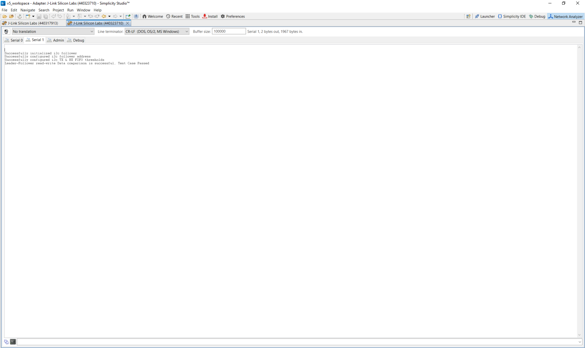
Follower log example:
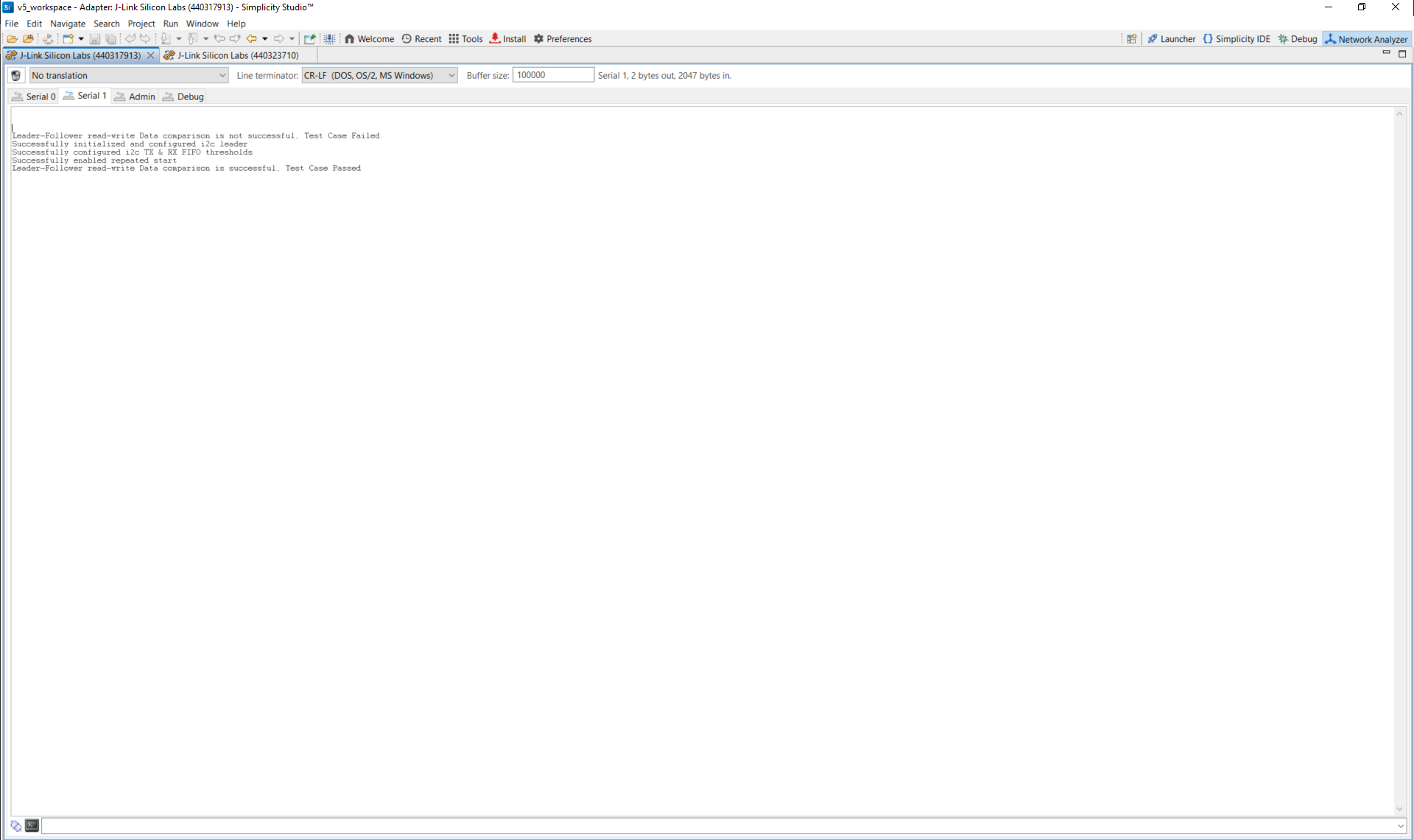
Leader log example:
Note: You can also use terminal programs such as Tera Term or PuTTY instead of the VCOM console.
References#
Related Example Projects
WiSeConnect SDK I2C Peripheral Examples
SL Si91x – I2C Driver Follower
SL Si91x – I2C Driver Leader
SL Si91x – I2C Driver Leader Using Transfer API
SL Si91x – ULP I2C Leader