Pulse Code Modulation (PCM) Initialization and Configuration#
This section explains how to initialize and configure the Pulse Code Modulation (PCM) peripheral on SiWx917 devices using Simplicity Studio, the WiSeConnect software development kit (SDK), and the Universal Configurator (UC).
You will learn how to:
Create a PCM-enabled project
Add and configure PCM components
Set sample rate, bit depth, and clocking modes
Assign pins for FSYNC, BCLK, DIN, and DOUT
Initialize PCM in code and validate transfers using blocking or DMA modes
PCM operates in the high-performance (HP) domain and is intended for synchronous, low-latency audio applications such as voice paths, telephony interfaces, or external DSP communication.
Step 1. Create or Open a Project#
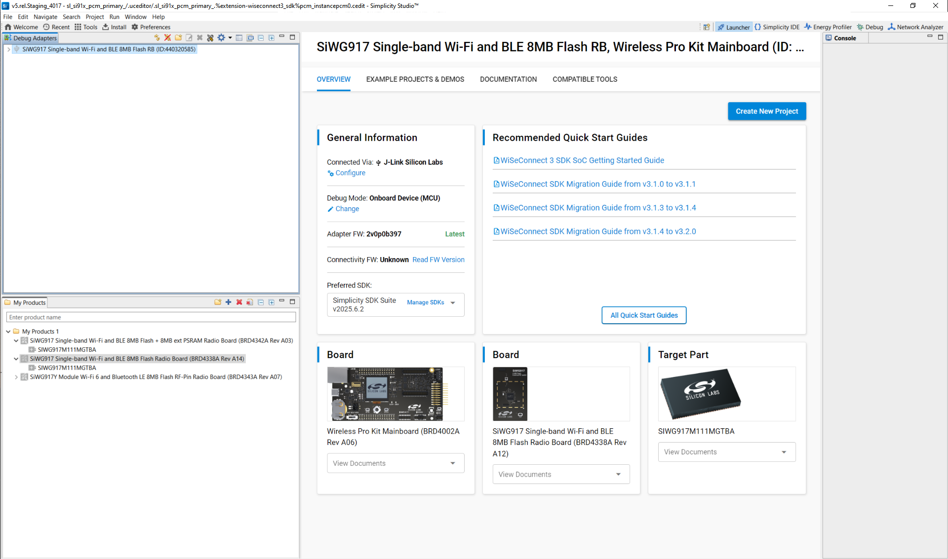
Launch Simplicity Studio and connect a supported SiWx917 evaluation board.
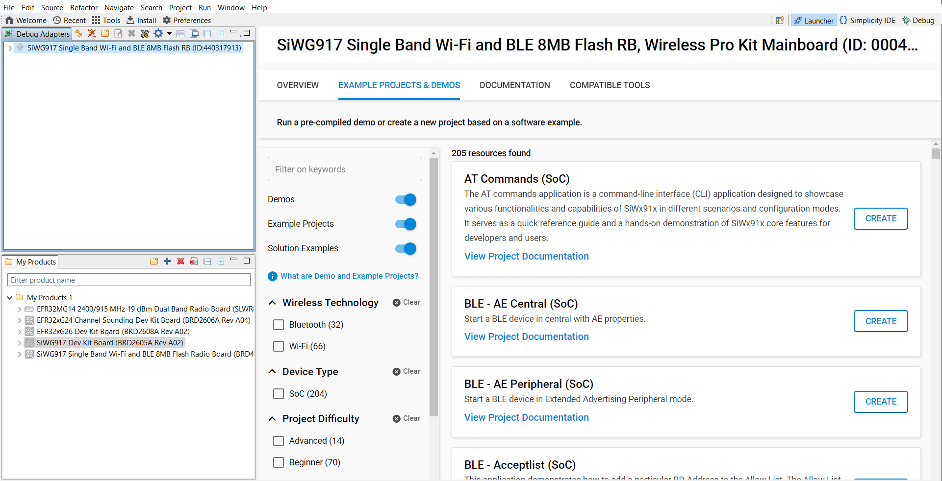
Figure: Board detection in Simplicity StudioCreate a new project or open an existing one based on one of the following WiSeConnect PCM examples:
sl_si91x_pcm_primarysl_si91x_pcm_secondarysl_si91x_pcm_loopback
Select an example and click Create to import it.
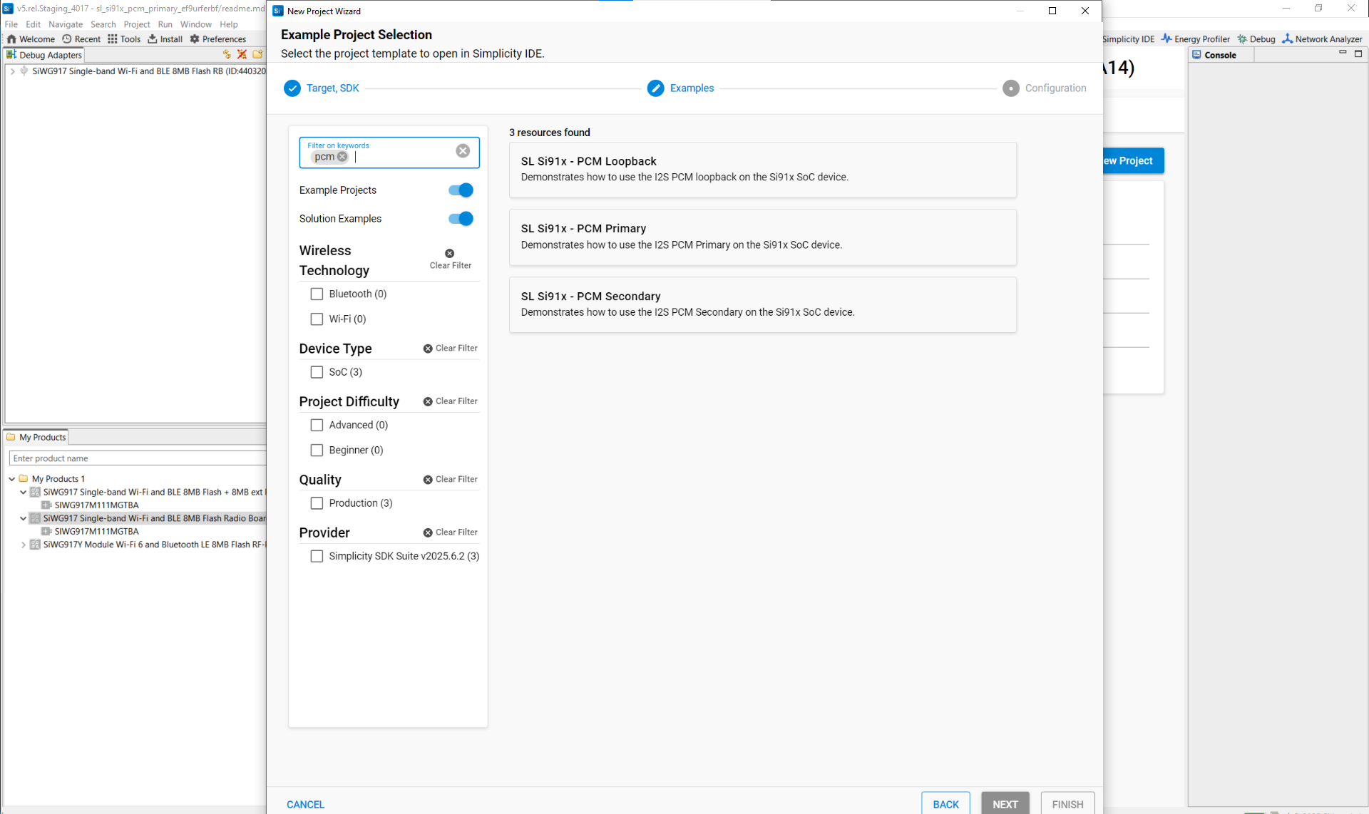
Figure: Search example PCM projectsReview the included
readme.mdfor wiring and board-specific notes.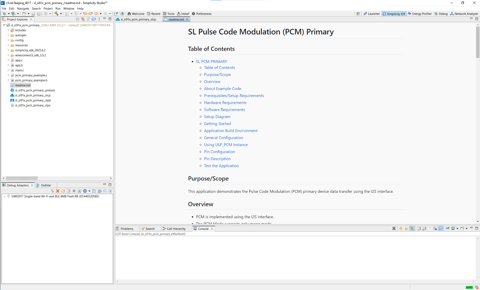
Typical directory structure
autogen/– Auto-generated files (configuration headers, linker scripts)config/– Platform-specific configuration headersresources/– Images and documentation assetssimplicity_sdk/– Gecko SDK platform and third-party librariesplatform/– HAL, CMSIS-RTOS, and common libraries
wiseconnect3_sdk_4.0.0/– WiSeConnect SDK components and resourcescomponents/– Wi-Fi, BLE, Si91x MCU subsystem
sl_si91x_pcm_primary.slcp– Project configuration filesl_si91x_pcm_primary.slps– Project set filesl_si91x_pcm_primary.pintool– Pin configuration for PCM pinsapp.c,app.h,main.c– Application sourcesreadme.md– Example documentation and usage
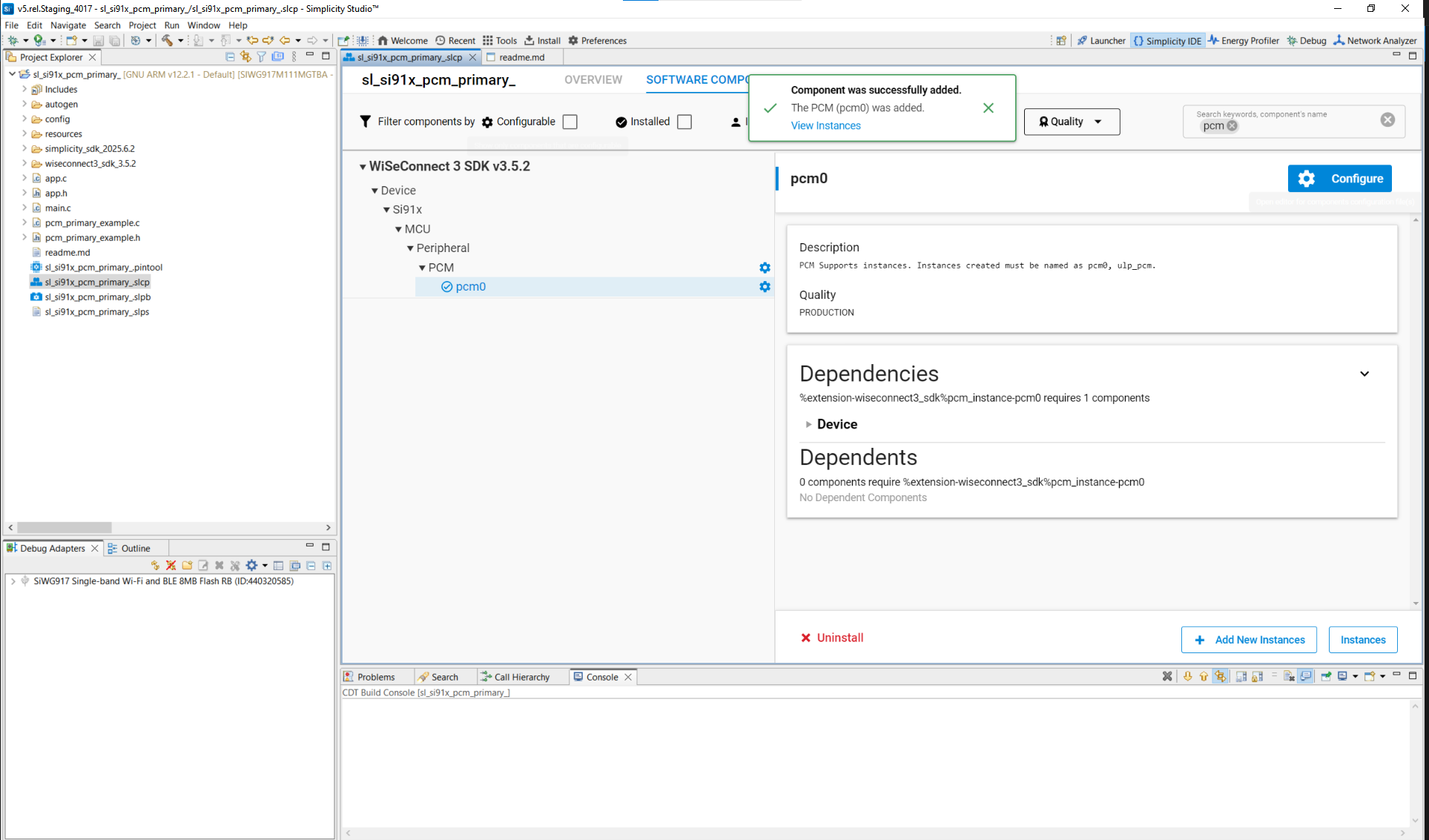
Step 2. Add the PCM Component#
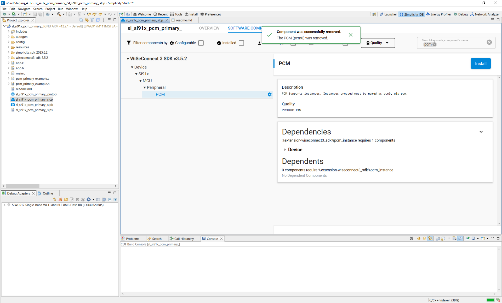
Open the project’s
.slcpfile.Select Software Components.
Search for PCM, or navigate to WiSeConnect SDK → Device → Si91x → MCU → Peripherals → PCM.
Install the PCM component.
To add more instances, click Add New Instance (for example,
PCM0).
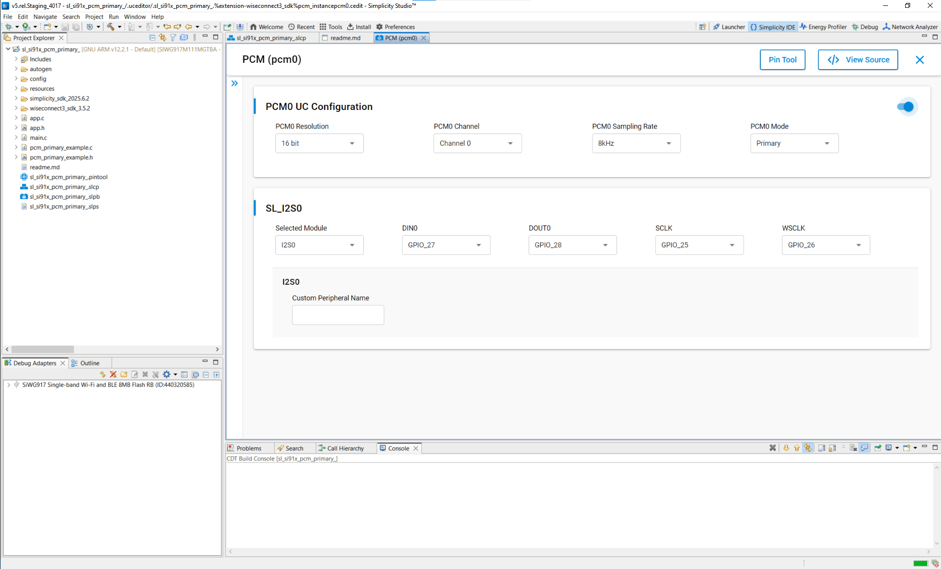
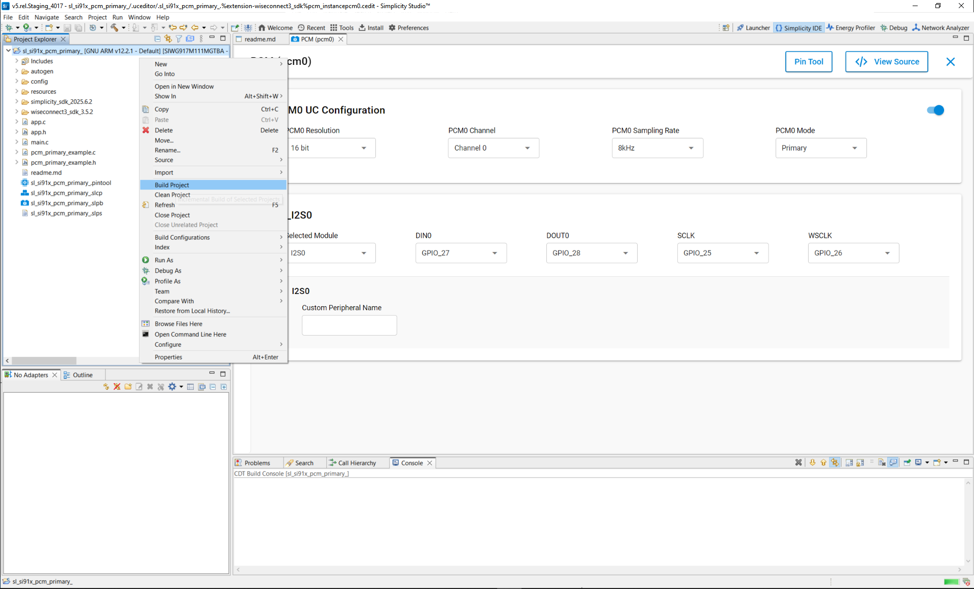
Step 3. Configure PCM with Universal Configurator (UC)#
Click Install, then Configure to set up the PCM instance.
UC Parameters#
Parameter | Description | Options / Range |
|---|---|---|
PCM resolution | Bits per audio sample | 16, 24, 32 |
PCM sampling rate | Audio sample rate (kHz) | 8, 11.025, 16, 22.05, 24 |
Selected module | PCM hardware instance | PCM0 |
DIN0 | Data input pin | GPIO_XX (selectable) |
DOUT0 | Data output pin | GPIO_XX (selectable) |
BCLK | Bit clock pin | GPIO_XX (selectable) |
FSYNC | Frame-sync pin | GPIO_XX (selectable) |
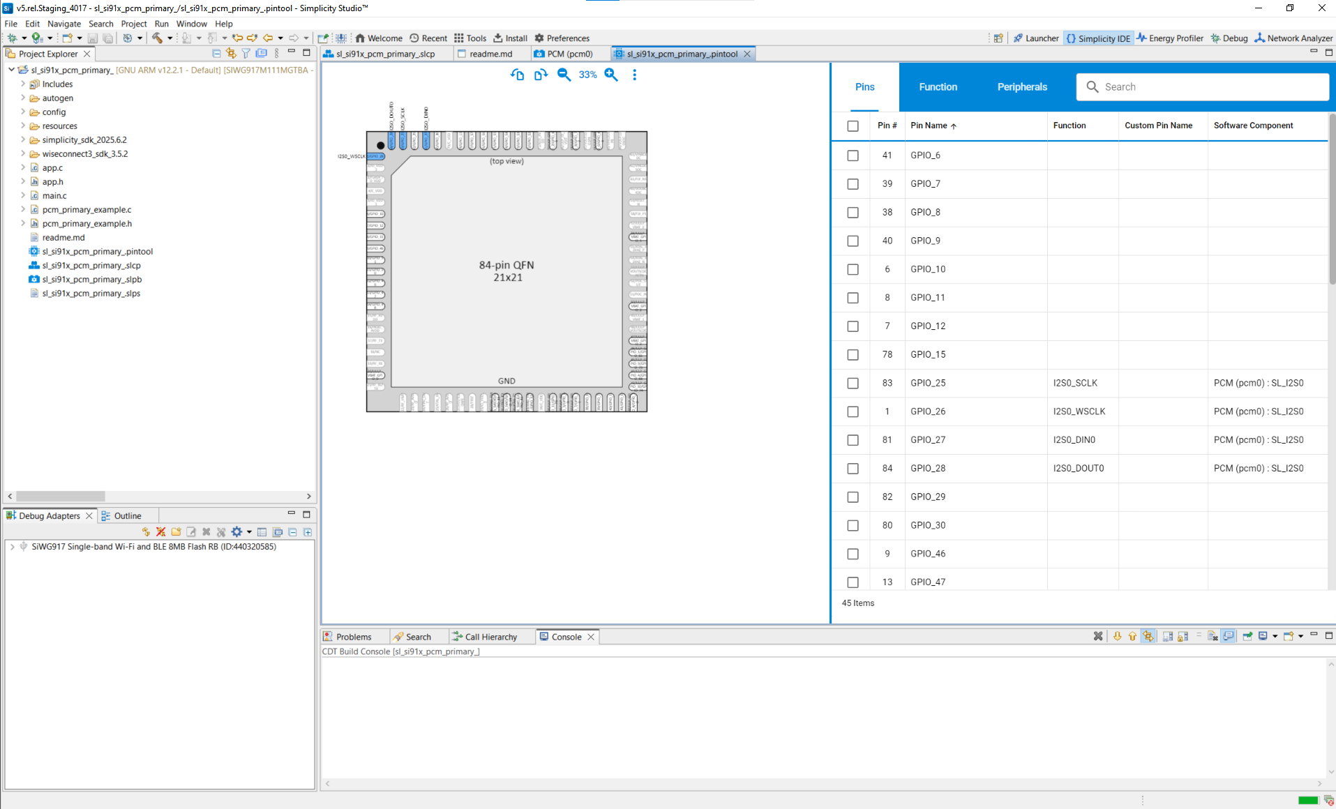
Pin selection
Choose pins from the drop-down list:
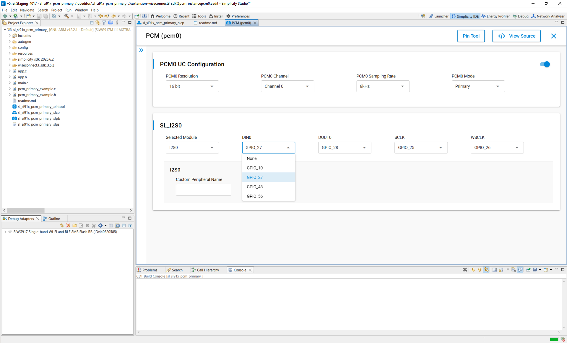
Or use the Pin Tool:
Step 4. (Optional) Configure in Code#
You can refine the generated configuration in application code, such as:
PCM mode
resolution and sampling rate
transfer type
Refer to the PCM API Reference for configuration structure and enumeration definitions.
Terminology Note:
In signal names, use DIN (data in) and DOUT (data out).
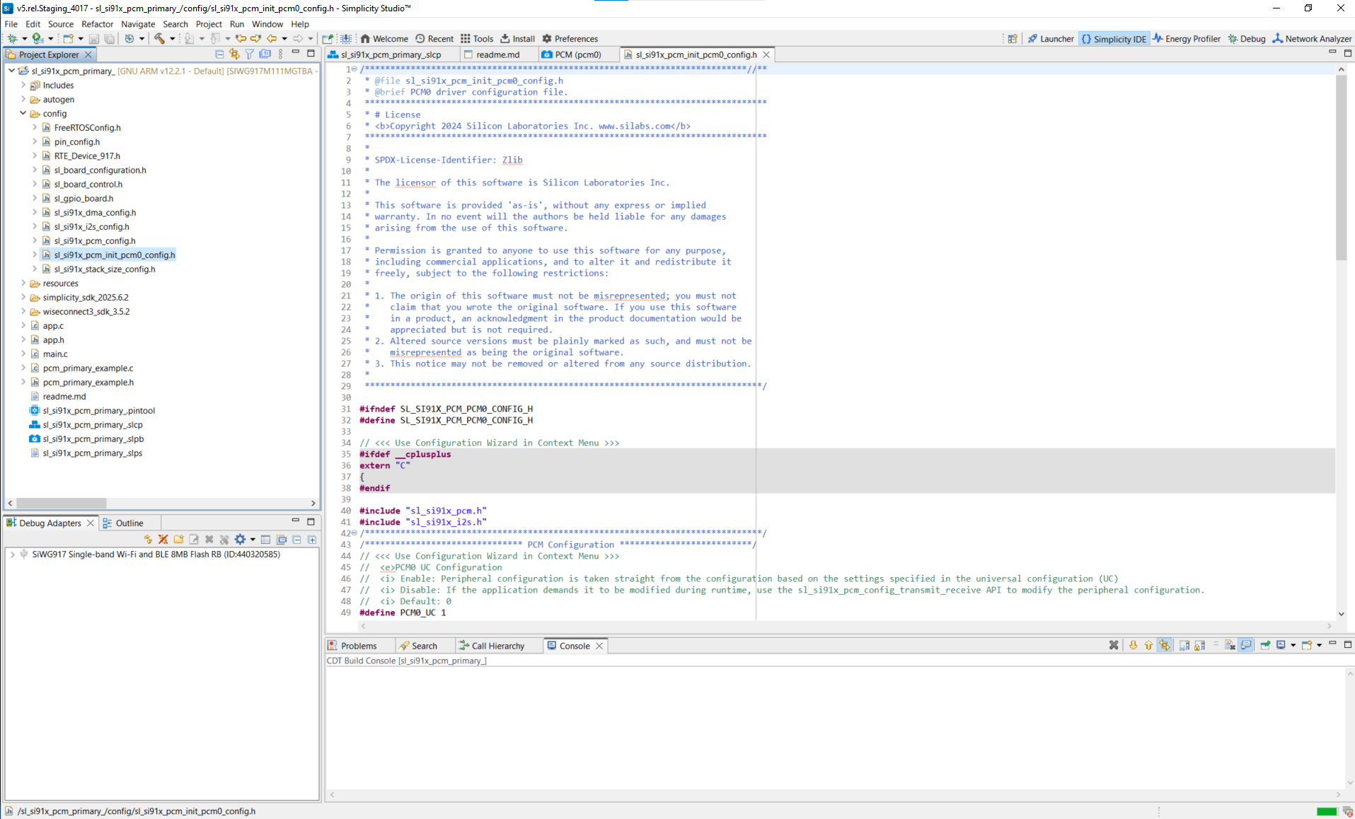
Step 5. Generate Initialization Code#
When you add or modify PCM components, Simplicity Studio generates the driver and configuration files.
In the UC configuration UI, select View Source to review the generated files.
Step 6. Initialize PCM in Your Application#
Driver locations
/wiseconnect3_sdk_<version>/components/device/silabs/si91x/mcu/drivers/unified_api/inc/sl_si91x_pcm.h
/wiseconnect3_sdk_<version>/components/device/silabs/si91x/mcu/drivers/unified_api/src/sl_si91x_pcm.cExample
sl_status_t status;
sl_i2s_handle_t pcm_handle; // Handle type as defined by the SDK
uint32_t pcm_sampling_frequency = SL_I2S_SAMPLING_RATE_16000;
uint32_t pcm_resolution = SL_I2S_RESOLUTION_16;
uint16_t mode = SL_I2S_MASTER;
void callback_event(uint32_t event);
status = sl_si91x_pcm_init(PCM_INSTANCE, &pcm_handle);
if (status != SL_STATUS_OK) {
DEBUGOUT("PCM Initialization fail\r\n");
// handle error
} else {
DEBUGOUT("PCM Initialization success\r\n");
}
status = sl_si91x_pcm_register_event_callback(pcm_handle, callback_event);
if (status != SL_STATUS_OK) {
DEBUGOUT("PCM user callback register fail\r\n");
// handle error
} else {
DEBUGOUT("PCM user callback register success\r\n");
}
status = sl_si91x_pcm_set_configuration(pcm_handle, pcm_sampling_frequency, pcm_resolution, mode);
if (status != SL_STATUS_OK) {
DEBUGOUT("PCM configuration set fail\r\n");
// handle error
} else {
DEBUGOUT("PCM configuration set success\r\n");
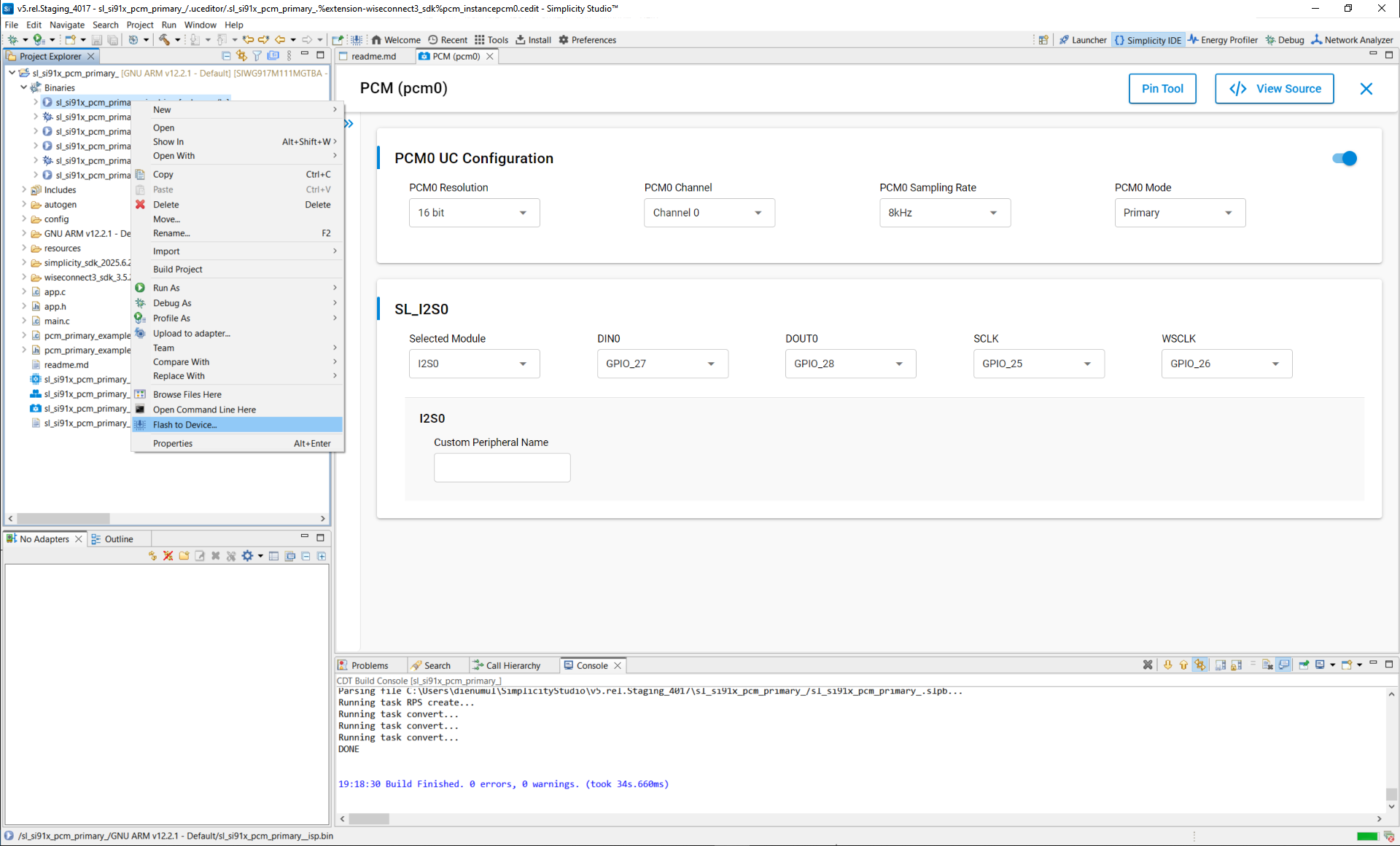
}Step 7. Build, Flash, and Test#
Step-by-step
Build your project in Simplicity Studio.
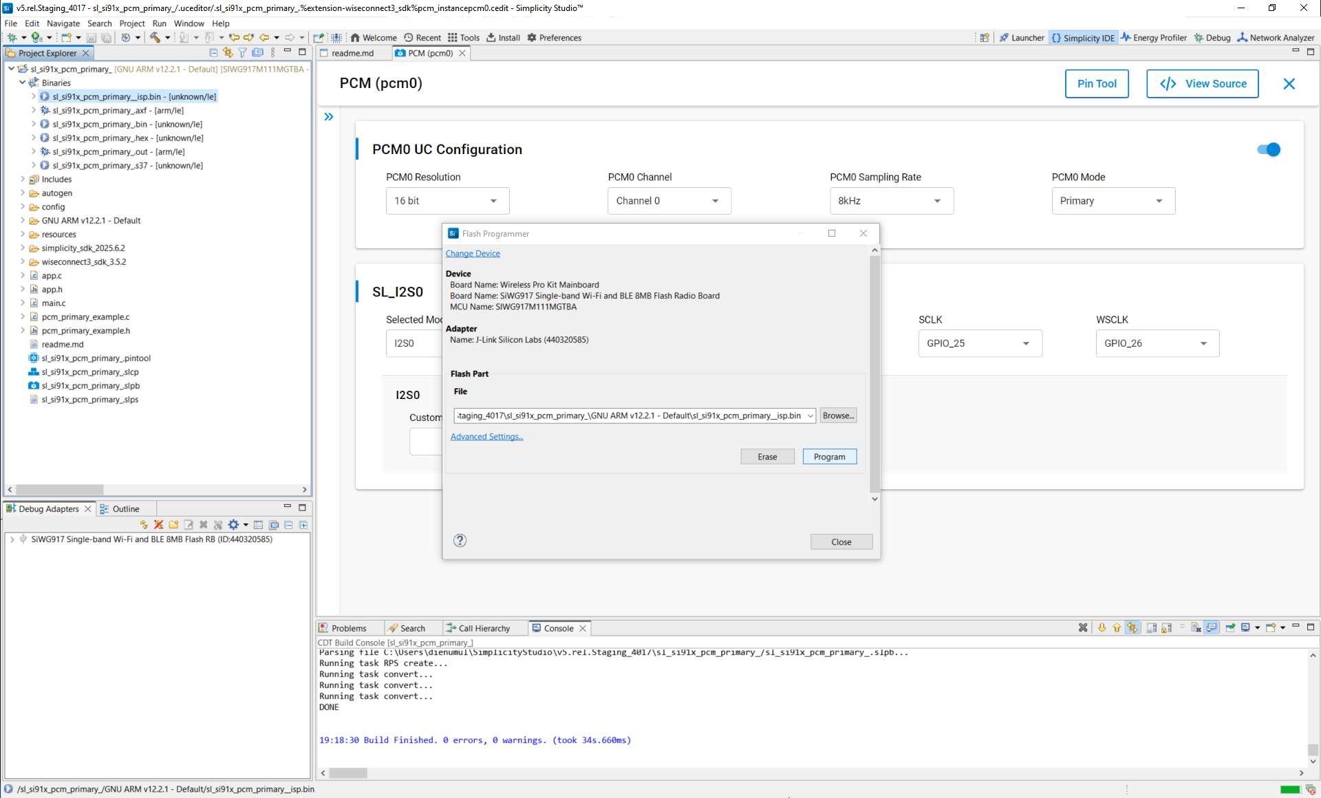
Flash the firmware to your Si91x device.
Verify PCM operation using the serial console or debugger.
Connected devices view
Connect devices
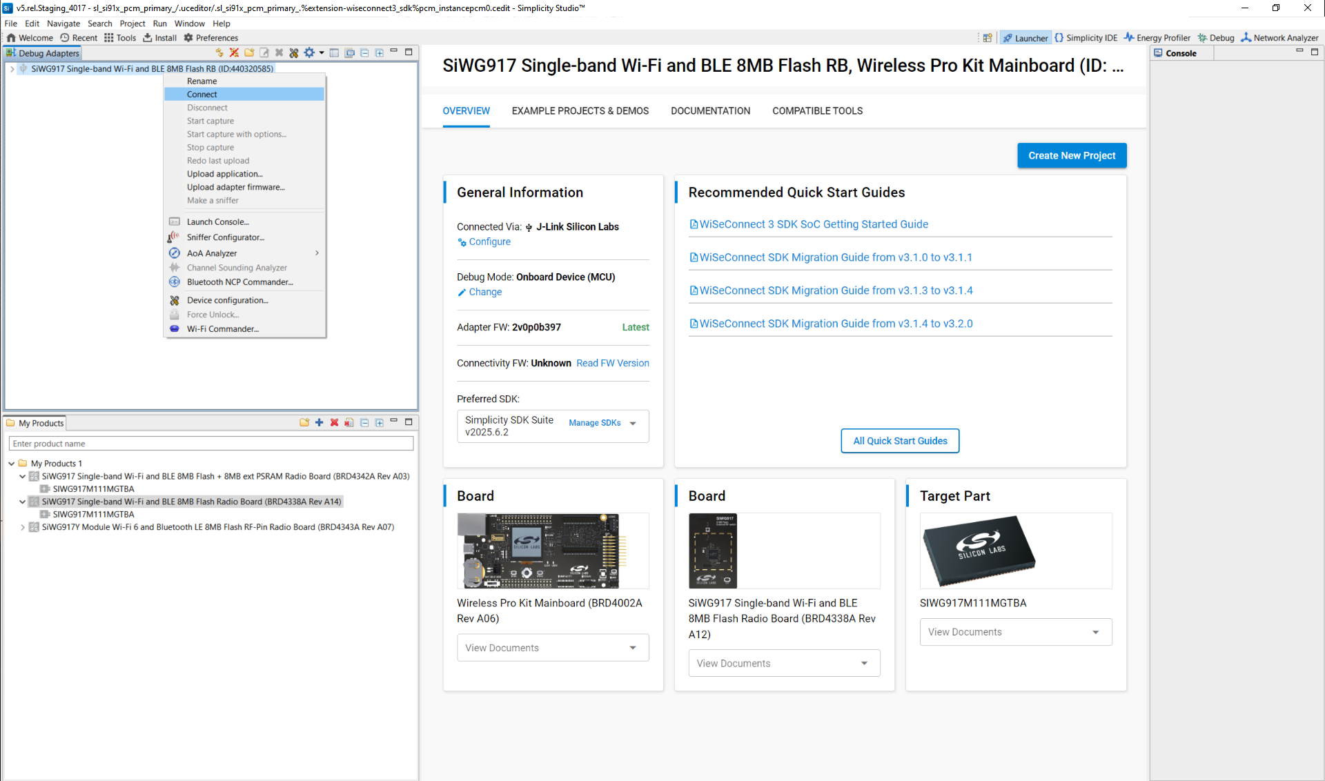
Launch console
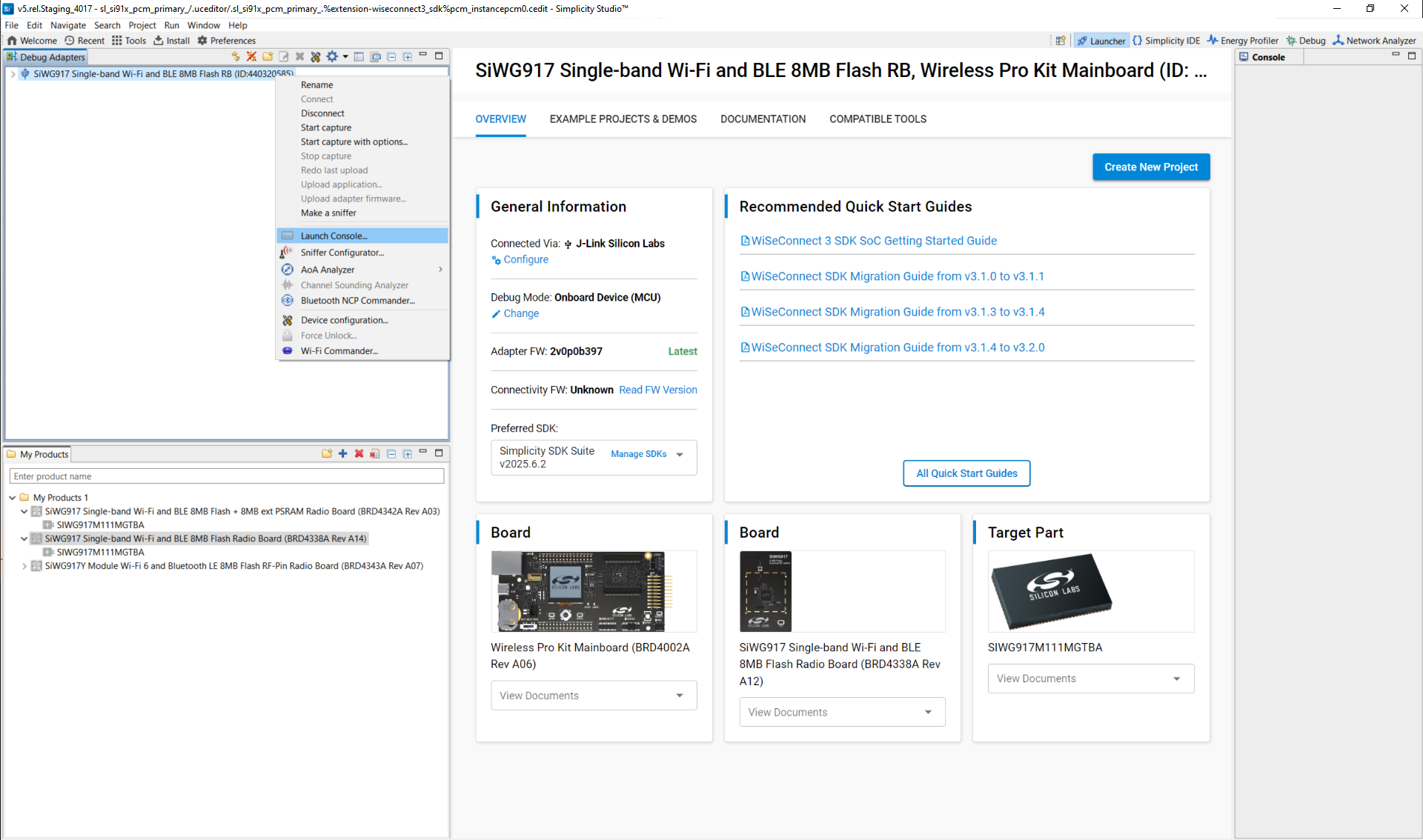
View current launch settings
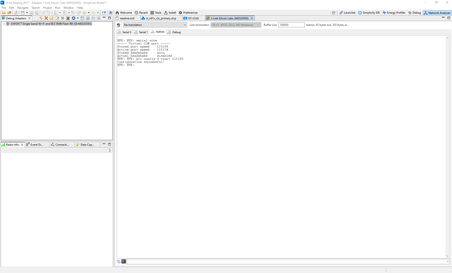
How to view logs
Open the console and select the serial1 tab.
Place the cursor in the text entry field at the bottom.
Press Enter to activate the console.
Primary log example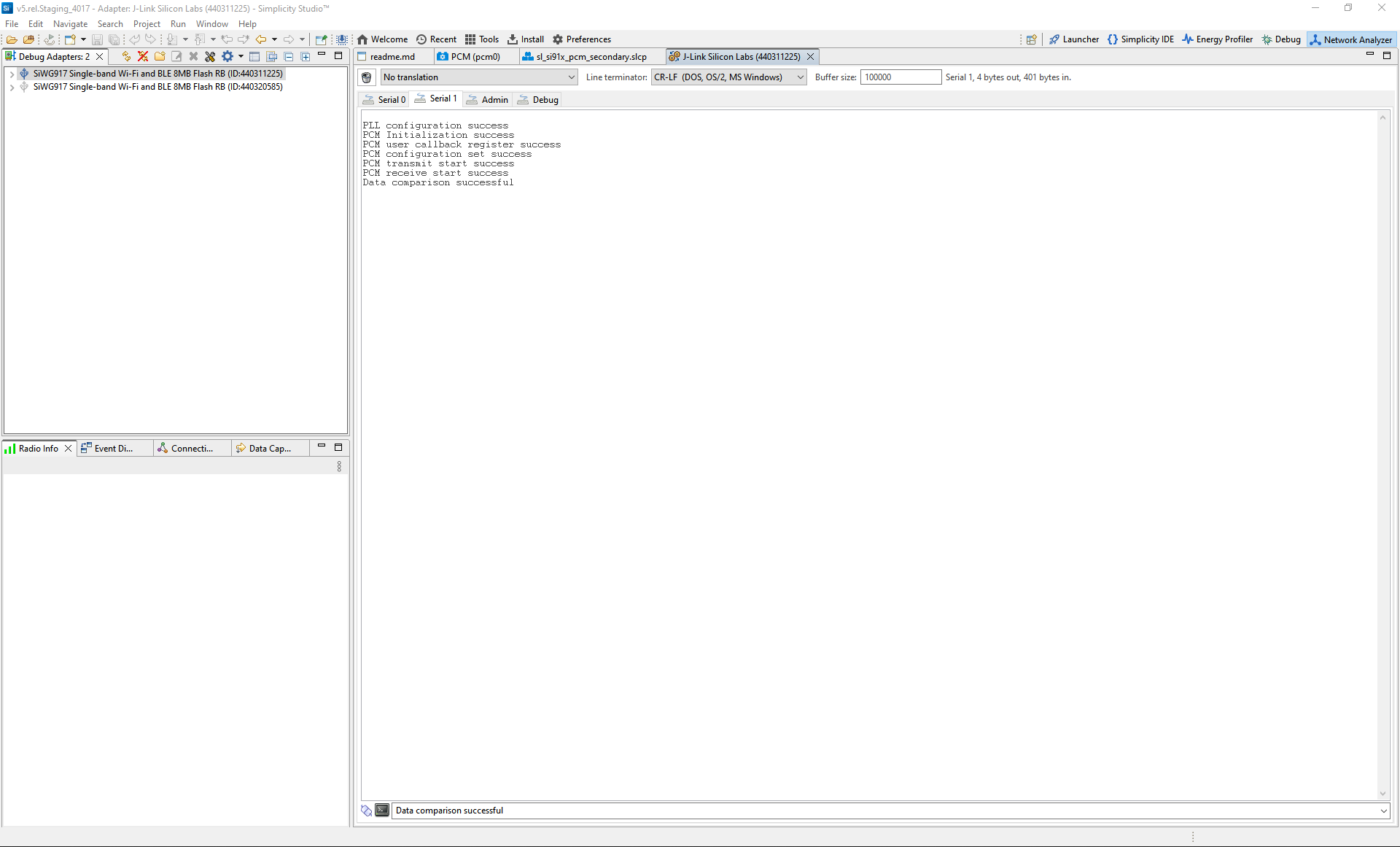
Secondary log example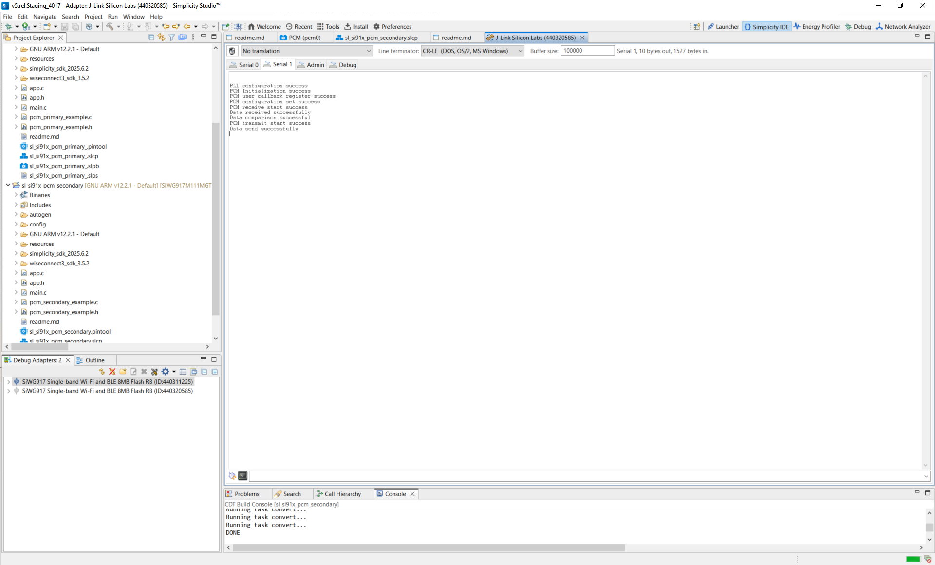
Note:
You can also use terminal programs such as Tera Term or PuTTY instead of the VCOM console.
Reference#
Structure reference: sl_i2s_xfer_config_t
Related example projects
WiSeConnect SDK PCM peripheral examples
SL Si91x – PCM Loopback
SL Si91x – PCM Primary
SL Si91x – PCM Secondary