Pulse Code Modulation (PCM) Debugging and Error Handling#
This section describes how to debug Pulse Code Modulation (PCM) connections and handle driver-level errors on the SiWx917 platform. It covers recommended hardware setup, signal inspection, logic analyzer usage, and recovery techniques for common PCM issues.
Common Debugging Tips#
Before debugging PCM-specific issues, review the official application-level guide for general debugging best practices:
WiSeConnect Debugging Guide.
Debugging PCM Connections#
Debugging typically starts with basic wiring inspection, followed by signal analysis using a logic analyzer and Simplicity Studio debug tools.
1. Visual Inspection and Connection Checklist#
Before using software debugging tools, verify physical connections:
Confirm Frame Sync (FSYNC), Bit Clock (BCLK), and Data (DIN/DOUT) lines are correctly connected between devices.
Ensure common ground between all connected boards.
Verify voltage compatibility between devices (for example, 1.8 V or 3.3 V).
Check for stable and clean clock signals using an oscilloscope or logic analyzer.
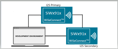
2. Interfacing with Si91x Development Kits (Primary/Secondary Setup)#
Use Si91x development kits for bring-up and debugging. Configure one board as the primary and another as the secondary.
Setup Steps#
Connect FSYNC, BCLK, and Data lines between the boards.
Ensure a shared ground and power both boards.
Program each board using Simplicity Studio.
Run PCM transactions and observe results using a Logic Analyzer (LA).
For custom secondary devices, verify that frame format, polarity, and sample rates match the primary device configuration.
Example Setup Diagram#
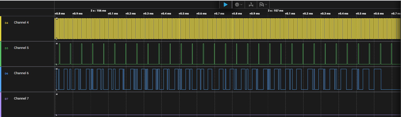
3. Using a Logic Analyzer#
A Logic Analyzer provides detailed visibility into PCM signals. Use it to confirm correct timing, alignment, and waveform integrity.
Setup Guidelines#
Connect probes to BCLK, FSYNC, and Data lines.
Enable PCM or I²S decoding in the analyzer software.
Set an appropriate threshold voltage and a minimum sample rate of 1 MHz.
Capture and validate:
Frame sync polarity and width.
Bit clock frequency and duty cycle.
Data order and word alignment (MSB-first or LSB-first).
FIFO underrun/overrun timing and interrupt response.
Example Capture#
4. Simplicity Studio Debug Integration#
Simplicity Studio can correlate firmware execution with Logic Analyzer data for deeper insight.
Workflow#
Open Simplicity Studio and select the Debug perspective.
Flash firmware and connect LA probes to PCM signal lines.
Capture PCM waveforms using the LA plug-in or an external analyzer.
Place breakpoints in your code to correlate execution with frame transitions.
Error Code Handling#
The PCM driver returns standardized status codes through APIs such as sl_si91x_pcm_transfer() and sl_si91x_pcm_receive(). These indicate operation success, errors, or hardware states.
Error Code | Description |
|---|---|
| Operation completed successfully. |
| General failure occurred. |
| Operation timed out (check clock or FSYNC). |
| Invalid configuration or argument provided. |
| PCM peripheral or DMA is busy. |
| PCM peripheral not initialized before use. |
If PCM enters an undefined or error state (for example, frame misalignment, clock loss, or FIFO underrun/overrun), perform a driver reset:
sl_si91x_pcm_deinit();
sl_si91x_pcm_init();Additional Debugging Tips#
Use the following best practices to accelerate PCM troubleshooting and ensure reliable audio operation on the SiWx917 platform:
Enable runtime logging:
UseDEBUGOUTstatements to print error codes, status messages, and callback events during PCM operation. This helps trace the exact point of failure.Verify signal integrity:
Confirm clean BCLK, FSYNC, and Data (DIN/DOUT) lines with a logic analyzer or oscilloscope. Look for missing edges, jitter, or inconsistent clock frequency.Check configuration consistency:
Ensure that both primary and secondary devices use the same sample rate, data width, and frame-sync polarity. Mismatched configurations commonly cause framing errors or distorted audio.Use DMA for continuous streaming:
Enable DMA-based PCM transfers to minimize CPU intervention and reduce the risk of underruns or overruns during real-time playback or recording.Adjust FIFO thresholds:
Fine-tune FIFO trigger levels for optimal balance between latency and throughput. Higher thresholds help avoid underruns in long data streams.Correlate firmware and hardware events:
Use Simplicity Studio’s Debug perspective in combination with a logic analyzer to align breakpoints with PCM frame events for root cause analysis.Monitor for underrun and overrun errors:
Add event-handling logic in callbacks to detect and respond to FIFO underruns and overruns. Use these logs to optimize buffer size and interrupt priority.Inspect clock domain stability:
Ensure the PCM peripheral’s clock source is stable and active throughout the operation, especially when switching between power states (PS3 ↔ PS4).Reinitialize after low-power transitions:
After waking from deep-sleep states, callsl_si91x_pcm_init()to reconfigure the PCM peripheral and restore synchronization.Use reference examples as baselines:
Start from the WiSeConnect SDK PCM examples (Primary, Secondary, Loopback) before customizing. These examples include verified configurations for timing and DMA setup.
Tip: To maintain consistent audio quality, always validate PCM timing using a Logic Analyzer when modifying frame size, sample rate, or polarity.