UART and USART Architecture#
The SiWx917 includes three Universal Asynchronous Receiver/Transmitter (UART) controllers:
USART0 (UART0): Located in the MCU High-Performance (HP) domain. Operates as a classic UART (asynchronous) or as a USART (synchronous/asynchronous).
UART1: Located in the HP domain. Operates as an asynchronous UART.
ULP_UART: Located in the Ultra-Low-Power (ULP) subsystem. Optimized for low-power, always-on communication use cases.
These peripherals provide reliable serial communication for sensors, modems, and host interfaces across performance and low-power domains.
UART Data Format Overview#
A UART/USART serial frame defines the structure for transmitting one character.
The frame can include configurable data bits, parity, and stop bits depending on communication requirements.
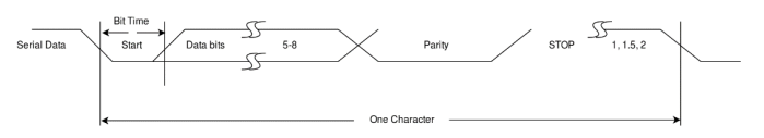
Figure: UART Serial Data Frame Format
UART Block Diagram Overview#
The UART block diagram illustrates internal transmit, receive, and control paths, including FIFO buffers and status logic.
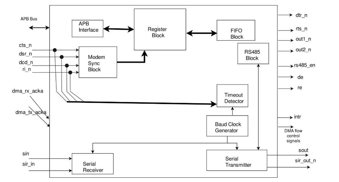
Figure: UART Internal Block Diagram
USART Block Diagram Overview#
The USART block diagram expands UART functionality by adding synchronous communication logic, including clock generation and duplex modes.
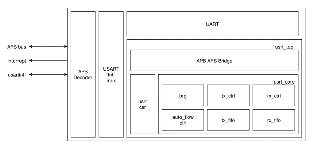
Figure: USART Internal Block Diagram
UART and USART Software Architecture#
The UART/USART software architecture for SiWx917 is modular and layered, ensuring portability and scalability across projects.
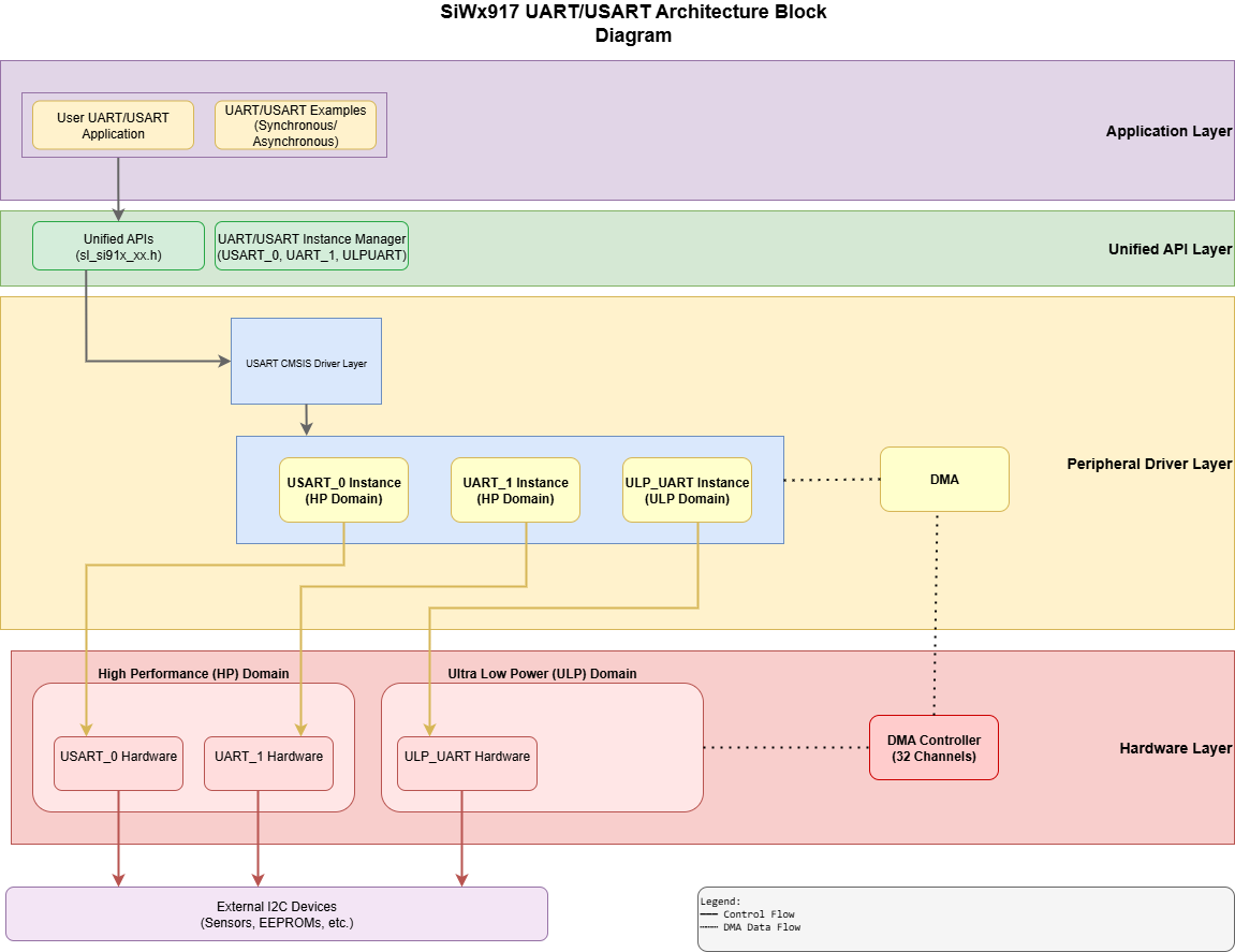
Figure: UART/USART Software Architecture Stack
Core Components#
The UART/USART driver stack consists of the following layers:
Layer | Description |
|---|---|
Application Layer | User-level application or example code that calls the UART/USART APIs. |
SL Driver Layer | High-level driver providing unified APIs for initialization, configuration, and data transfer. |
CMSIS-Driver Layer | ARM-standardized interface for portability and middleware integration. |
Peripheral Driver Layer | Low-level driver handling register access, interrupt management, and FIFO control. |
Hardware Layer | The physical UART/USART peripheral within the SiWx917 SoC. |
Benefits of the Layered Architecture
Abstracts hardware complexity with a consistent API across UART and USART instances.
Simplifies modular and reusable code development.
Supports both high-performance and low-power modes.
Enables efficient DMA-driven communication.
Maintains clear separation of responsibilities for better maintainability and debugging.
Example Directory Structure (wiseconnect3)#
wiseconnect3/
├── cmsis_driver/
│ ├── usart.c
│ └── usart.h
├── peripheral_drivers/
│ ├── rsi_usart.c
│ └── rsi_usart.h
├── unified_api/
│ ├── sl_si91x_usart.c
│ └── sl_si91x_usart.h
├── examples/
├── sl_si91x_uart/
├── sl_si91x_ulp_uart/
├── sl_si91x_usart_async/
├── sl_si91x_usart_sync_master/
└── sl_si91x_usart_sync_slave/Clock Architecture and Timing#
The UART/USART peripheral operates using a programmable clock source.
The baud rate is derived from the input clock and configured through hardware registers.
UART and USART Variants#
High-Performance UART/USART#
Purpose: Provides serial communication for peripherals, modems, and data sets.
Features:
Multi-drop RS485
5- to 8-bit character encoding with parity and configurable stop bits
Hardware auto flow control (RTS/CTS)
Programmable baud rate
FIFO and DMA support
Prioritized interrupts
Performance:
Up to 921,600 bps in UART mode
Up to 20 Mbps in USART mode
Use cases:
Console output
Sensor interfaces
External module communication
Ultra-Low-Power (ULP) UART#
Purpose: Provides energy-efficient communication during low-power modes.
Features:
Basic UART mode
DMA support in PS2 state
Wakeup through peripheral interrupt
No RS485
Auto flow control (RTS/CTS)
Performance:
Suitable for low-power applications
Use cases:
Low-power data logging
Wakeup signaling
Supported Operation Modes#
UART mode:
Asynchronous communication with start and stop bits
Optional parity
Programmable baud rate
USART mode:
Supports both synchronous and asynchronous communication
In synchronous mode, devices can act as master or slave
Supports full-duplex and half-duplex (single-wire) communication
Supported Features#
UART Controllers#
Multi-drop RS485 interface support
5-, 6-, 7-, and 8-bit character encoding with even, odd, or no parity
Configurable stop bits: 1, 1.5 (with 5-bit encoding), and 2
Hardware auto flow control (RTS/CTS)
Programmable baud rate, calculated as:
serial clock frequency / (16 × divisor)Maximum: 921,600 bps with a 118 MHz UART input clock
Standard baud rates: 300 to 921,600
Programmable fractional baud rate with support up to 5 Mbps
Programmable FIFO thresholds, maximum FIFO depth of 16, with DMA support
Prioritized interrupt identification
Note: RTS and CTS must both be enabled. Standalone RTS/CTS is not supported.
ULP UART#
DMA support in PS2 state
Auto flow control (RTS/CTS) is supported.
Note: ULP_UART does not support RS485.
USART Controller#
Supports synchronous and asynchronous modes
Provides full-duplex and half-duplex (single-wire) communication
Supports 5–8 bit character widths (plus 9-bit serial data support)
Offers baud rates up to 7.3 Mbps (UART mode, 118 MHz input clock) and 20 Mbps (USART mode)
Provides programmable FIFO thresholds with a maximum FIFO depth of 16 and DMA support
Generates interrupts for multiple events
RS485 Feature#
The SiWx917 UART/USART peripheral supports RS485 communication for multi-drop and industrial serial applications.
Key features include:
Dedicated driver enable (DE) and receiver enable (~RE) signals for bus control
Hardware and software half-duplex (RS485) and full-duplex (RS422) modes
9-bit addressing for multi-slave setups
For a complete RS485 example, see UART RS485 Example.
Transmission and Reception#
UART#
9-bit data transfer:
The UART supports 9-bit frames for multiprocessor (multi-drop) links. The 9th bit tags bytes as address (9th bit = 1) or data (9th bit = 0).Transmit modes:
Mode 0 (hardware address register): Write the address to the Transmit Address Register (TAR); write data bytes to the normal TX register(s) (THR/STHR).
Mode 1 (software packing): Write both address and data via THR/STHR; software sets/clears the 9th-bit marker per byte.
Receive path:
Hardware address match: Incoming address bytes are compared with the Receive Address Register (RAR). When matched, subsequent data bytes are admitted to RxFIFO; an address-received status/interrupt (e.g.,
LSR[8]) is raised.Software match: Your code evaluates the received address and may discard/reset the RxFIFO if the address is not of interest.
Note: Use 9-bit mode when multiple targets share the same bus and you want hardware to filter traffic to only the addressed node.
USART — Synchronous and Asynchronous Modes#
Asynchronous mode: Standard UART framing with start/stop bits and optional parity (same behavior as UART).
Synchronous mode: Clocked transfer using a dedicated serial clock line; no start/stop bits. One device acts as the controller (leader) supplying the clock, the other as the target (follower). Supports full-duplex or half-duplex (single-wire) configurations, depending on setup.
Note: Choose USART synchronous when you need clocked, low-latency transfers between two devices; choose asynchronous (UART or USART-async) for classic serial links without a shared clock.
Interrupts#
The UART/USART blocks generate prioritized interrupts. Typical sources include:
Receiver line status (errors): framing, parity, overrun
Receiver data available: Rx FIFO above threshold
Character timeout: no new Rx data for a programmed interval (FIFO mode)
Transmitter holding register empty (THRE): ready for the next byte/word
Modem status: CTS/DSR/RI/DCD changes (where applicable)
Busy detect: transmitter/shift logic still active
Enable or disable each source via the Interrupt Enable Register (IER) and read the Interrupt Identification Register (IIR) to identify the active interrupt.
Auto Flow Control#
Auto RTS: automatically de-asserts RTS when the Rx FIFO exceeds the threshold, and re-asserts when it falls below.
Auto CTS: automatically pauses transmission when CTS is inactive and resumes when CTS is asserted.
Note: RTS and CTS must be enabled together for hardware auto flow control; standalone RTS-only or CTS-only operation isn’t supported.
Register Summary (Base Addresses)#
High-Performance (HP) domain:
UART0:
0x4400_0000USART0:
0x4400_0100UART1:
0x4502_0000
Ultra-Low-Power (ULP) domain:
ULP_UART:
0x2404_1800
Dependencies#
The UART/USART peripheral depends on both hardware and software interfaces for proper operation.
Hardware Dependencies#
General-purpose input/output (GPIO) controller: Routes UART/USART signals (TX, RX, RTS, CTS) to physical pins.
Direct memory access (DMA) controller: Enables non-blocking, high-throughput data transfers.
Software Dependencies#
sl_si91x_usart: Core driver for initialization, configuration, and data transfer.sl_si91x_gpio: GPIO driver for configuring pin assignments and signal routing.sl_si91x_dma: DMA driver for non-blocking, high-speed data transfers.
Simplicity Studio Project Configurator automatically manages clock, power, GPIO, and DMA dependencies when you add a UART/USART component.