UART and USART Debugging and Error Handling#
This guide explains how to debug and handle errors in Universal Asynchronous Receiver/Transmitter (UART) and Universal Synchronous/Asynchronous Receiver/Transmitter (USART) communication. It provides checklists, hardware and software debugging steps, error code handling, and additional troubleshooting methods.
Common Debugging Tips#
Start with general debugging practices before moving to advanced tools.
Refer to the official troubleshooting guide for application debugging: WiseConnect Debugging Guide.
Debugging UART/USART Connections#
Debugging connections involves checking hardware integrity, verifying configurations, and using specialized tools for signal analysis.
1. Visual Inspection and Connection Checklist#
Ensure the transmit (TX) and receive (RX) lines are correctly connected between devices.
Check that voltage levels are correct (for example, 3.3 V or 1.8 V).
Verify ground connections between all boards.
Confirm the correct pin mapping and alternate function selection for UART/USART pins.
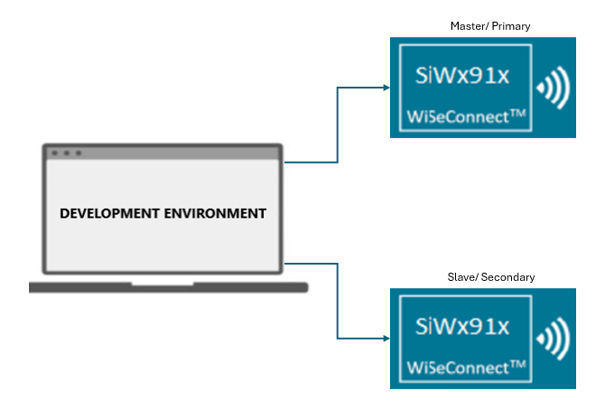
2. Interfacing with Si91x Development Kits (Full or Half Duplex Setup)#
When using Si91x development kits, configure one board as the UART/USART transmitter and the other as the receiver.
For RS485, ensure that driver enable (DE) and receiver enable (~RE) signals are correctly configured and toggled.
Use Simplicity Studio to flash and debug firmware on both boards. Run UART transactions and monitor activity with a logic analyzer and Studio debug tools.
For multi-drop or addressable setups, verify address-match logic and use 9-bit addressing if required.
Example setup diagram:
3. Using a Logic Analyzer for Debugging#
A logic analyzer (LA) helps confirm signal integrity and protocol decoding.
Connect LA probes to TX and RX lines.
Configure the LA for UART protocol decoding by setting the correct voltage threshold and baud rate.
Capture transactions during UART operations.
Use the analyzer to verify:
Start and stop bits
Data bytes
Parity and framing
Timing and baud rate accuracy
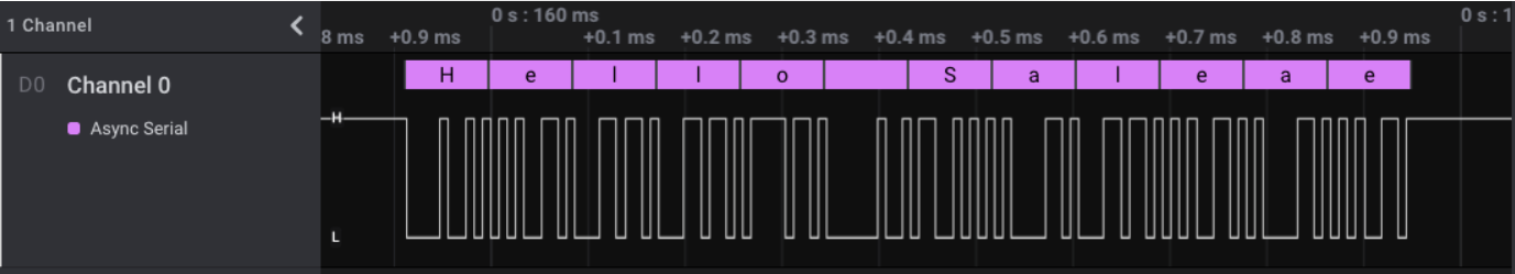
Example LA capture:
The following capture shows UART communication between two Si91x development boards using the blocking transfer example.
4. Debugging with Simplicity Studio and a Logic Analyzer#
Integrating Simplicity Studio with a logic analyzer provides synchronized hardware and software debugging.
Open Simplicity Studio and switch to the Debug perspective.
Flash firmware and connect the LA to TX and RX lines.
Use the LA plugin or external LA software to view UART signals.
Set breakpoints to correlate code execution with captured signals.
Error Code Handling#
The UART/USART driver uses standardized status codes to indicate
operation results. APIs such as sl_si91x_usart_send_data() and
sl_si91x_usart_receive_data() return these codes.
Error Code | Description |
|---|---|
SL_STATUS_OK | Operation completed successfully |
SL_STATUS_FAIL | General failure occurred |
SL_STATUS_TIMEOUT | Operation timed out |
SL_STATUS_INVALID_PARAMETER | Invalid input argument |
SL_STATUS_BUSY | Peripheral is currently busy |
SL_STATUS_NOT_INITIALIZED | Peripheral has not been initialized |
Use these codes to identify causes such as misconfigured pins, incorrect baud rates, or communication errors.
If the UART/USART peripheral enters an undefined or error state (for example, framing error, missed data, or improper sleep transition), reset the peripheral:
sl_si91x_usart_deinit(uart_handle);
sl_si91x_usart_init(UART_1, &uart_handle);Additional Debugging Tips#
Apply these additional methods for more effective debugging.
Use
DEBUGOUTor similar macros to print error codes and statuses in firmware.Check for shorted lines, incorrect voltage levels, or missing connections if communication fails.
Use a logic analyzer to diagnose timing mismatches, framing errors, or data loss.
For WiseConnect 3, use enhanced debug and protocol analysis features in Simplicity Studio.
Flow Control Debugging#
Ensure that flow control is configured correctly to prevent data loss.
Enable both Request to Send (RTS) and Clear to Send (CTS) for automatic flow control.
Use status registers to check First In, First Out (FIFO) levels and flow control status.
Poll the "FIFO full" status before writing to the transmitter FIFO.
Debugging in RS485 Mode#
For RS485 communication, verify the following:
DE and ~RE signals are correctly configured and toggled.
Multi-slave setups use 9-bit addressing with verified address-match logic.