Configurable Timer (CT) Initialization and Configuration#
The SiWx917 Software Development Kit (SDK) provides a unified Configurable Timer (CT) driver with flexible configuration options, multiple timer instances, and integration with power management features.
This section explains how to initialize and configure the CT peripheral using Simplicity Studio and the WiSeConnect SDK.
It covers automatic setup through the Universal Configurator (UC) system as well as manual configuration for advanced use cases.
For general SDK information, see Developing with the WiSeConnect SDK.
Startup Sequence#
CT initialization follows a structured, fail-safe startup sequence that ensures reliable operation.
System setup: Initializes device power and clock systems.
Peripheral enable: Activates the CT module in the MCU’s HP domain.
Configuration load: Applies UC or user-defined settings.
Interrupt / Direct Memory Access (DMA) configuration: Enables event-driven operations.
Validation: Confirms timer readiness before runtime use.
If any step fails, initialization halts immediately to prevent undefined states. This design guarantees predictable and deterministic timer behavior.
Step-by-step Configurable Timer Initialization and Configuration in Simplicity Studio#
This section walks through creating, configuring, and validating CT peripherals in Simplicity Studio.
Step 1. Create or Open Your Project#
Launch Simplicity Studio.
Create a new project for your SiWx917 device or open an existing one.
To explore reference implementations, select a Configurable Timer example project from the WiSeConnect SDK.
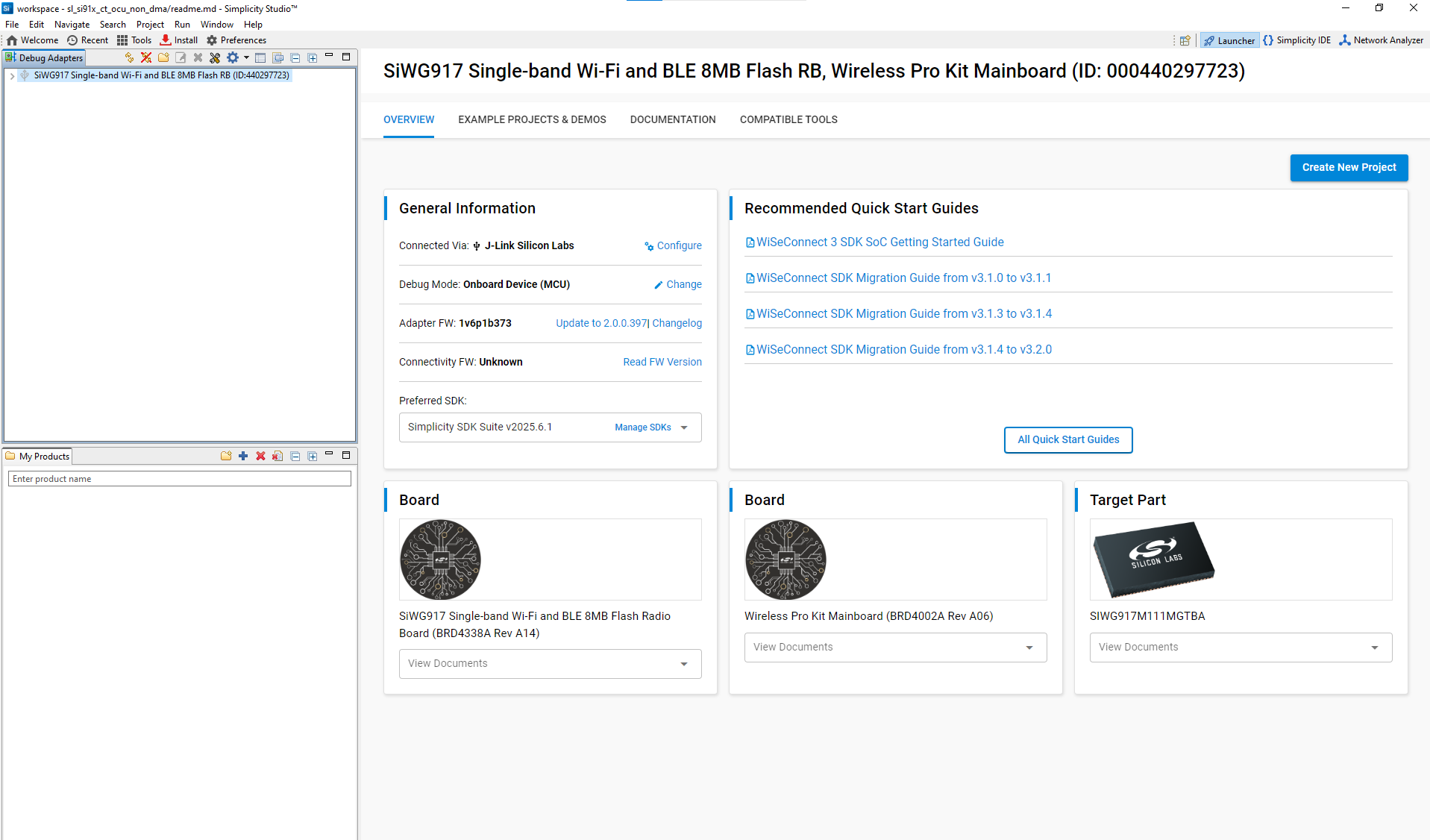
Connect your SiWx917 evaluation board. Simplicity Studio automatically detects it.
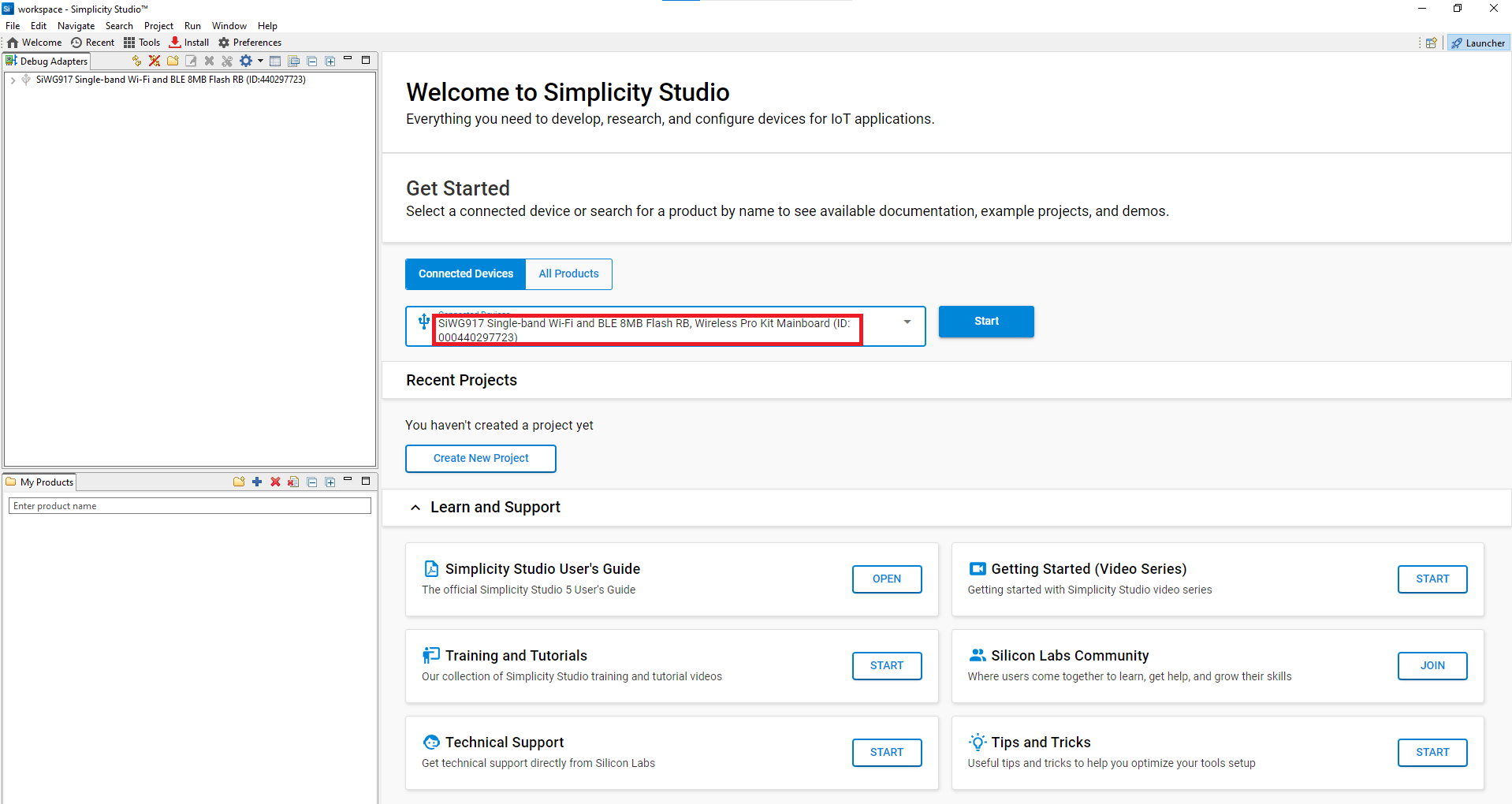
Figure: Automatic board detection in Simplicity StudioFrom Example Projects and Demos, choose a Configurable Timer example.
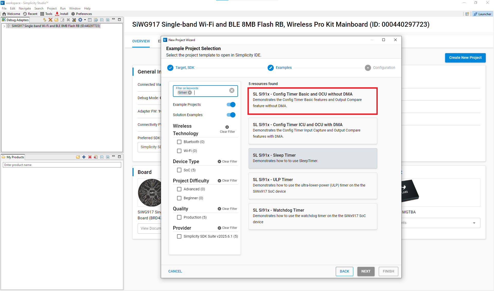
Figure: Selecting a Configurable Timer example projectClick Create to import the project into your workspace.
After you configure project details (name, location, SDK source), Simplicity Studio generates a directory structure. Most examples open a
readme.mdfile by default.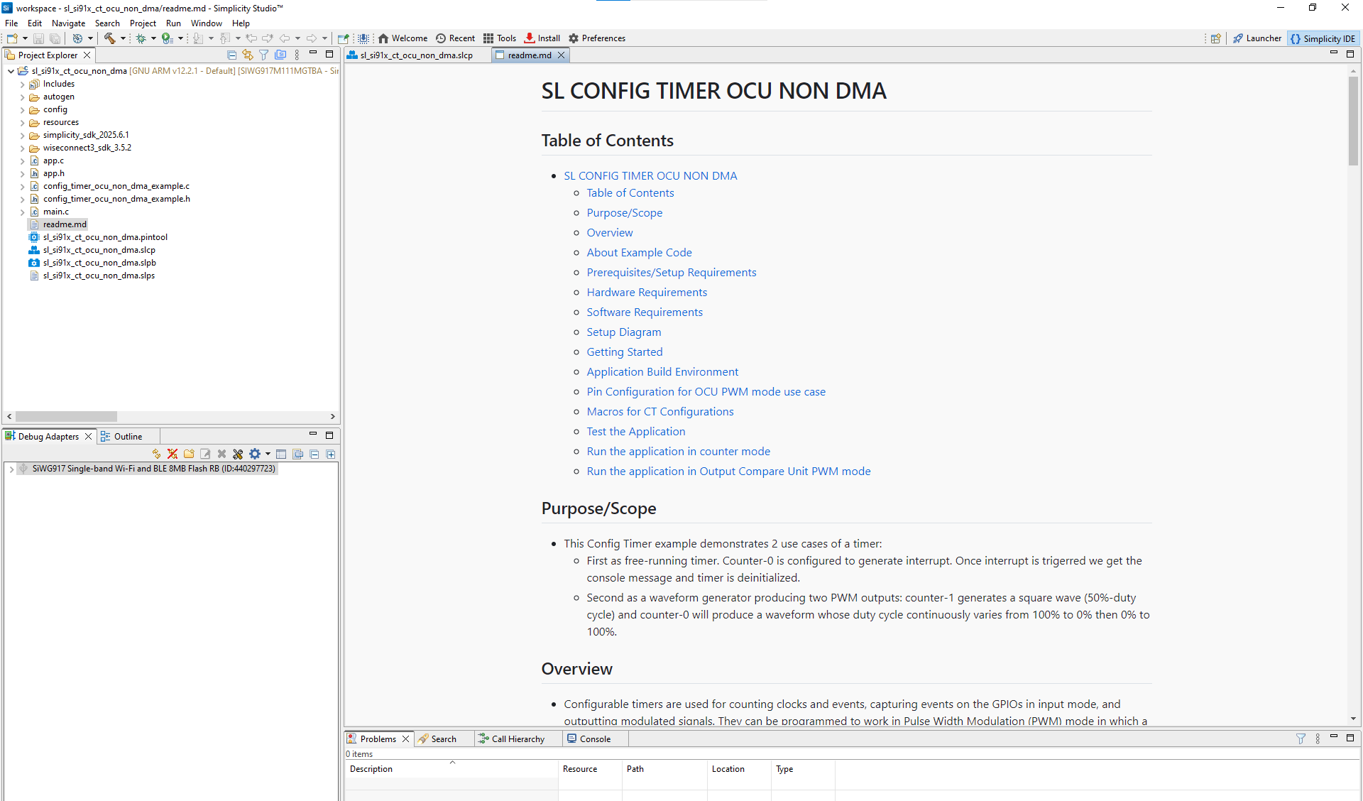
Typical Project Structure#
Folder/File | Description |
|---|---|
| Auto-generated configuration headers and linker scripts |
| Platform-specific configuration headers |
| Images and documentation files |
| HAL, CMSIS RTOS, and common libraries |
| Simplicity SDK platform layer and third-party libraries |
| WiSeConnect SDK components and libraries |
| Application logic files |
| Example source and header files |
| Application entry point |
| Example documentation |
| Project configuration file |
| Pin Tool configuration for CT |
| Project solution set file |
Step 2. Add the Configurable Timer Component#
Open the
.slcpconfiguration file.In the Software Components tab, search for Config Timer.
Ensure the component is installed and available in your project.
Step 3. Configure Config Timer with the Universal Configurator (UC)#
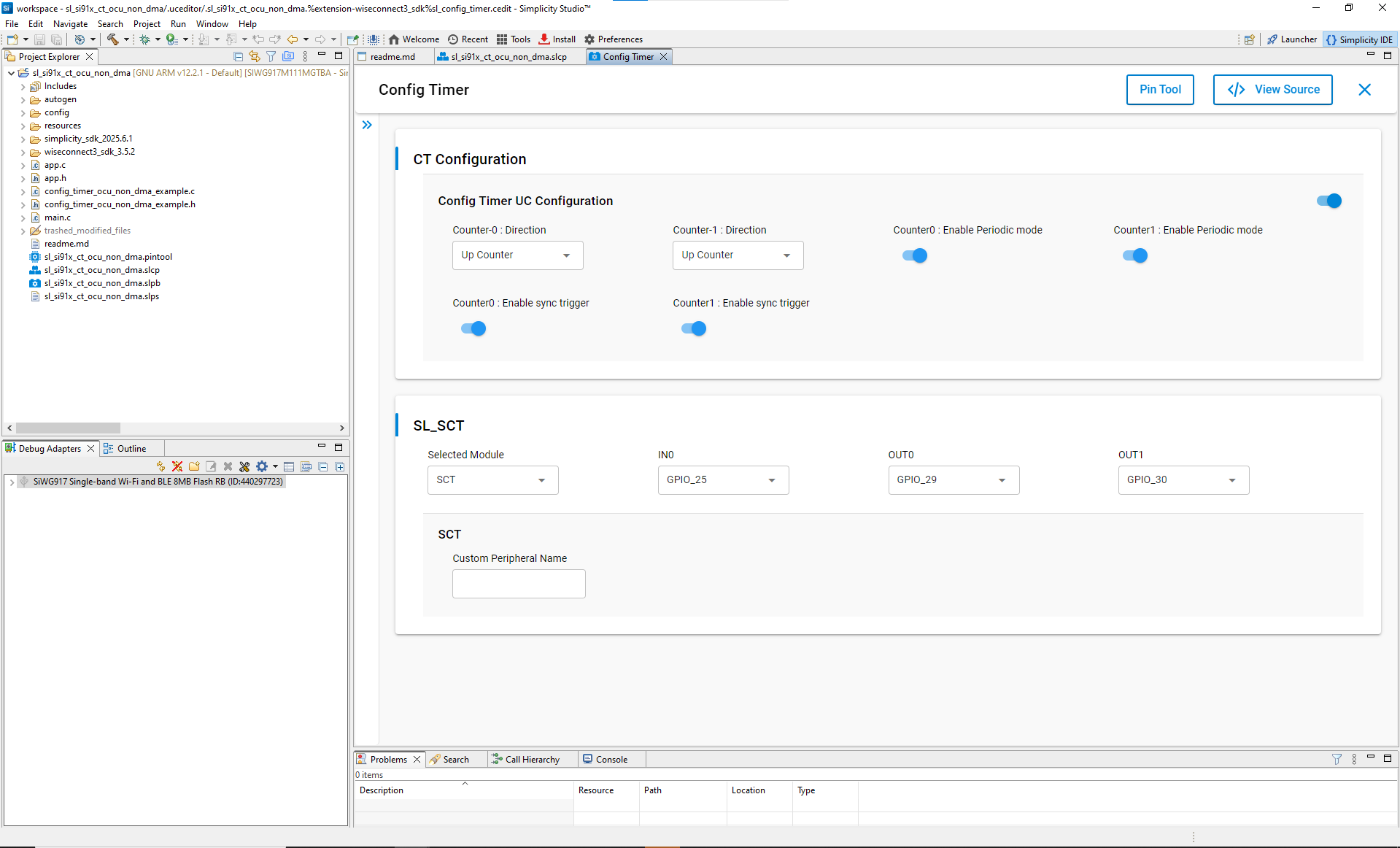
After installation, in the Software Components view, click Configure to open the UC graphical interface.
Set up timer parameters:
Counter Direction: Select Up, Down, or Up-Down for Counter0 and Counter1.
Periodic Mode: Enable or disable periodic operation.
Sync Trigger: Enable synchronization if using multiple counters.
Selected Module: Choose the Subsystem Configurable Timer (SCT).
Input/Output Pins (IN0/OUT0/OUT1): Assign purpose input/output (GPIO) pins for signals.
Valid pin options:
Signal | Available Pins |
|---|---|
IN0 | GPIO_25, ULP_GPIO_0 / GPIO_64, ULP_GPIO_4 / GPIO_68 |
OUT0 | GPIO_29, ULP_GPIO_4 / GPIO_68 |
OUT1 | GPIO_30, ULP_GPIO_5 / GPIO_69 |
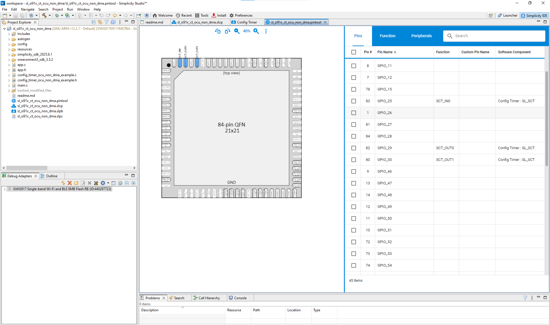
You can assign pins in two ways:
Dropdown Menu: Choose pins directly.
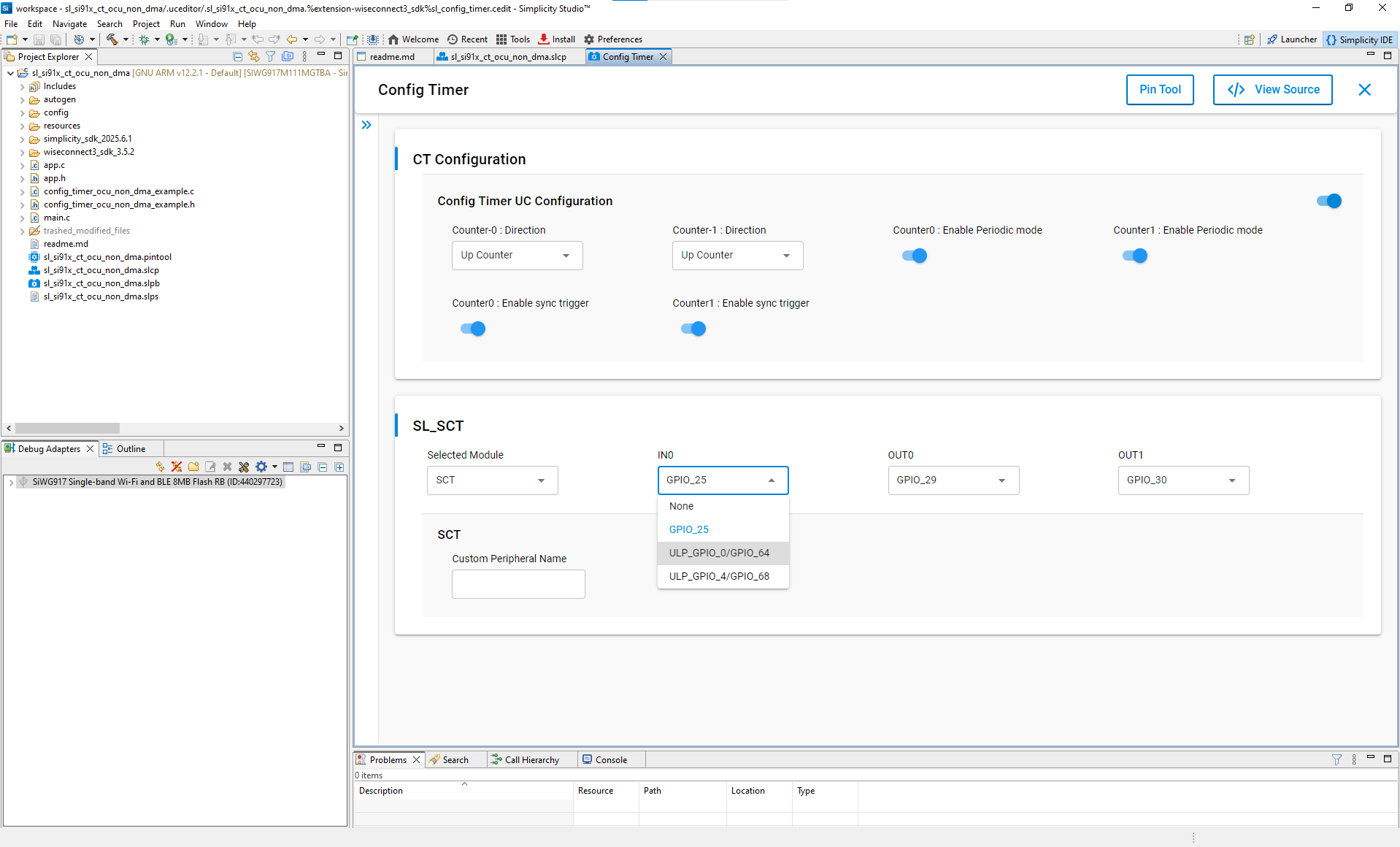
Pin Tool: Use Simplicity Studio’s graphical Pin Tool.
For a detailed list of configuration fields, see
sl_si91x_config_timer.h.
Step 4. Generate Initialization Code#
Once configuration is complete:
Simplicity Studio automatically generates CT driver and configuration source files.
Click View Source in the UC interface to verify generated code.
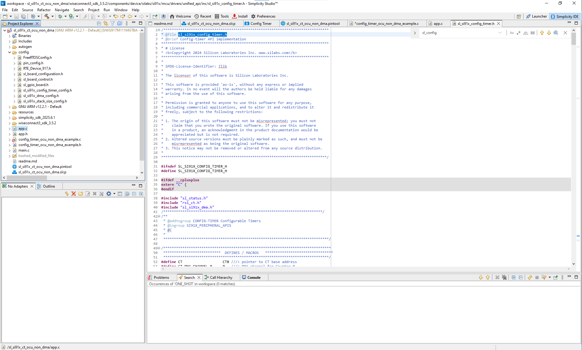
Figure: Auto-generated initialization code for CT
Generated files include:
sl_si91x_config_timer_init.c– Initialization sourcesl_si91x_config_timer_config.h– Configuration header
Step 5. Initialize Config Timer in Your Application#
Use the WiSeConnect SDK APIs to initialize the timer. Driver source and header files are located in:
/wiseconnect3_sdk_<version>/components/device/silabs/si91x/mcu/drivers/unified_api/inc/sl_si91x_config_timer.h
/wiseconnect3_sdk_<version>/components/device/silabs/si91x/mcu/drivers/unified_api/src/sl_si91x_config_timer.cExample initialization code:
// Initializing Configurable Timer instance
sl_status_t status = sl_si91x_config_timer_init();
DEBUGINIT();
if (status != SL_STATUS_OK) {
DEBUGOUT("sl_si91x_config_timer_init : Initialization failed, Error Code : %lu\n", status);
} else {
DEBUGOUT("Successfully initialized Configurable Timer\n");
}
// Configuring CT parameters from UC values
status = sl_si91x_config_timer_set_configuration(&ct_config);
if (status != SL_STATUS_OK) {
DEBUGOUT("sl_si91x_config_timer_set_configuration : Invalid Parameters, Error Code : %lu\n", status);
} else {
DEBUGOUT("Successfully configured CT parameters\n");
}
// Getting the match value for the timer
status = sl_si91x_config_timer_get_match_value(TIME_PERIOD_VALUE, &match_value);
if (status != SL_STATUS_OK) {
DEBUGOUT("sl_si91x_config_timer_get_match_value : Error Code : %lu\n", status);
} else {
DEBUGOUT("Successfully obtained CT match value\n");
}
// Setting up interrupt for match event
if (CT_COUNTER_USED == SL_COUNTER_0) {
ct_interrupt_flags.is_counter0_hit_peak_interrupt_enabled = true;
} else {
ct_interrupt_flags.is_counter1_hit_peak_interrupt_enabled = true;
}
// Registering callback for timer events
status = sl_si91x_config_timer_register_callback(on_config_timer_callback, callback_flag_data, &ct_interrupt_flags);
if (status != SL_STATUS_OK) {
DEBUGOUT("sl_si91x_config_timer_register_callback : Error Code : %lu\n", status);
} else {
DEBUGOUT("Successfully registered CT callback\n");
}
// Setting match value for the selected counter
status = sl_si91x_config_timer_set_match_count(SL_COUNTER_16BIT, CT_COUNTER_USED, match_value);
if (status != SL_STATUS_OK) {
DEBUGOUT("sl_si91x_config_timer_set_match_count : Error Code : %lu\n", status);
} else {
DEBUGOUT("Successfully set CT match count\n");
}
// Starting the selected counter with software trigger
status = sl_si91x_config_timer_start_on_software_trigger(CT_COUNTER_USED);
if (status != SL_STATUS_OK) {
DEBUGOUT("sl_si91x_config_timer_start_on_software_trigger : Error Code : %lu\n", status);
} else {
DEBUGOUT("Successfully started CT on software trigger\n");
}Step 6. Customize for Advanced Use Cases#
You can modify the generated configuration or initialization code to extend functionality beyond the default setup.
This includes:
Adding custom callback functions for timer events
Enabling or adjusting Direct Memory Access (DMA) settings for advanced data handling
Changing match values, synchronization behavior, or trigger conditions dynamically
Integrating CT with other peripherals for coordinated operation
For complete examples and implementation details, seeconfigurable-timer-usage-scenarios.md.
Step 7. Build, Flash, and Test#
After configuration, build and validate your project using Simplicity Studio.
You can test your application output using the Virtual COM (VCOM) console built into Simplicity Studio, or external serial tools such as Tera Term or PuTTY.
Step-by-Step: Build, Flash, and Test#
Build the project.
Compile your project in Simplicity Studio to generate the firmware image.
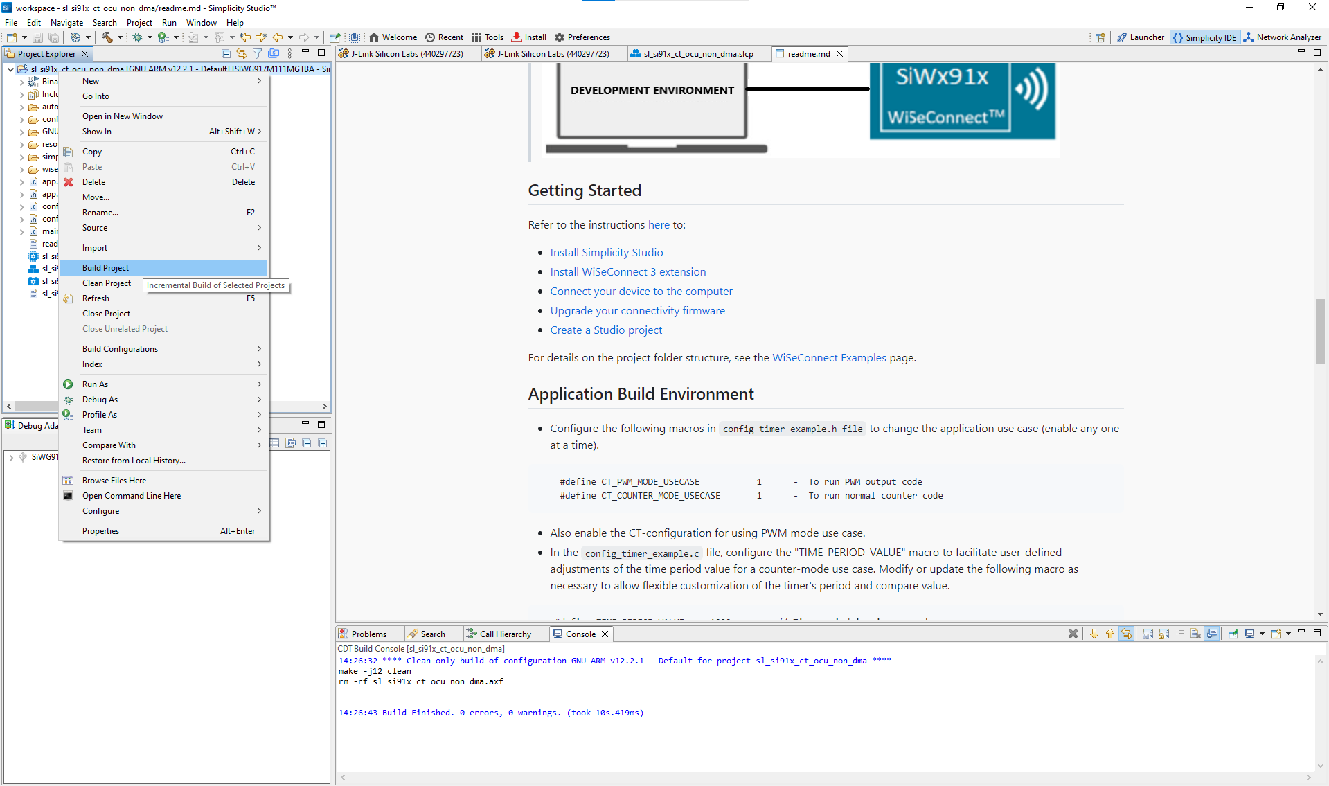
Figure: Building the Configurable Timer project in Simplicity StudioFlash the firmware to your SiWx917 device.
Once the build completes, flash the firmware image to your SiWx917 evaluation board.
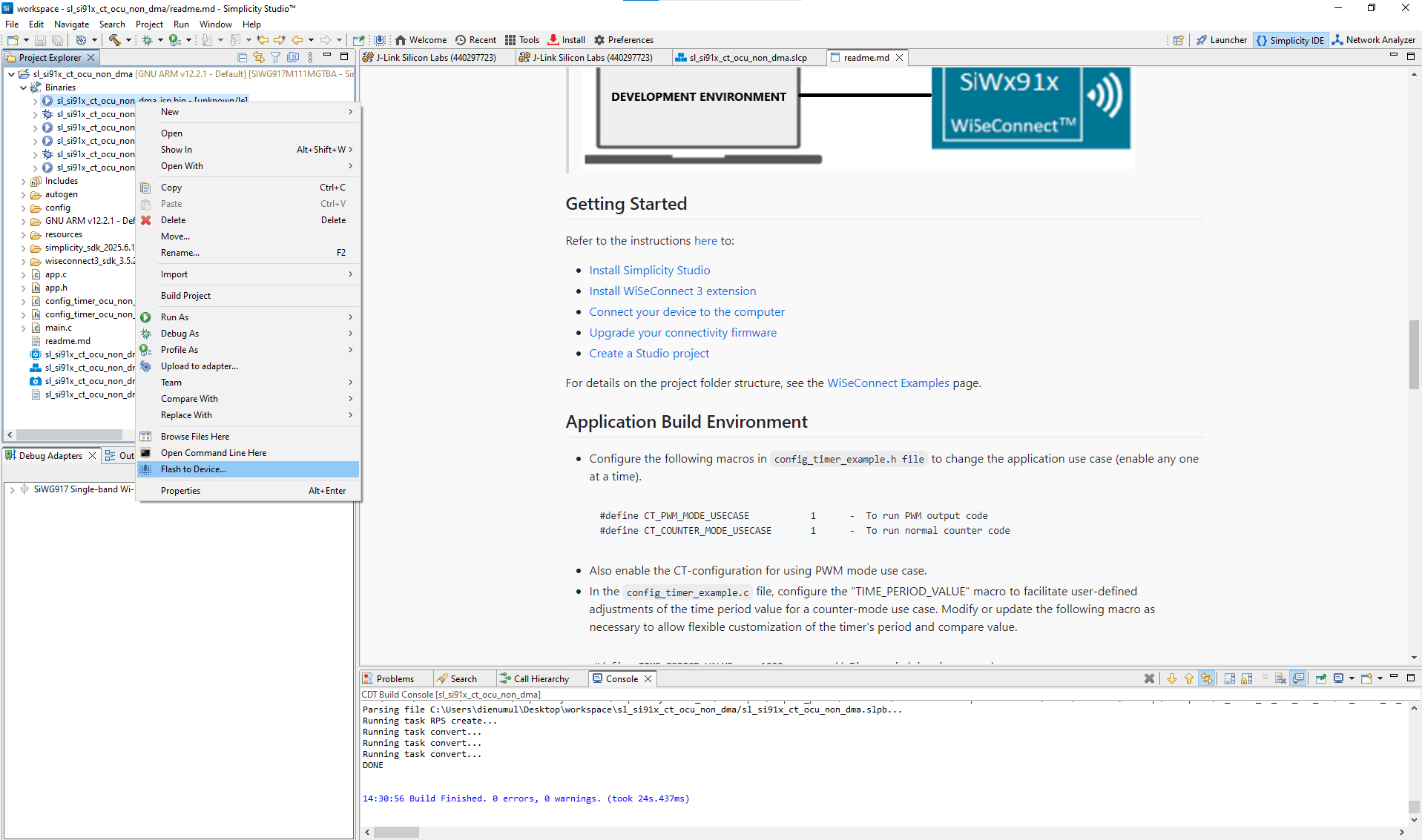
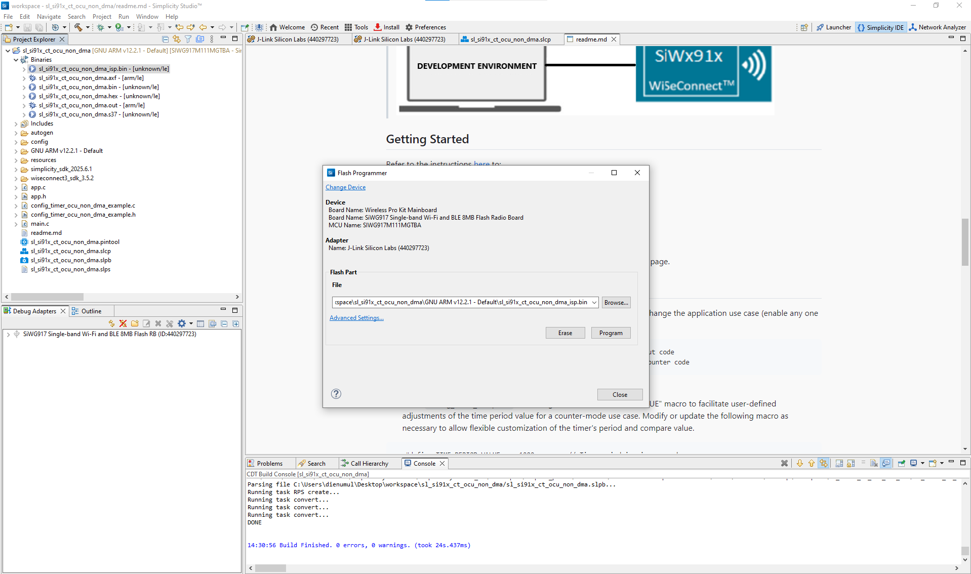
Figure: Programming the SiWx917 device with CT firmwareVerify Configurable Timer operation.
Use the VCOM console or a serial terminal to observe log output and confirm correct timer operation.
Access connected devices
Connect to your target board
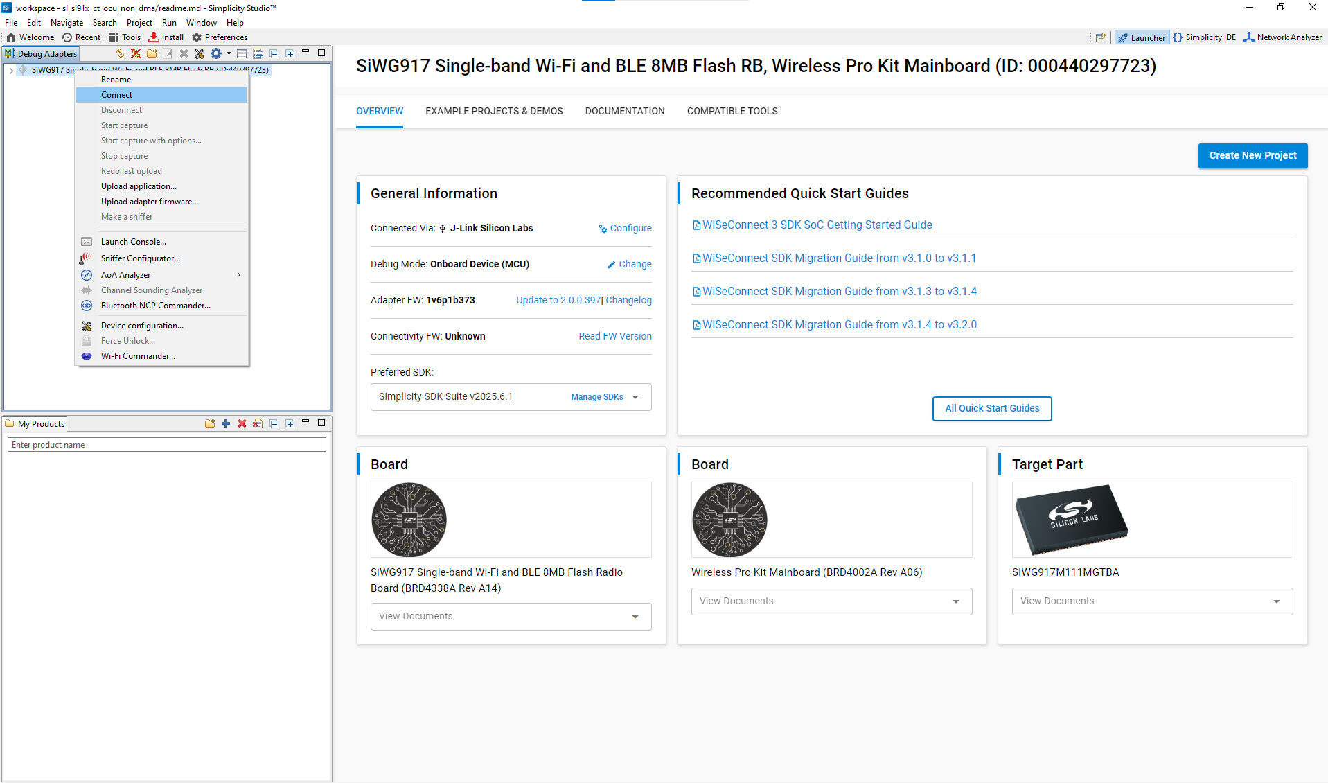
Launch the console
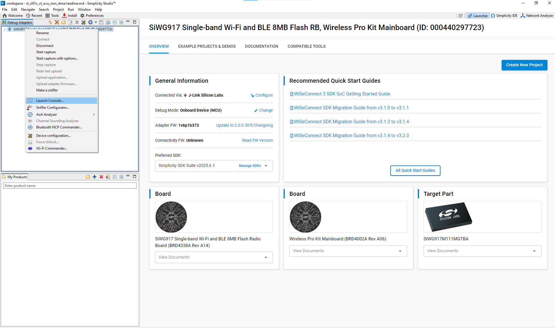
View or modify console settings
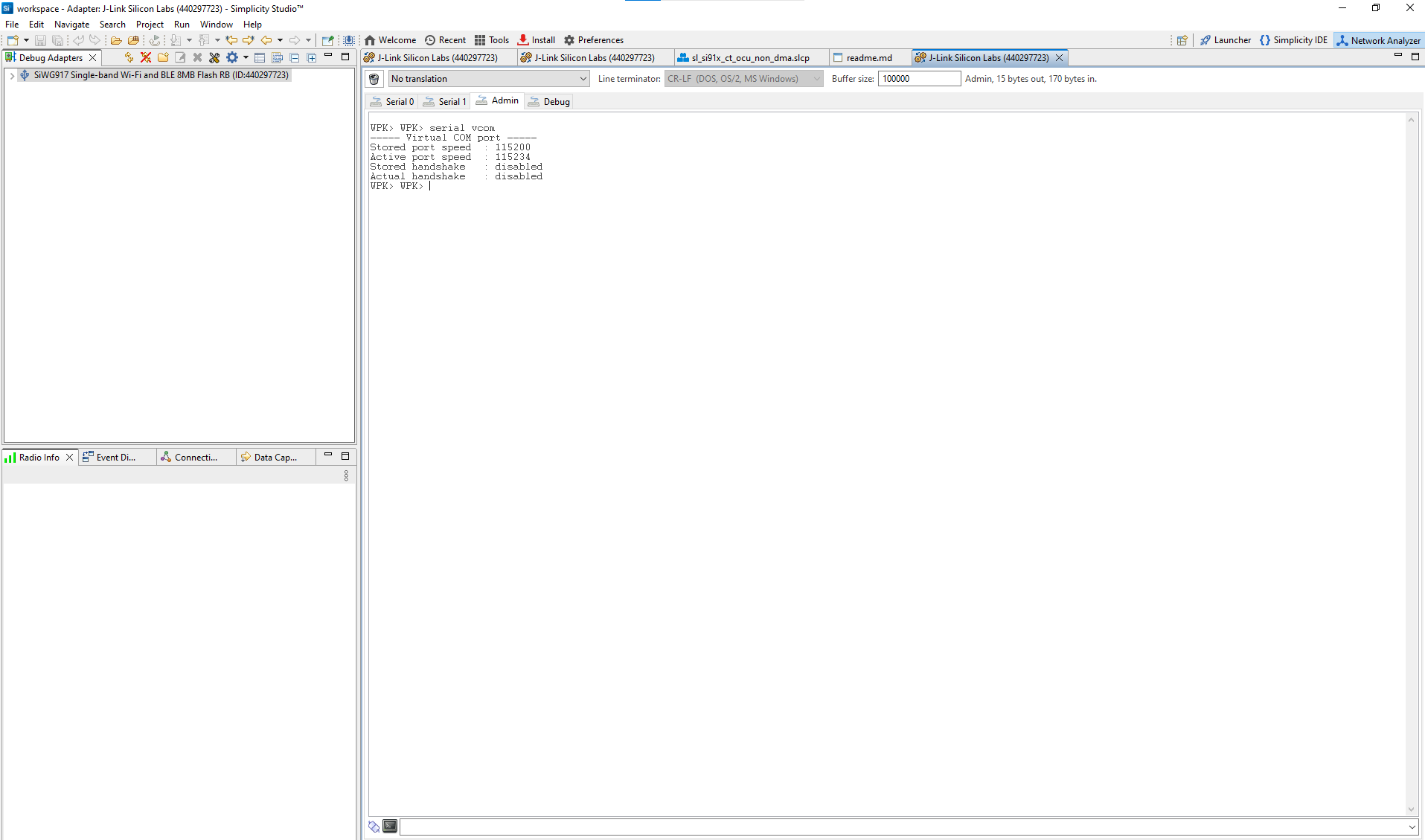
To view logs:
Open the console and select the serial1 tab.
Click inside the console entry field.
Press Enter to activate serial logging.
Example Output
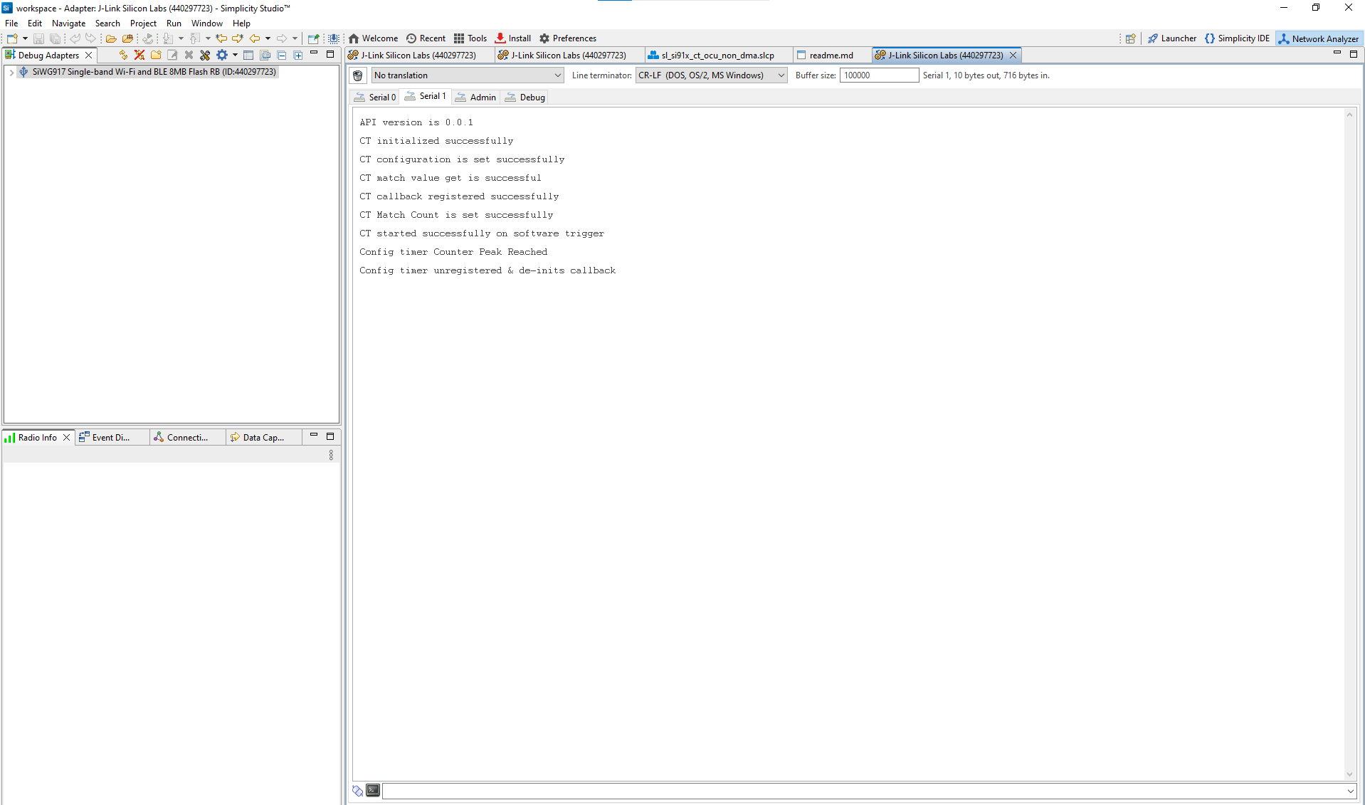
Figure: Example Configurable Timer log output showing initialization and runtime status
Tip: The log output confirms whether initialization, configuration, and event callbacks are working correctly. If no output appears, check that your board is connected, powered, and flashed with the correct build configuration.
References#
Related Example Projects
Explore the WiSeConnect SDK Peripheral Examples for complete CT demonstrations:
WiSeConnect SDK Config Timer Peripheral Examples
Example | Description |
|---|---|
SiWx917 – Config Timer Basic and OCU (Non-DMA) | Demonstrates basic PWM and Output Compare Unit (OCU) operation without DMA. |
SiWx917 – Config Timer ICU and OCU (With DMA) | Shows Input Capture Unit (ICU) and OCU configurations using DMA for advanced timing applications. |