Configurable Timer (CT) Debugging and Error Handling#
The Configurable Timer (CT) on the SiWx917 is a flexible peripheral for generating pulse-width modulation (PWM) signals, scheduling precise timed operations, and synchronizing with external events.
Effective debugging of CT operations requires careful inspection of hardware signals, verification of configuration parameters, and consistent handling of returned application programming interface (API) status codes.
This section outlines debugging procedures, recommended analysis tools, and standardized error handling for the Configurable Timer.
Common Debugging Tips#
Debugging embedded systems typically involves both hardware validation and software inspection. For Configurable Timer development, start with basic signal verification before analyzing firmware-level issues.
For comprehensive troubleshooting steps, see the WiSeConnect Debugging Guide.
Debugging Configurable Timer Operations#
Follow a structured debugging approach:
Inspect hardware and connections.
Capture timer signals using measurement tools.
Validate runtime configuration and interrupt behavior in Simplicity Studio.
1. Visual Inspection and Hardware Verification#
Before investigating software-level issues, confirm the hardware setup:
Verify general-purpose input/output (GPIO) pin configuration for timer input/output mapping.
Ensure the timer clock is enabled in the high-performance (HP) domain.
Check that power domain settings support the timer’s operational state.
Confirm stable supply voltage during timer activity.
Verify interrupt routing and ensure callbacks are registered correctly in firmware.
Tip: A quick visual inspection and configuration review can eliminate most initialization and connectivity issues.
2. Verifying Timer Signals with SiWx917 Development Kits#
When using SiWx917 development kits, validate both the electrical setup and signal routing before debugging in software.
Setup Steps:
Connect GPIO pins configured as timer outputs to an oscilloscope or logic analyzer (LA).
For Output Compare Unit (OCU) or Waveform Generator (WFG) outputs, connect to a load or monitoring equipment.
Ensure the test equipment shares a common ground with the board.
Connect external triggers to the correct timer input pins, if used.
Flash firmware through Simplicity Studio, then verify signal behavior via the LA or oscilloscope.
Best Practice:
Confirm PWM signals for the expected frequency and duty cycle. For advanced configurations, validate synchronization across multiple timer channels.

Figure: Example Configurable Timer signal verification setup on a SiWx917 development kit.
3. Using a Logic Analyzer for Timing Analysis#
A logic analyzer provides high-precision insights into timer performance, synchronization, and output accuracy.
Procedure:
Attach LA probes to GPIO or timer output pins.
Configure sampling rate and voltage thresholds appropriately.
Capture timer cycles, compare match events, and observe PWM output transitions.
Analyze captured data to confirm alignment between expected and actual timing.
Validate the following with the Logic Analyzer:
Counter start and overflow events.
Compare match triggers and output responses.
PWM signal duty cycle and frequency.
Synchronization between multiple timer instances.
Example Capture:
The following trace demonstrates dual PWM outputs generated by the Configurable Timer:
CT Output 1: A steady square wave with a fixed 50% duty cycle.
CT Output 0: A variable PWM waveform that dynamically adjusts duty cycle between 0% and 100%.
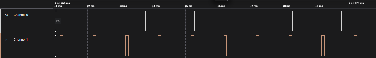
Figure: PWM waveform analysis using a logic analyzer.
4. Debugging with Simplicity Studio and Logic Analyzer#
Simplicity Studio integrates hardware and software debugging for efficient validation.
Steps:
Open Simplicity Studio and switch to the Debug perspective.
Flash the firmware to the SiWx917 board.
Connect LA probes to timer output pins.
Use Simplicity Studio’s Energy Profiler or external LA software to monitor signal activity.
Set breakpoints inside timer callbacks to correlate events with LA captures.
Monitor peripheral registers in the debug window to confirm real-time configuration and counter values.
Tip: Use Simplicity Studio’s combined debugging and profiling features to align captured signals with firmware-level event timing.
Error Code Handling#
The Configurable Timer driver returns standardized status codes for all API operations. Always check return values when initializing, configuring, or starting timers to ensure reliable behavior.
Standard Error Codes#
Error Code | Description |
|---|---|
| Operation completed successfully. |
| General failure occurred. |
| Operation timed out. |
| Invalid input argument provided. |
| Peripheral is currently busy or locked. |
| Timer peripheral has not been initialized. |
Tip: Log API return codes in debug builds to identify incorrect initialization sequences or invalid parameter combinations early.
Handling Undefined or Error States#
If the Configurable Timer enters an undefined or locked state due to configuration errors, power transitions, or invalid parameters, perform a peripheral reset to restore default settings.
sl_si91x_config_timer_deinit();
sl_si91x_config_timer_init();This reset clears invalid configurations and ensures the timer restarts from a stable, known state.
Note: Reinitialize the timer after system power changes or clock reconfiguration to prevent inconsistent timing behavior.