System Real-Time Clock (SYSRTC) Initialization and Configuration#
The Silicon Labs SiWx917 Software Development Kit (SDK) includes a unified System Real-Time Clock (SYSRTC) driver API that supports precise timekeeping, event scheduling, and low-power operation across embedded applications. The SYSRTC peripheral offers flexible configuration options, advanced timing modes, and seamless integration with the device’s power management framework.
This section explains how to initialize and configure SYSRTC using either:
The Universal Configurator (UC) in Simplicity Studio for automated setup, or
Manual initialization and programming through the SDK for advanced or specialized use cases.
Step-by-step instructions take you from basic startup to complex event scheduling and channel configuration, ensuring accurate and reliable real-time operation.
For detailed register and peripheral descriptions, see the SiWx917 Family Reference Manual.
For SDK-specific workflows, see Developing with the WiSeConnect™ SDK.
Startup Sequence#
The SYSRTC startup process follows a defined sequence to guarantee stable operation, predictable timing, and reliable error handling.
Each stage depends on the successful completion of the previous one. If any step fails, the initialization process halts immediately to prevent SYSRTC from entering an undefined or inconsistent state.
Step-by-Step SYSRTC Initialization and Configuration in Simplicity Studio#
This section explains how to set up SYSRTC on Si91x devices using Simplicity Studio and the WiSeConnect SDK.
Step 1. Create or Open a Project#
Launch Simplicity Studio.
Create a new project for your Si91x device or open an existing one.
For demonstration, select one of the SYSRTC example projects from the WiSeConnect SDK.
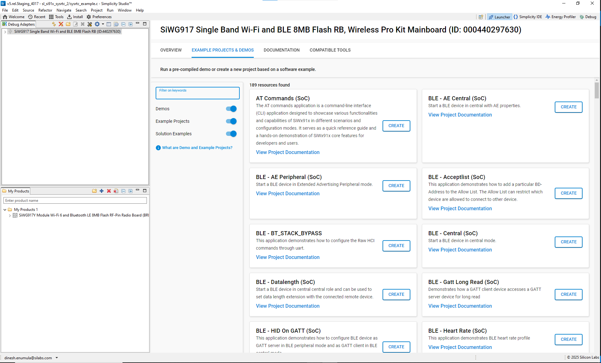
Connect your Si91x radio board. Simplicity Studio automatically detects the board.
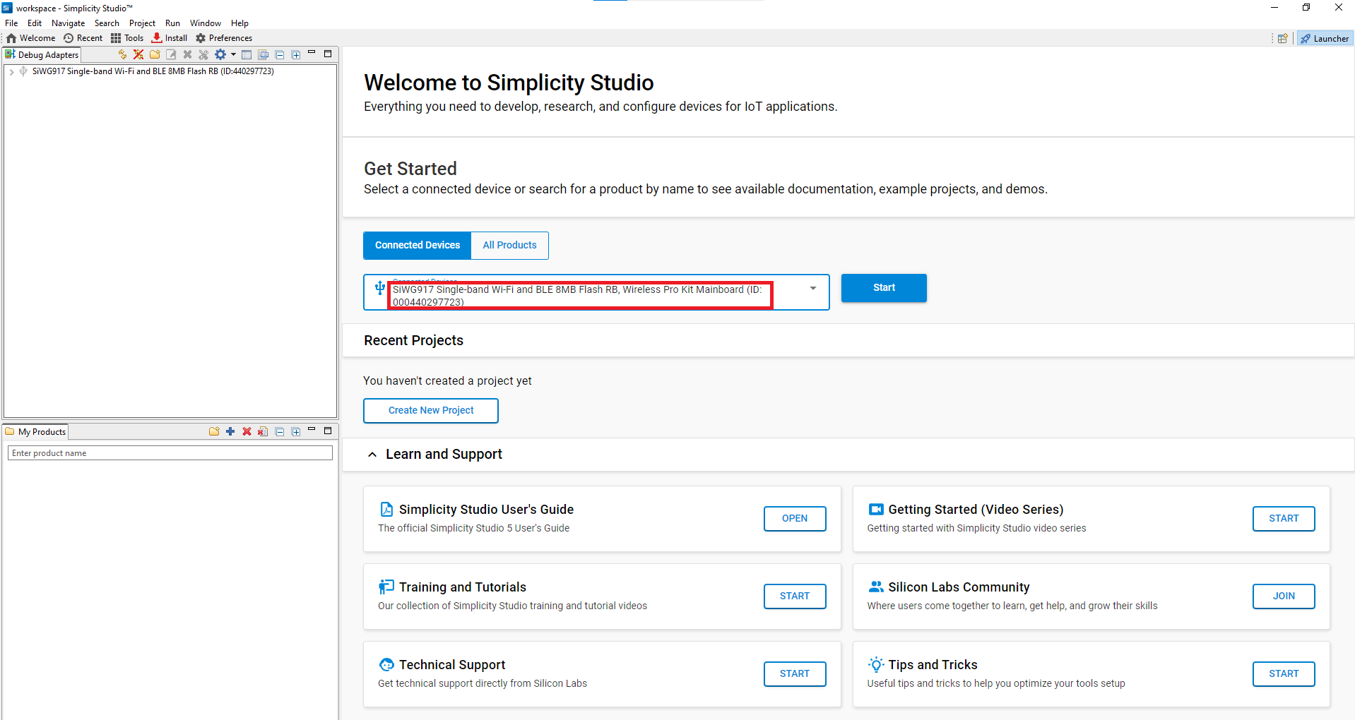
Figure: Board detection in Simplicity StudioFrom Example Projects and Demos, open a SYSRTC example project.
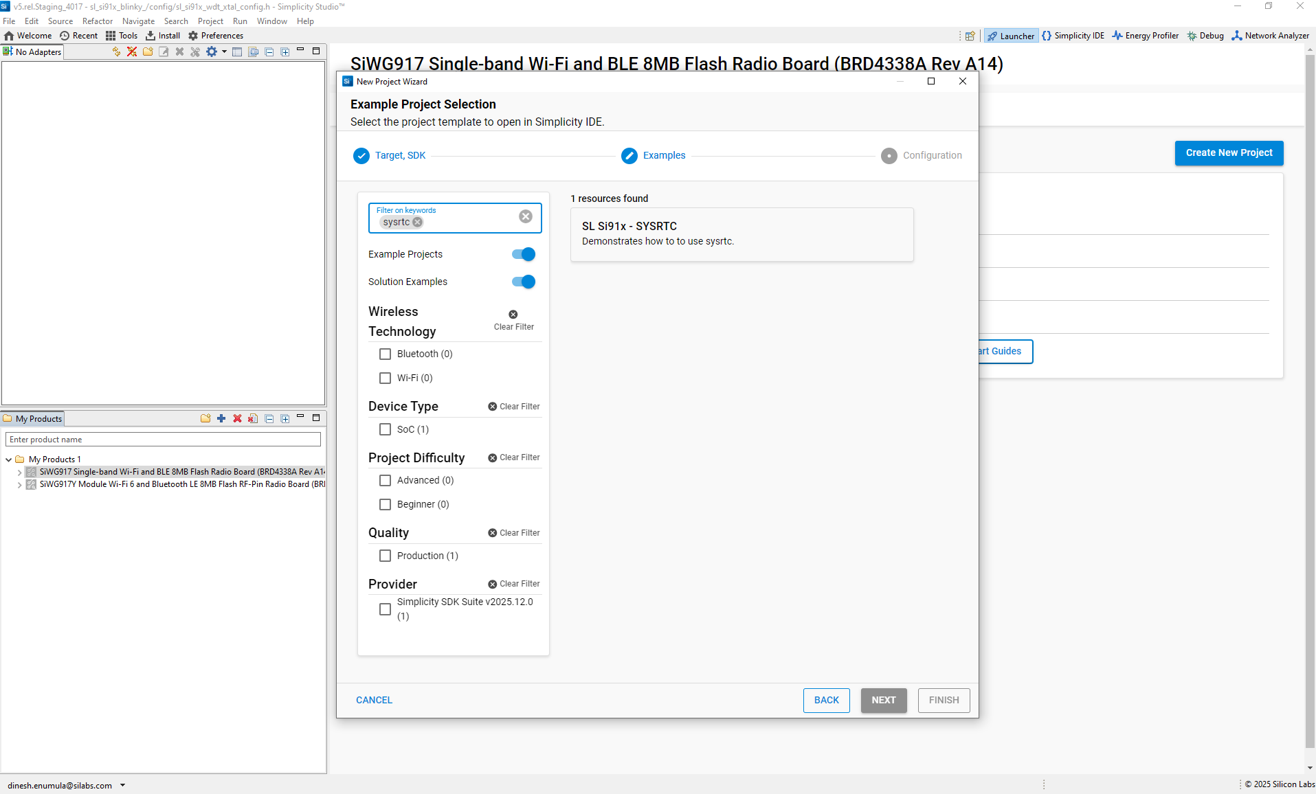
Figure: Selecting a SYSRTC example project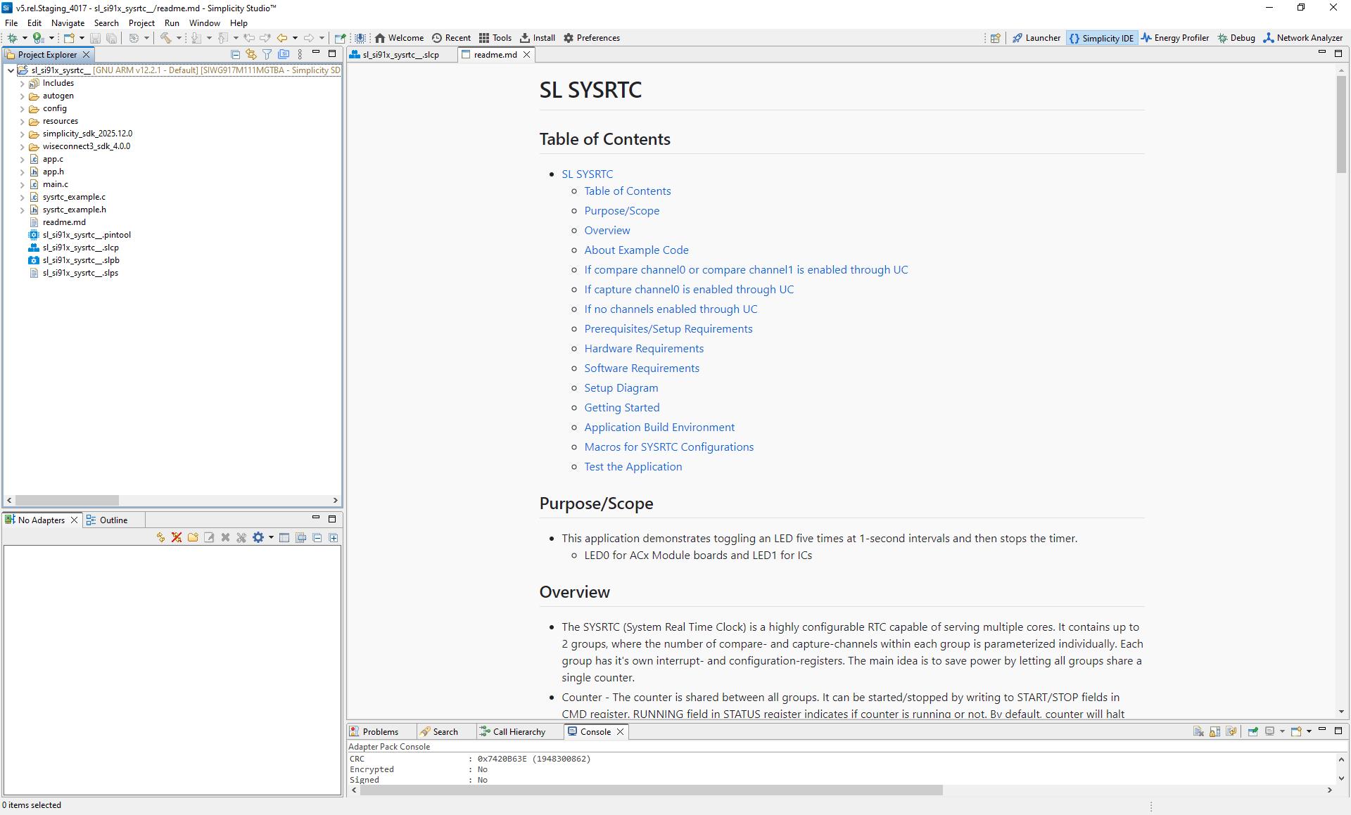
Click Create to add the project to your workspace. Review the project documentation to understand the reference project and its usage.
After project creation, Simplicity Studio generates the following directory structure. Most examples follow this structure and open
readme.mdby default:autogen/: Auto-generated files (configuration headers, linker scripts)config/: Platform-specific configuration headersresources/: Documentation images and resourcessimplicity_sdk_*/: Gecko SDK platform layer and third-party librariesplatform/: Hardware Abstraction Layer (HAL), CMSIS Real-Time Operating System (RTOS), and common librarieswiseconnect3_sdk_*/: WiSeConnect SDK components and resourcesapp.c: Main application source fileapp.h: Main application header filesysrtc_example.c: SYSRTC example source filesysrtc_example.h: SYSRTC example header filemain.c: Application entry pointsl_si91x_sysrtc.slcp: Main project configuration filesl_si91x_sysrtc.pintool: Pin Tool configuration for SYSRTC pinssl_si91x_sysrtc.slps: Project set file for managing solutionsreadme.md: Example documentation and usage instructions
Step 2. Add the SYSRTC Component#
In your project’s
.slcpconfiguration file, go to the Software Components tab.Search for sysrtc and install it if necessary.
Step 3. Configure SYSRTC with Universal Configurator (UC)#
After installation, the Configure option becomes available. Click Configure to set up SYSRTC.
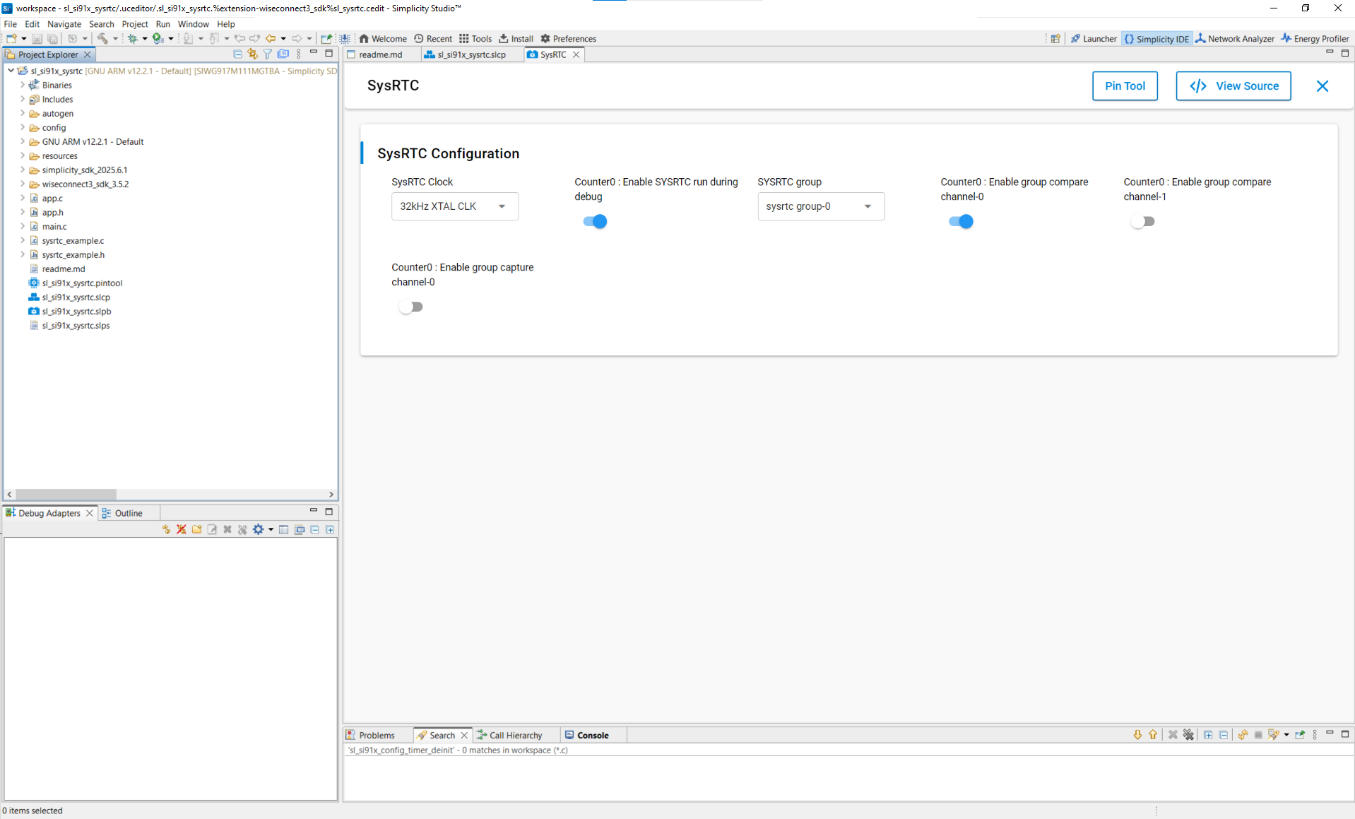
In the UC graphical interface, configure the following:
SYSRTC Clock: Select 32 KHz XTAL clock or 32 KHz RC clock as the source.
Counter0: Enable or disable SYSRTC operation during debug.
SYSRTC Group: Select the SYSRTC group (group-0 or group-1).
Counter0 Options: Enable group compare channels (channel-0, channel-1) and capture channel-0.
Configuration Parameters#
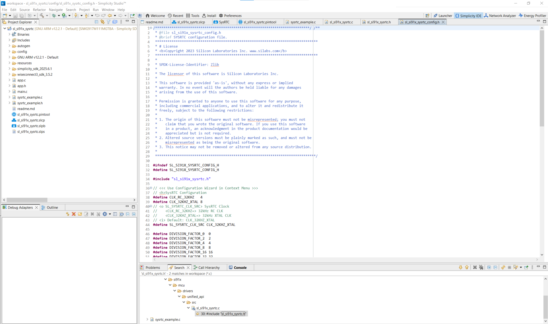
The configuration structure defines available parameters. For a complete list, see the header file: sl_si91x_sysrtc.h.
Step 4. Generate Initialization Code#
When you add or modify SYSRTC components, Simplicity Studio automatically generates the driver and configuration files.
To review them, click View Source in the UC configuration UI.
Step 5. Initialize SYSRTC in Your Application#
Use WiSeConnect SDK APIs to initialize SYSRTC. The driver source and header files are located at:
/wiseconnect3_sdk_<version>/components/device/silabs/si91x/mcu/drivers/unified_api/inc/sl_si91x_sysrtc.h
/wiseconnect3_sdk_<version>/components/device/silabs/si91x/mcu/drivers/unified_api/src/sl_si91x_sysrtc.cThe SYSRTC configuration structure is auto-generated in the autogen folder.
Example initialization code:
// Configure SYSRTC clock source (32 kHz or 1 kHz via divider)
status = sl_si91x_sysrtc_configure_clock(&sl_sysrtc_clk_config_handle);
if (status != SL_STATUS_OK) {
DEBUGOUT("sl_si91x_sysrtc_configure_clock error: %ld\n", (long)status);
return;
}
DEBUGOUT("SYSRTC clock configured\n");
// Initialize and enable SYSRTC (pass pointer to config struct)
status = sl_si91x_sysrtc_init(&sysrtc_handle);
if (status != SL_STATUS_OK) {
DEBUGOUT("sl_si91x_sysrtc_init error: %ld\n", (long)status);
return;
}
DEBUGOUT("SYSRTC initialized\n");
#if (SL_SYSRTC_COMPARE_CHANNEL0_ENABLE == 1) || (SL_SYSRTC_COMPARE_CHANNEL1_ENABLE == 1)
uint32_t compare_value = SYSRTC_COMPARE_VALUE;
// Configure group (enables compare channel(s) per UC)
status = sl_si91x_sysrtc_configure_group(SL_SYSRTC_GROUP, &sysrtc_group_config_handle);
if (status != SL_STATUS_OK) {
DEBUGOUT("sl_si91x_sysrtc_configure_group error: %ld\n", (long)status);
return;
}
DEBUGOUT("SYSRTC group configured\n");
// Register callback and enable interrupts for the selected group
status = sl_si91x_sysrtc_register_callback(sysrtc_callback,
&callback_flag_data,
SL_SYSRTC_GROUP,
&interrupt_enabled);
if (status != SL_STATUS_OK) {
DEBUGOUT("sl_si91x_sysrtc_register_callback error: %ld\n", (long)status);
return;
}
DEBUGOUT("SYSRTC callback registered\n");
// Set counter start value (void API — no status)
sl_si91x_sysrtc_set_count(counter_value1);
// Set compare value and check status
status = sl_si91x_sysrtc_set_compare_value(SL_SYSRTC_GROUP, COMPARE_CHANNEL, compare_value);
if (status != SL_STATUS_OK) {
DEBUGOUT("sl_si91x_sysrtc_set_compare_value error: %ld\n", (long)status);
return;
}
DEBUGOUT("SYSRTC compare set\n");
// Start SYSRTC (void API — no status)
sl_si91x_sysrtc_start();
DEBUGOUT("SYSRTC started\n");
#endif
Step 6. Advanced Configuration Scenarios#
Advanced scenarios extend SYSRTC capabilities for complex use cases.
Multi-group Operation#
Configure both groups with their own timing parameters, then register separate callbacks so you can handle events independently.
// NOTE: Use the group enum names from your SDK header.
// Some drops use SL_SYSRTC_GROUP0 / SL_SYSRTC_GROUP1 (no underscore),
// others use SL_SYSRTC_GROUP_0 / SL_SYSRTC_GROUP_1 (with underscore).
// Replace the identifiers below to match sl_si91x_sysrtc.h in your SDK.
sl_status_t status;
// Configure Group 0
status = sl_si91x_sysrtc_configure_group(SL_SYSRTC_GROUP0 /* or SL_SYSRTC_GROUP_0 */,
&group0_config);
if (status != SL_STATUS_OK) {
DEBUGOUT("Group0 configure error: %ld\n", (long)status);
return;
}
// Configure Group 1
status = sl_si91x_sysrtc_configure_group(SL_SYSRTC_GROUP1 /* or SL_SYSRTC_GROUP_1 */,
&group1_config);
if (status != SL_STATUS_OK) {
DEBUGOUT("Group1 configure error: %ld\n", (long)status);
return;
}
// Enable interrupts + register callbacks for each group
// (Confirm the exact signature in your header: cb, ctx, group, enables_ptr)
sl_sysrtc_interrupt_enables_t int_enable0 = {0};
sl_sysrtc_interrupt_enables_t int_enable1 = {0};
// Example: enable compare interrupts for each group as needed
// int_enable0.compare0 = true; int_enable0.compare1 = true; // if your struct exposes per-source bits
// int_enable1.compare0 = true; // adjust to match your SDK
status = sl_si91x_sysrtc_register_callback(callback_group0,
&flags0 /* user context */,
SL_SYSRTC_GROUP0 /* or _GROUP_0 */,
&int_enable0);
if (status != SL_STATUS_OK) {
DEBUGOUT("Group0 callback register error: %ld\n", (long)status);
return;
}
status = sl_si91x_sysrtc_register_callback(callback_group1,
&flags1 /* user context */,
SL_SYSRTC_GROUP1 /* or _GROUP_1 */,
&int_enable1);
if (status != SL_STATUS_OK) {
DEBUGOUT("Group1 callback register error: %ld\n", (long)status);
return;
}GPIO vs. Register Mode#
The SYSRTC can operate in GPIO mode for external signal interaction or in register mode for internal event handling.
GPIO mode routes capture and compare events to physical pins for observation or triggering, while register mode keeps all operations internal to reduce pin usage and power.
sl_status_t status;
// --- GPIO mode: route SYSRTC signals to external pins ---
status = sl_si91x_sysrtc_enable_input_output_gpio(true);
if (status != SL_STATUS_OK) {
DEBUGOUT("enable_input_output_gpio error: %ld\n", (long)status);
return;
}
// Configure capture input and compare output pins
status = sl_si91x_sysrtc_set_gpio_as_capture_input(SL_SYSRTC_GROUP0 /* or SL_SYSRTC_GROUP_0 */);
if (status != SL_STATUS_OK) {
DEBUGOUT("set_gpio_as_capture_input error: %ld\n", (long)status);
return;
}
status = sl_si91x_sysrtc_set_compare_output_gpio(SL_SYSRTC_GROUP0 /* or SL_SYSRTC_GROUP_0 */,
SL_SYSRTC_CHANNEL0 /* or SL_SYSRTC_CHANNEL_0 */);
if (status != SL_STATUS_OK) {
DEBUGOUT("set_compare_output_gpio error: %ld\n", (long)status);
return;
}
DEBUGOUT("SYSRTC GPIO mode configured\n");
// --- Register mode: internal signal routing only ---
status = sl_si91x_sysrtc_enable_input_output_gpio(false);
if (status != SL_STATUS_OK) {
DEBUGOUT("disable_input_output_gpio error: %ld\n", (long)status);
return;
}
// Use internal capture channel (no external GPIO routing)
status = sl_si91x_sysrtc_sets_register_capture_input(SL_SYSRTC_GROUP0 /* or SL_SYSRTC_GROUP_0 */);
if (status != SL_STATUS_OK) {
DEBUGOUT("sets_register_capture_input error: %ld\n", (long)status);
return;
}
DEBUGOUT("SYSRTC register mode configured\n");Step 7. Build, Flash, and Test#
After you complete configuration, you are ready to build, flash, and test your application to validate SYSRTC functionality.
Step-by-Step: Build, Flash, and Test#
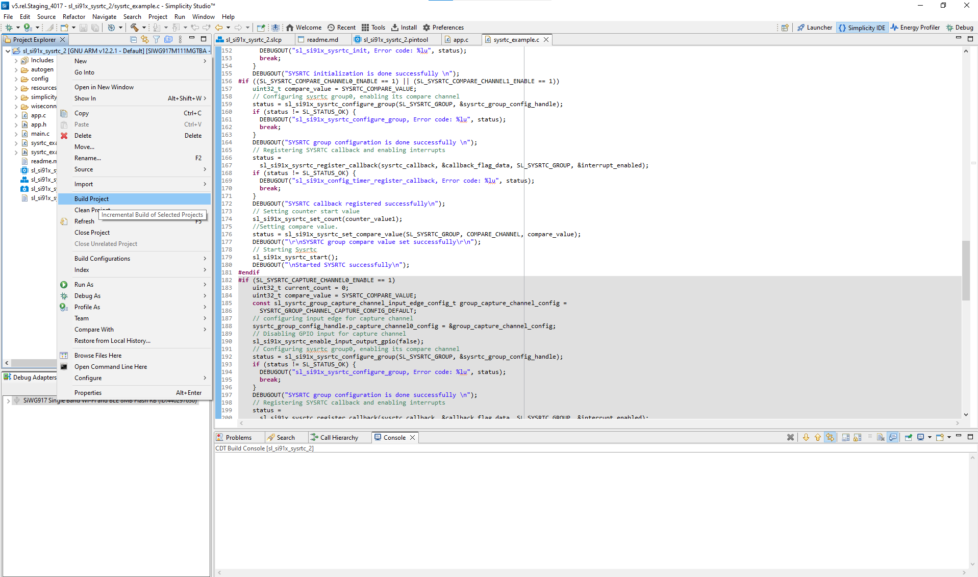
Build your project in Simplicity Studio.
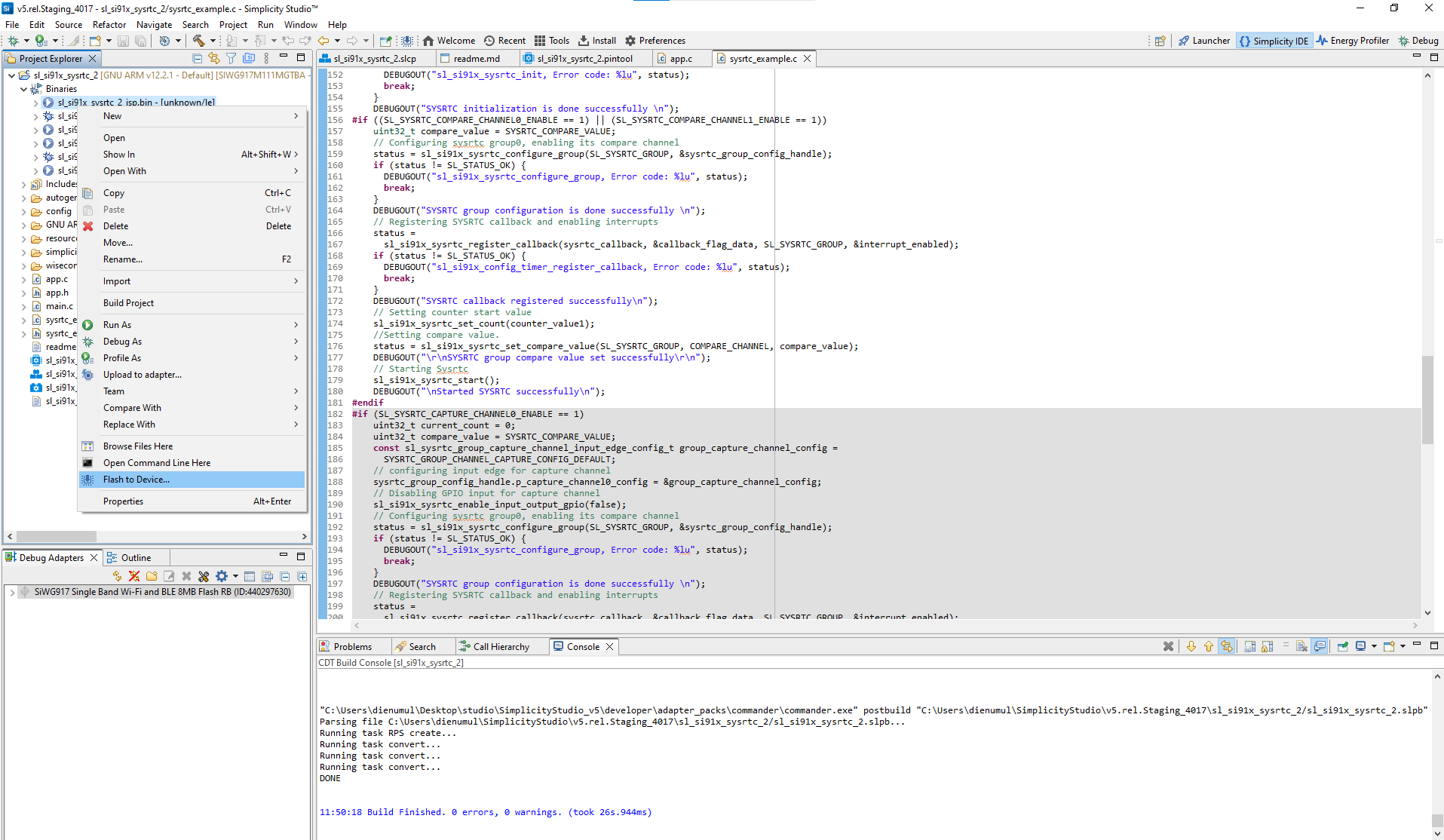
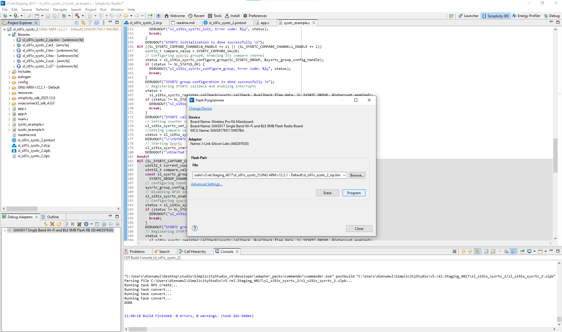
Flash the firmware to your Si91x device.
Verify SYSRTC operation using the serial console or debugger.
Simplicity Studio includes a virtual COM (VCOM) console to view device logs.
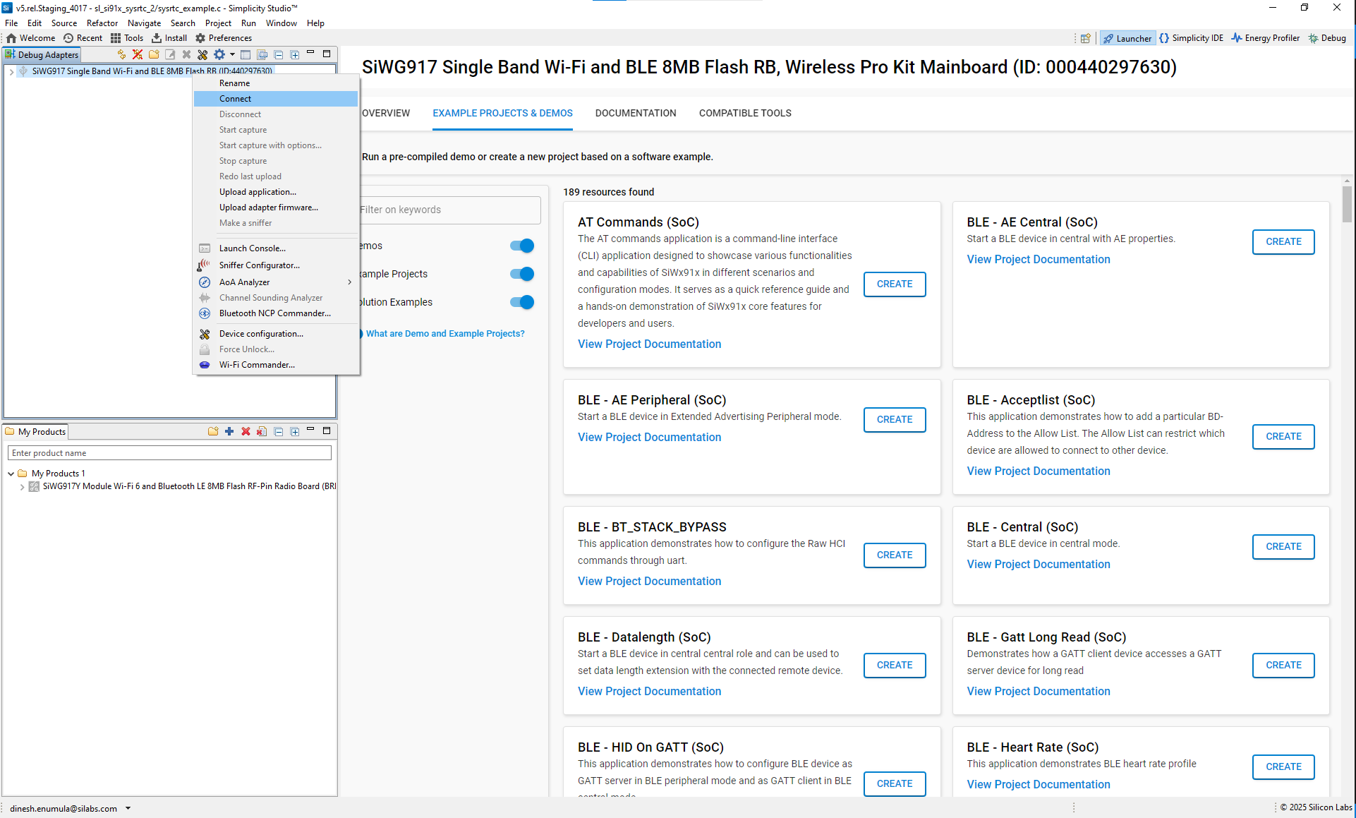
Connected devices view:
Connect devices:
Launch console:
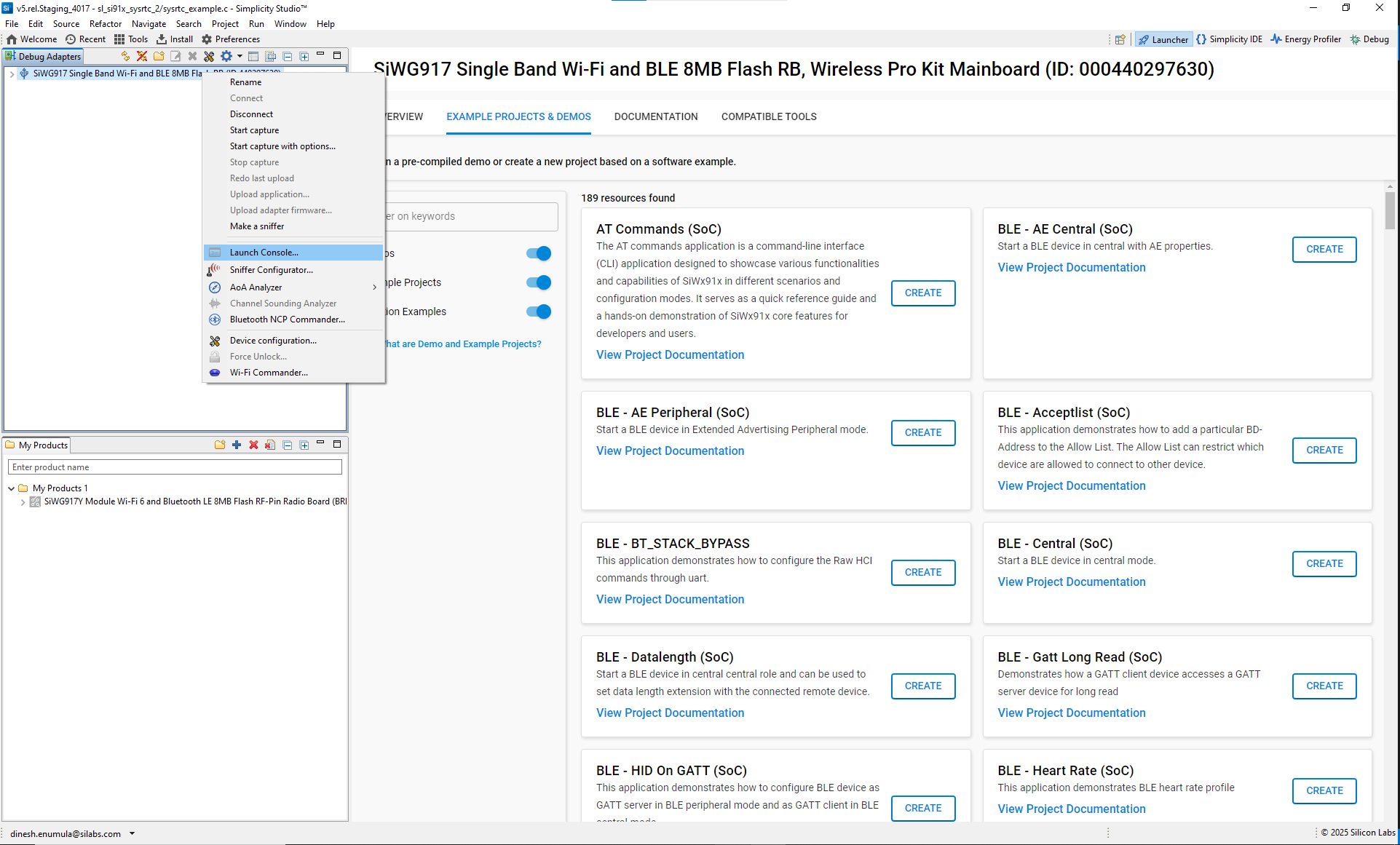
View console settings:
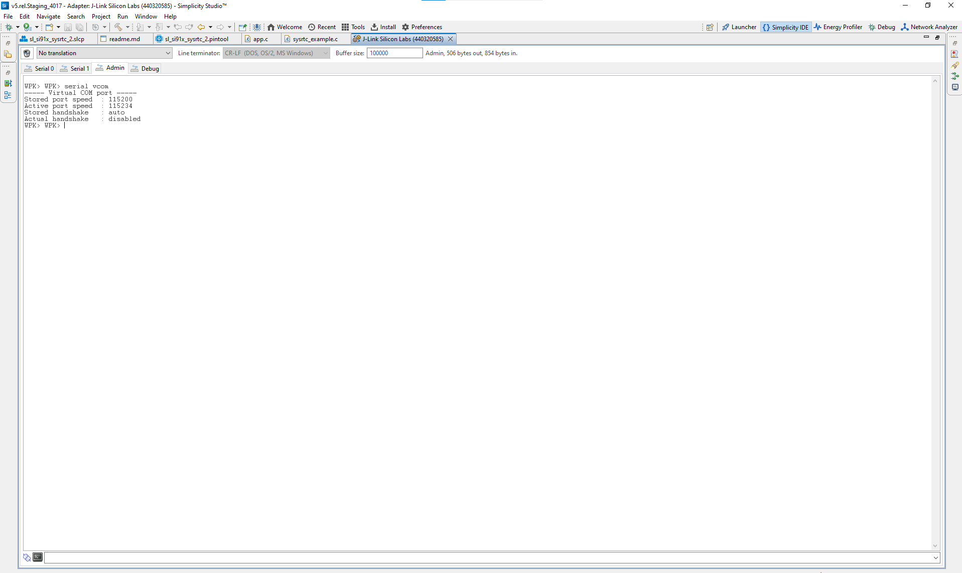
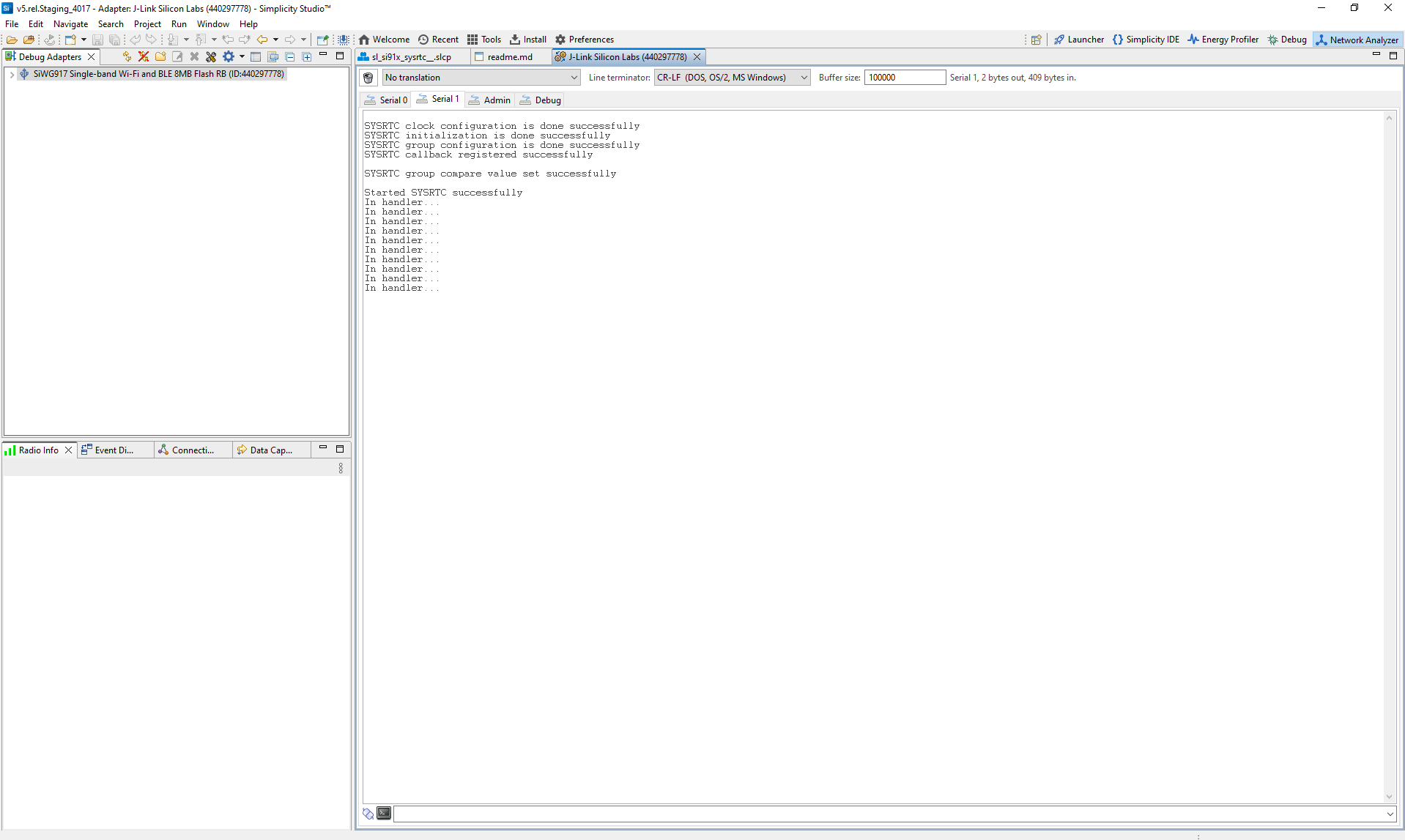
How to view logs:
Open the console and select the
serial1tab.Place your cursor in the text entry field.
Press Enter to wake up the console.
SYSRTC log example:
Tip: You can also use third-party terminal programs such as Tera Term or PuTTY.
References#
Related Example Projects
SL Si91x – SYSRTC