Getting Started with WiSeConnect™ SDK v3.x in SoC Mode#
This guide describes how to get started with developing an application for SiWx91x™ using the WiSeConnect™ SDK v3.x in System-on-chip (SoC) mode, where both the application and the networking stack run on the SiWx917 chipset.
Check Prerequisites#
Hardware#
SiWx917 SoC development kit
Windows/Linux/MacOS computer with a USB port
USB cable
For boards other than BRD4338A:
USB-to-TTL converter
Jumper cables
Software#
Simplicity Studio
GSDK version 4.3.1 or later
For boards other than BRD4338A:
Serial Debug Assistant
Note: We recommend using the latest GSDK version.
Install Simplicity Studio#
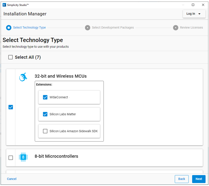
Download the latest version of Simplicity Studio and follow the installation instructions. During the installation:
make sure you log in to Simplicity Studio in the Installation Manager window,
select Install by technology type, and
select the WiSeConnect extension under 32-bit and Wireless MCUs.
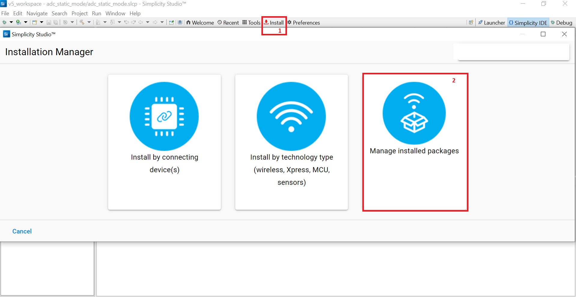
To install Early Access packages, select Install > Manage installed packages from the Simplicity Studio home page.
Note: To request Early Access permission, contact the Silicon Labs Sales team by clicking here.
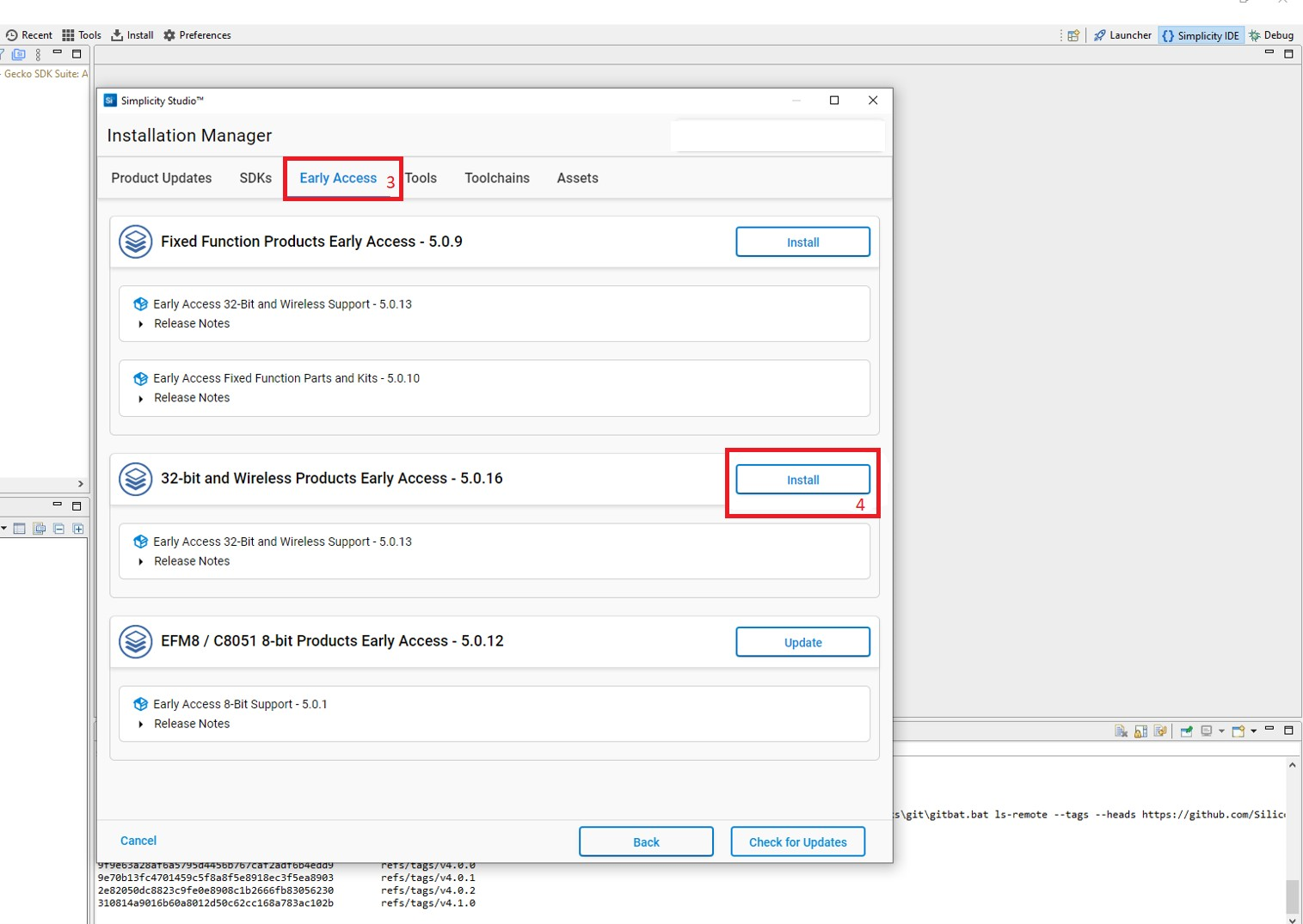
Select Early Access > 32-bit and Wireless Product Early Access-x.x.xxx and click Install.
Note: If you already installed Early Access packages, you may see an option to Update the packages. Click Update.
Connect SiWx91x to Computer#
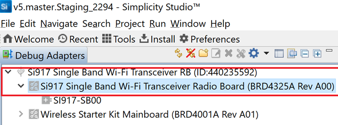
Connect your SiWx91x Wireless Starter Kit (WSTK) board to your computer using a USB cable.
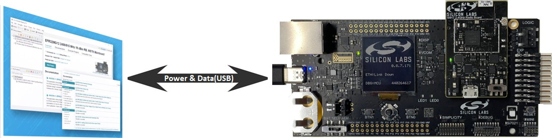
Simplicity Studio will detect and display your radio board.
Troubleshoot a Board Detection Failure#
If Simplicity Studio does not detect your radio board, try the following:
Request access to and install the Early Access packages if not already done. See step 2 in the Install Simplicity Studio section.
In the Debug Adapters pane, Click the Refresh button (having an icon of two looping arrows).
Press the RESET button on the radio board.
Power-cycle your device by disconnecting and reconnecting the USB cable.
Install the WiSeConnect 3 Extension#
If you already selected the WiSeConnect - 3.x.x extension while Install Studio, you may skip this section.
Before installing the WiSeConnect 3 extension, upgrade to a compatible GSDK version if not already done. See the Prerequisites section for the supported GSDK versions.
You may install WiSeConnect 3 through one of the following alternative paths:
Installation Manager (recommended)
Install WiSeConnect 3 through the Installation Manager#
Log in to Simplicity Studio if not already done.
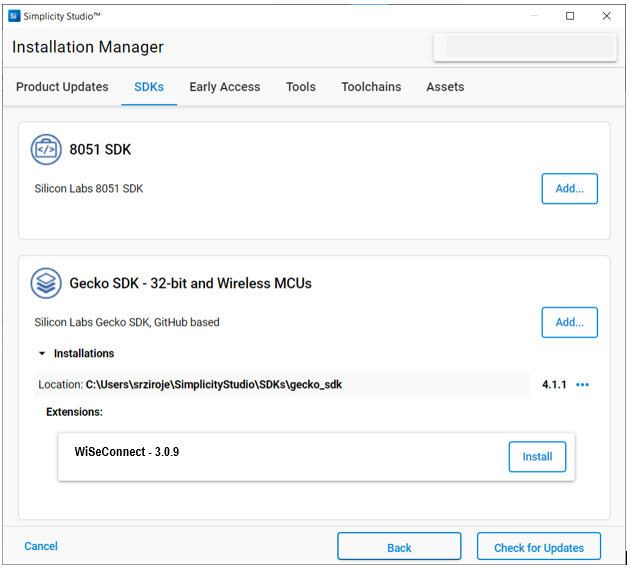
In the Simplicity Studio home page, select Install > Manage installed packages.
Select the SDKs tab.
Next to the WiSeConnect - 3.x.x extension, click Install.
Install WiSeConnect 3 through the Manage SDKs Window#
Download the WiSeConnect v3.x source code from the following URL after substituting 3.x.x with the desired release version:
https://github.com/SiliconLabs/wiseconnect/archive/refs/tags/v3.x.x.zipIf you don't know your release version, go to the GitHub Releases Page and select the version to download.
Unzip the downloaded
wiseconnect-3.x.x.zipfile. It will be extracted into a folder structure similar to the following:wiseconnect-3.x.x |--- wiseconnect-3.x.x |------ <source code>Launch Simplicity Studio and log in.
In the Debug Adapters pane, select your radio board.
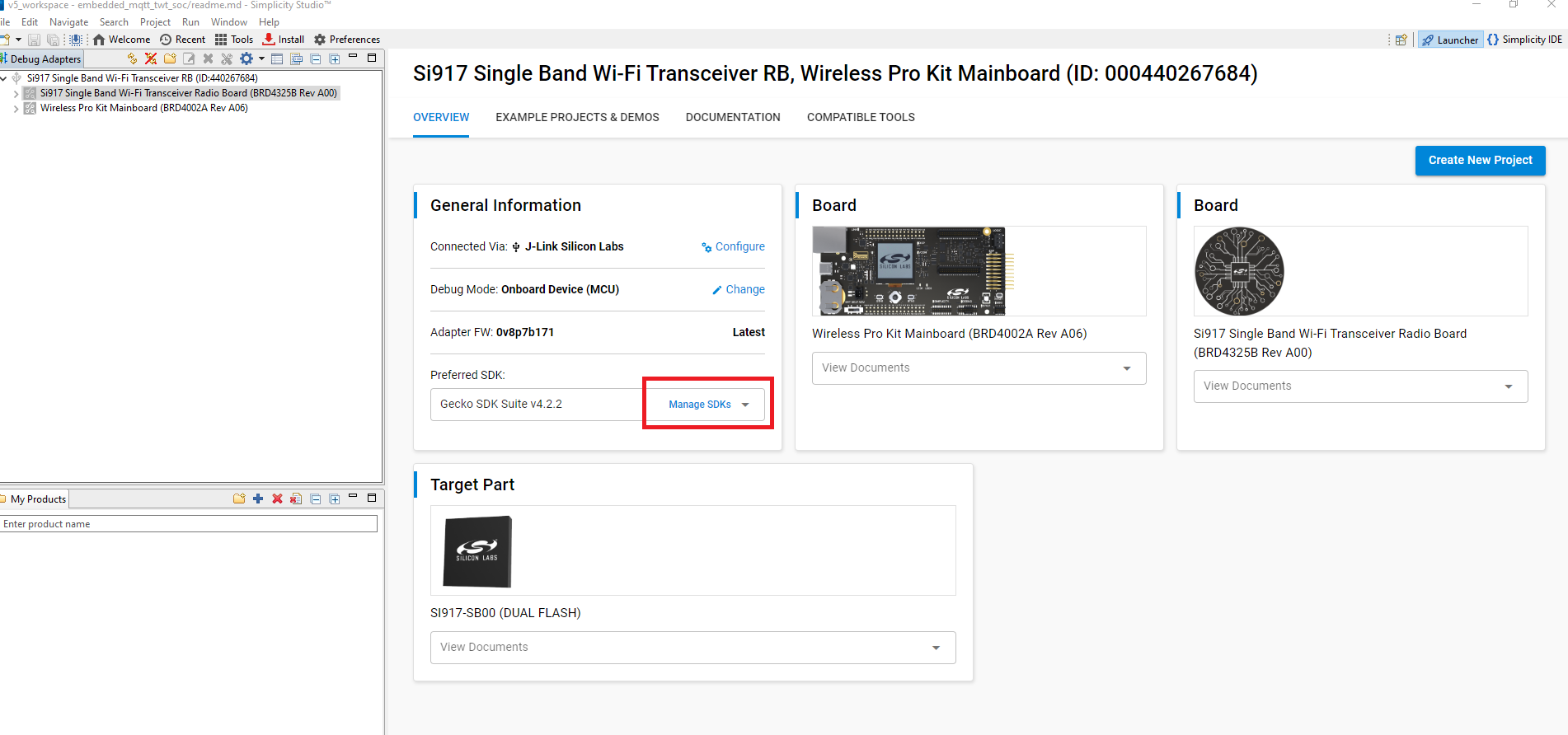
In the General Information section, click Manage SDKs.
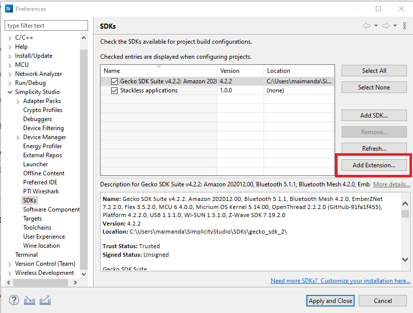
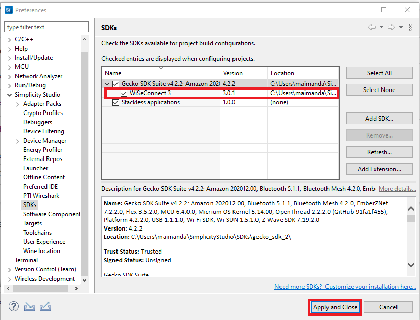
The Preferences window will be opened in the SDKs section.
Select Gecko SDK Suite vx.x.x and click Add Extension.
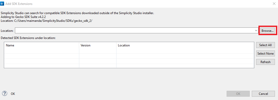
In the Add SDK Extensions window, click Browse.
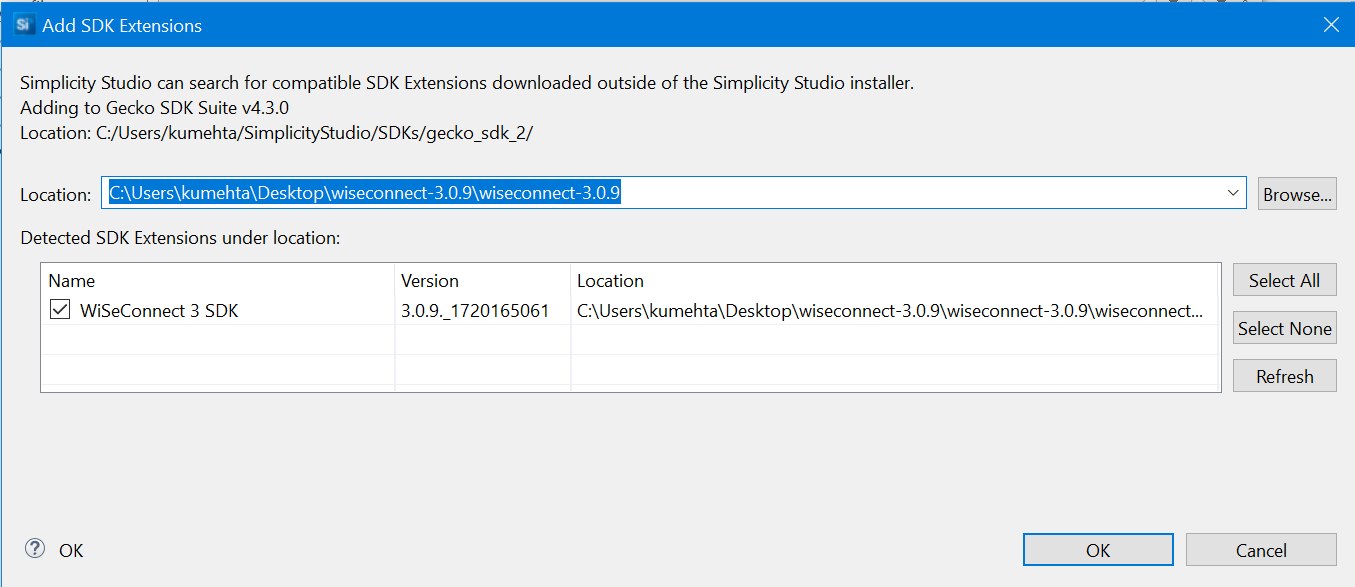
Locate and select the
wiseconnect-3.x.xsub-folder extracted in step 2 above which contains the source code.Studio will detect the WiSeConnect 3 SDK extension.
Select the detected extension and click OK.
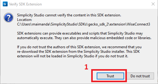
If a Verify SDK Extension popup is displayed, click Trust.
The selected WiSeConnect 3 extension will be displayed.
Click Apply and Close.
Upgrade SiWx91x Connectivity Firmware#
We recommend that you upgrade the SiWx917 connectivity firmware to the latest available version when:
you first receive an SiWx917 evaluation kit (EVK)
you first receive a radio board, or
you upgrade to a new version of the WiSeConnect 3 extension
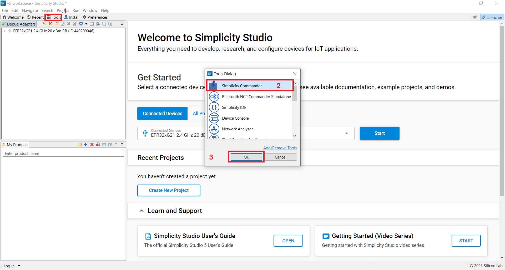
In the Simplicity Studio home page, click Tools.
In the Tools dialog, select Simplicity Commander and click OK.
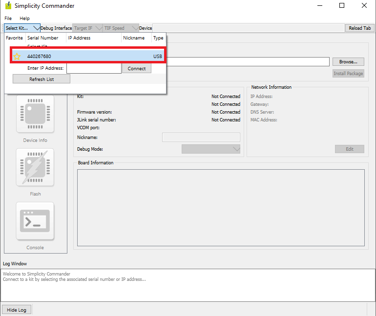
In the Simplicity Commander window, click Select Kit and choose your radio board.
In the navigation pane, go to the Flash section.
Click Browse next to the Binary File field.
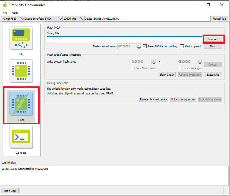
Locate and select the firmware file to flash from within the
connectivity_firmwaresub-folder of the WiSeConnect 3 extension path.Note:
If you don't see any files in the sub-folder, select All files in the file filter field in the Browse dialog.
The WiSeConnect 3 extension path is the one where the extension was downloaded during installation. If you're not sure what the path is, you may refer to the location in the Preferences > SDKs page shown on clicking Manage SDKs.
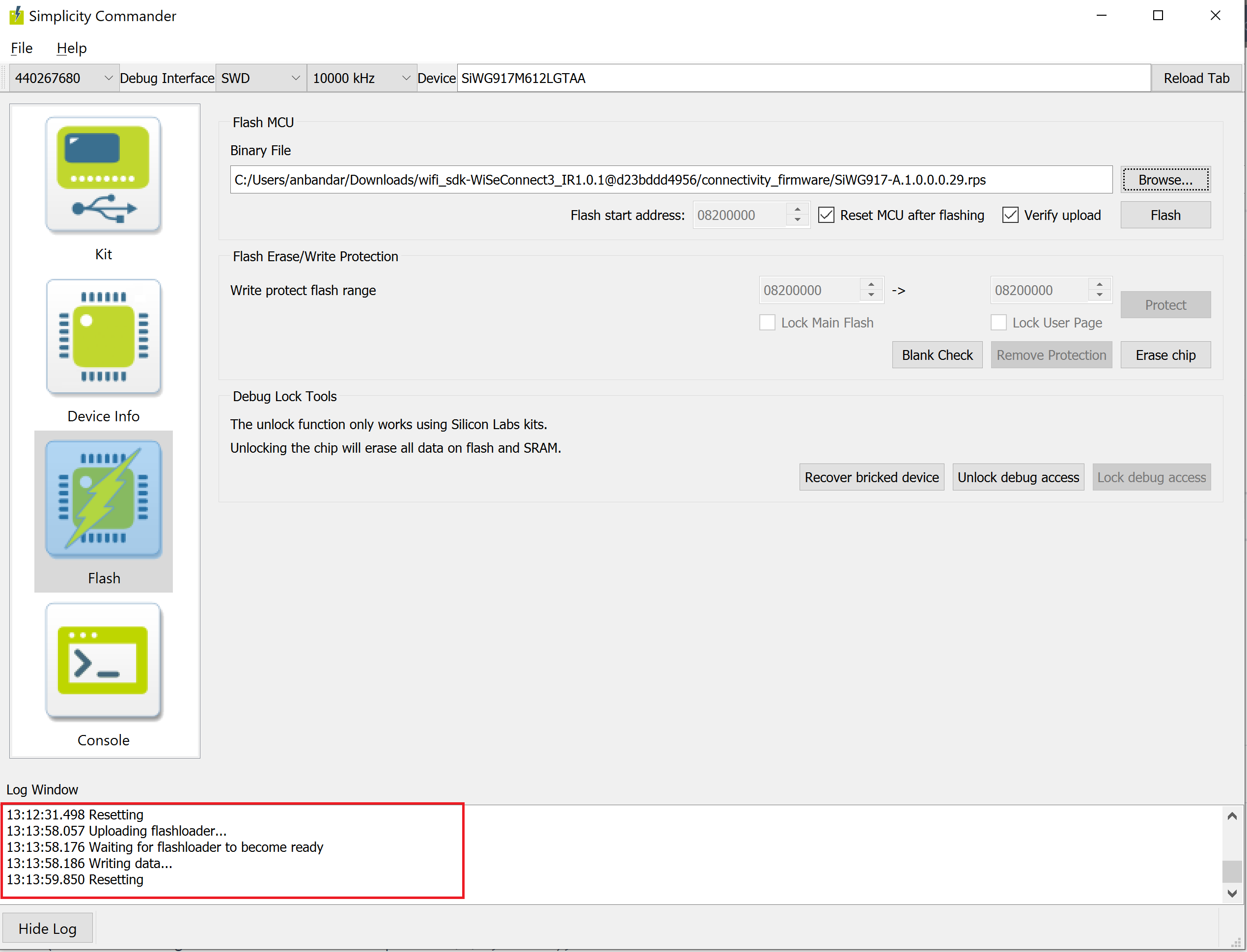
Click Flash.
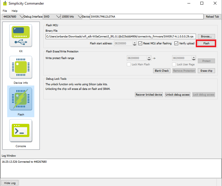
The firmware will be flashed and the Log Window will display a "Resetting" message.
Troubleshoot Firmware Update Failure#
If the firmware update fails, try the following:
Toggle the power switch towards AEM (Advanced Energy Monitoring) on the WSTK board.
Perform the following steps and try the firmware update again
Toggle the ISP switch towards ISP on the radio board.
Press the RESET button on the WSTK board.
Toggle the ISP switch away from ISP on the radio board.
In the Flash section in step 5 above, click Erase chip.
The flash will be erased.
Retry the firmware upgrade.
Create Project#
Log in to Simplicity Studio and connect the SiWx91x to your computer.
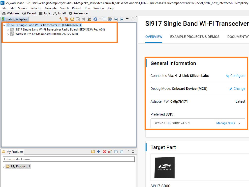
Go to the Debug Adapters section.
Select your radio board from the displayed list.
The Launcher page will display the selected radio board's details.
Select the OVERVIEW tab.
Verify the following in the General Information section:
The Debug Mode is Onboard Device (MCU).
The Preferred SDK is the version you selected earlier.
Select the EXAMPLE PROJECTS AND DEMOS tab.
Locate the example you want and click CREATE.
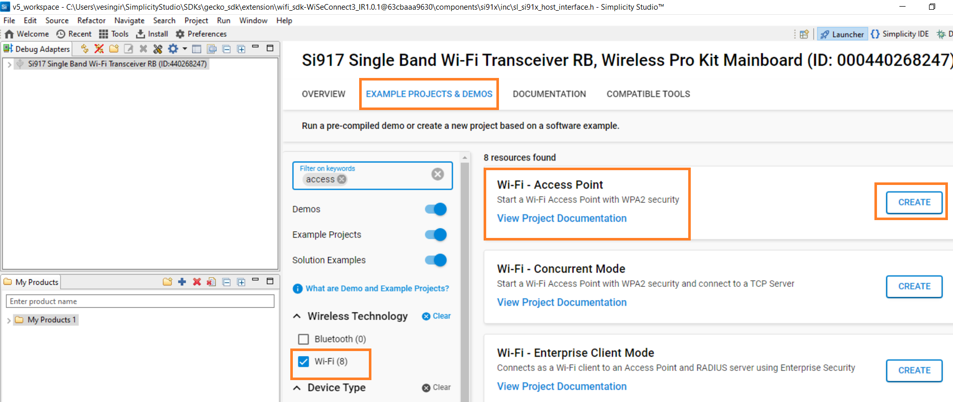
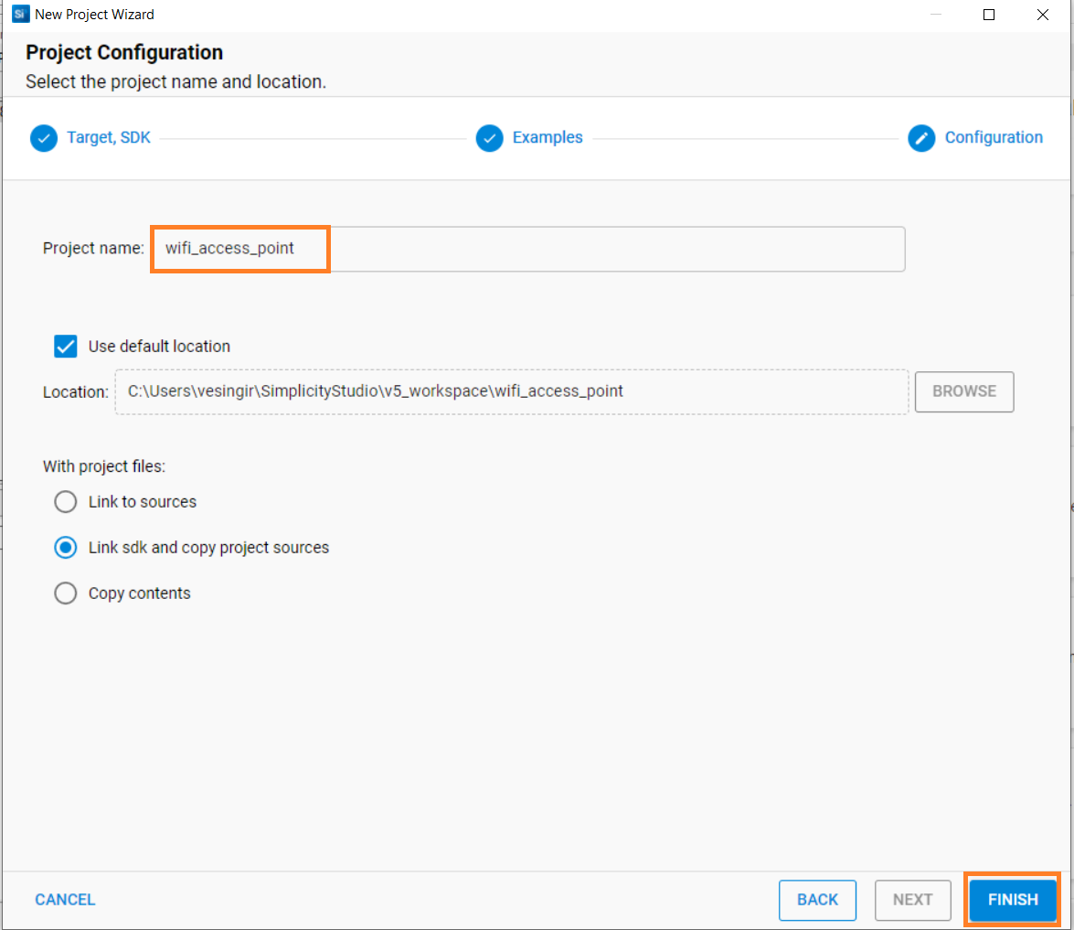
In the New Project Wizard window, click Finish.
Note: The Copy contents option is not currently supported.
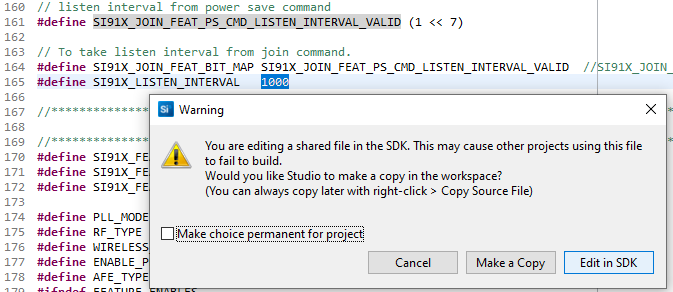
Note: The Make a Copy option is not currently supported while editing a shared SDK file, when prompted to either make a copy of the file or edit it in the SDK itself.
Build an Application#
Launch Simplicity Studio and log in.
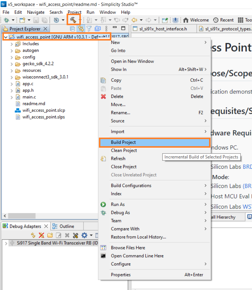
In the Project Explorer pane, right-click the project name and select Build Project.
You may also click the Build button with a hammer icon on the Simplicity IDE perspective toolbar.
Flash an Application#
There are two alternative methods to flash an application to the application processor of the SiWx91x device:
Flash an Application Built Using Simplicity Studio#
Build the application as described in the Build an Application section.
In the Project Explorer pane, right-click on your project name and select Run As > 1 Silicon Labs ARM Program.
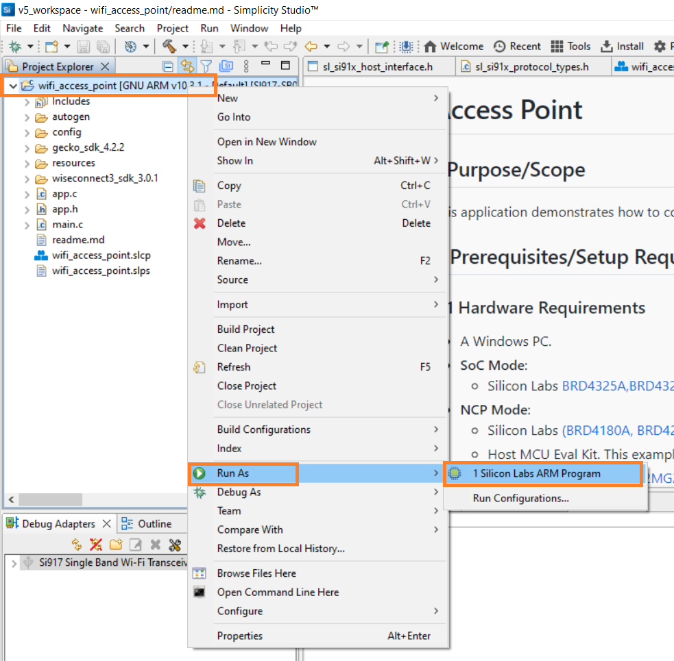
The application binary will be flashed on the radio board and the application will start running.
View the standard output or enter input data as needed. See the Console Input and Output section.
Flash an Application Binary#
If the binary was built as described in the Build an Application section, a file with a
.rpsextension is generated. This file will be available under GNU ARM vXX.x.x - Default in the users workspace. To see its location, right-click on the.rpsfile and select Show In > System Explorer.Alternatively, you may have obtained a
.rpsfile through another means such as someone else building and providing the binary to you.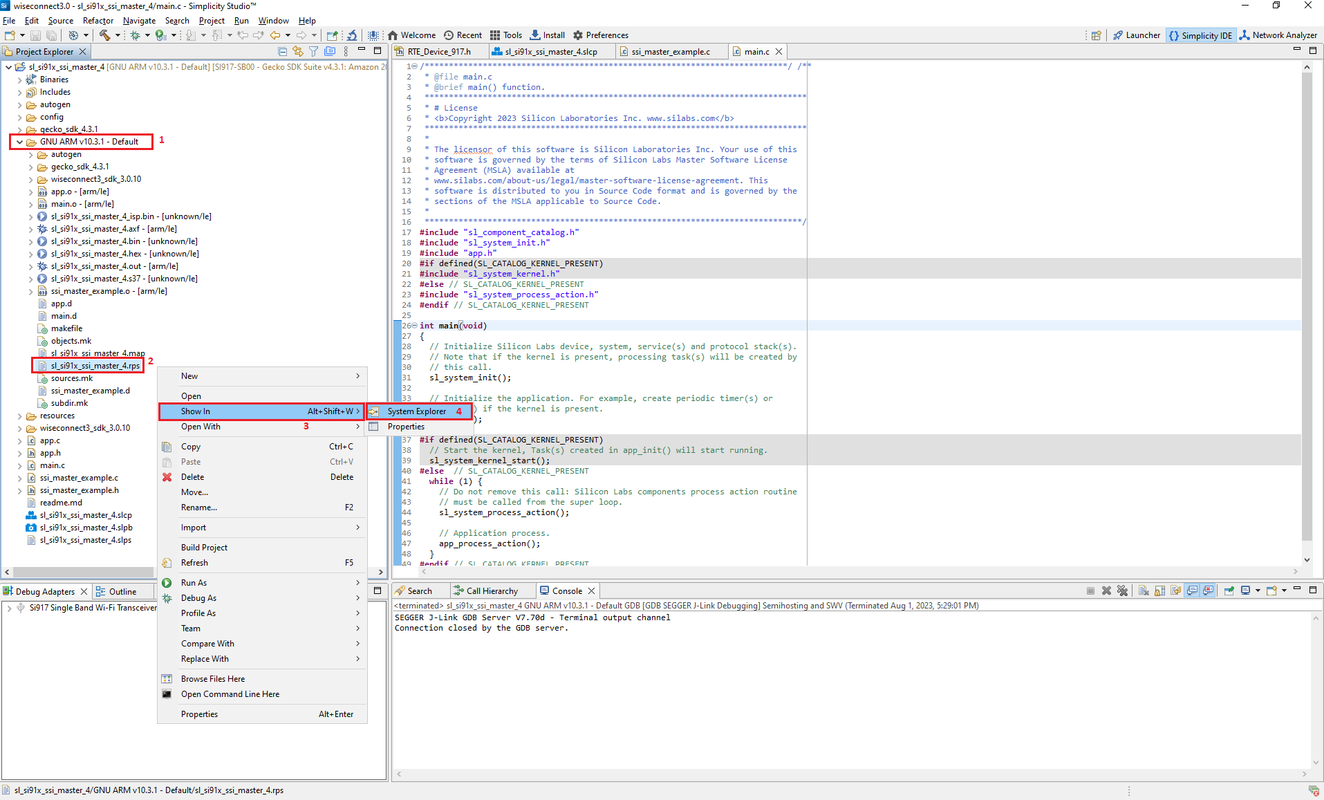
Follow the instructions in the Flashing the SiWx91x Connectivity Firmware section to flash the application binary. Instead of choosing the SiWx91x firmware file, select the
.rpsyou want to flash.Note: If you don't see
.rpsfiles in the sub-folder, select All files in the file filter field in the Browse dialog.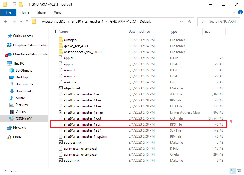
Troubleshoot an Application Flash Failure#
The application may fail to flash if Studio failed to detect your radio board. See the Troubleshooting for Board Detection Failure section.
Configure the Debugger#
Note: Application debugging currently does not work. This is a known issue and has two alternative workarounds:
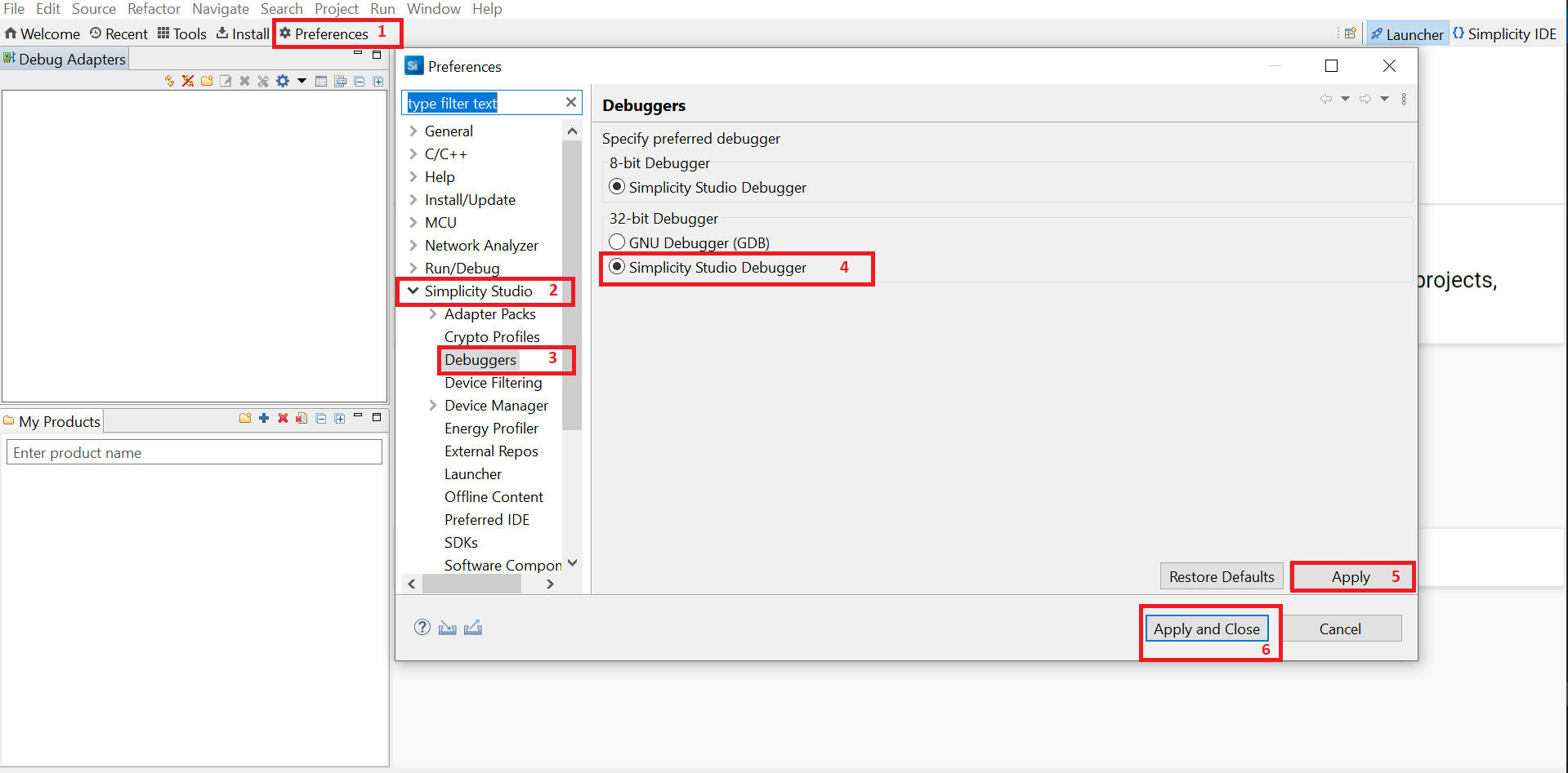
Configure the Simplicity Studio Debugger#
Open Simplicity Studio.
Click Preferences.
In the Preferences window, select Simplicity Studio > Debuggers.
Select Simplicity Studio Debugger and click Apply.
Click Apply and Close.
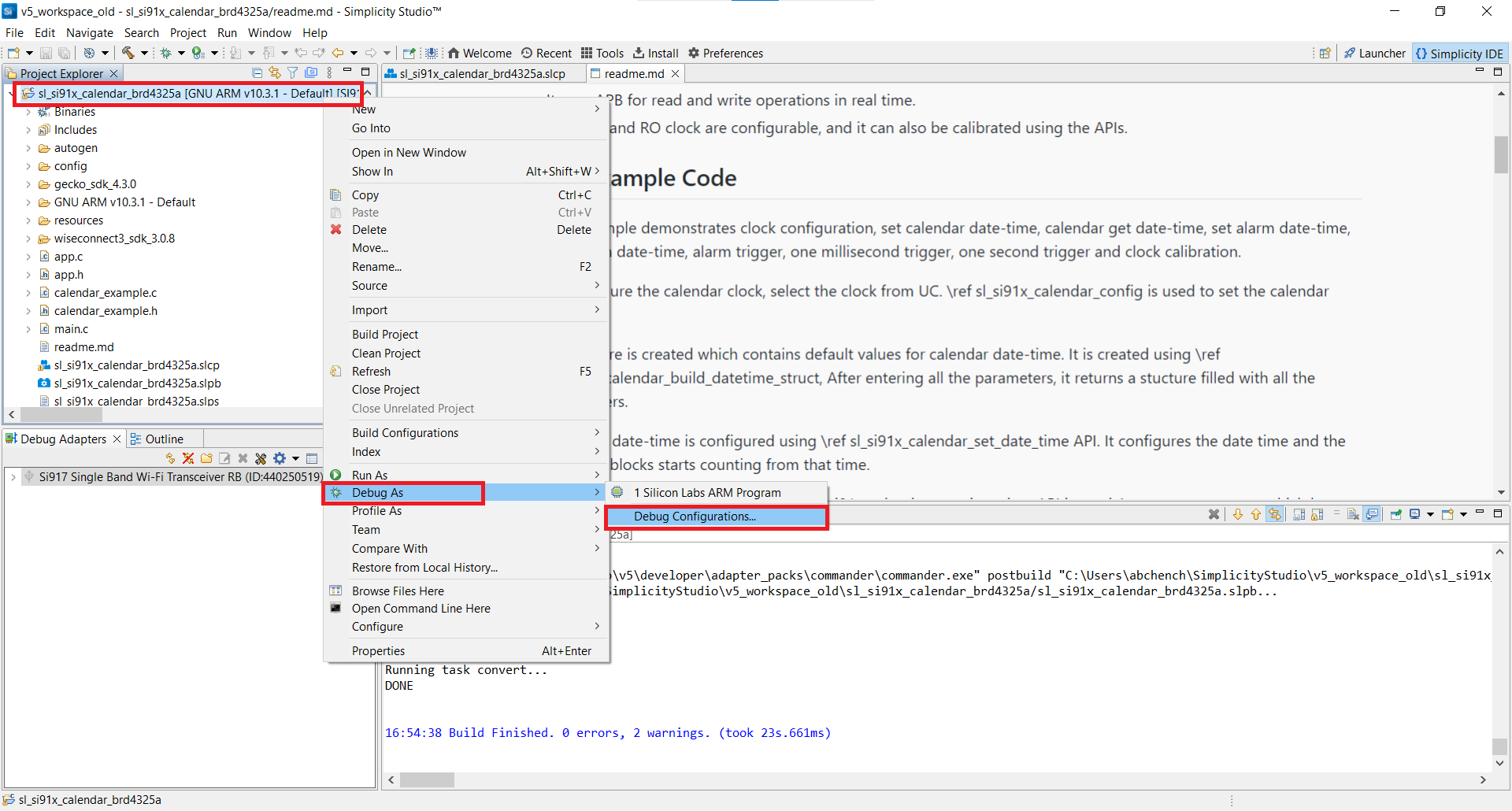
Configure the GDB Debugger#
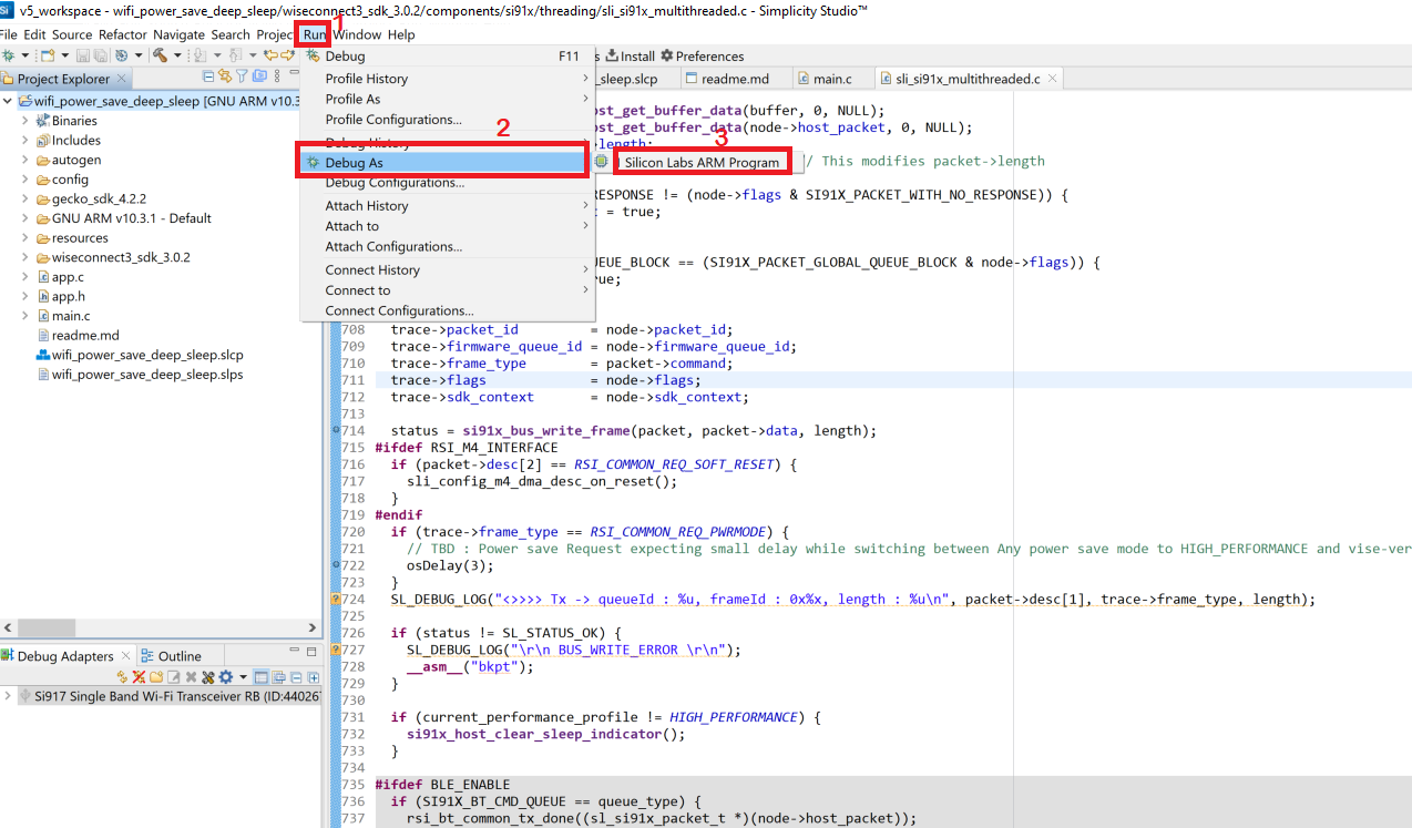
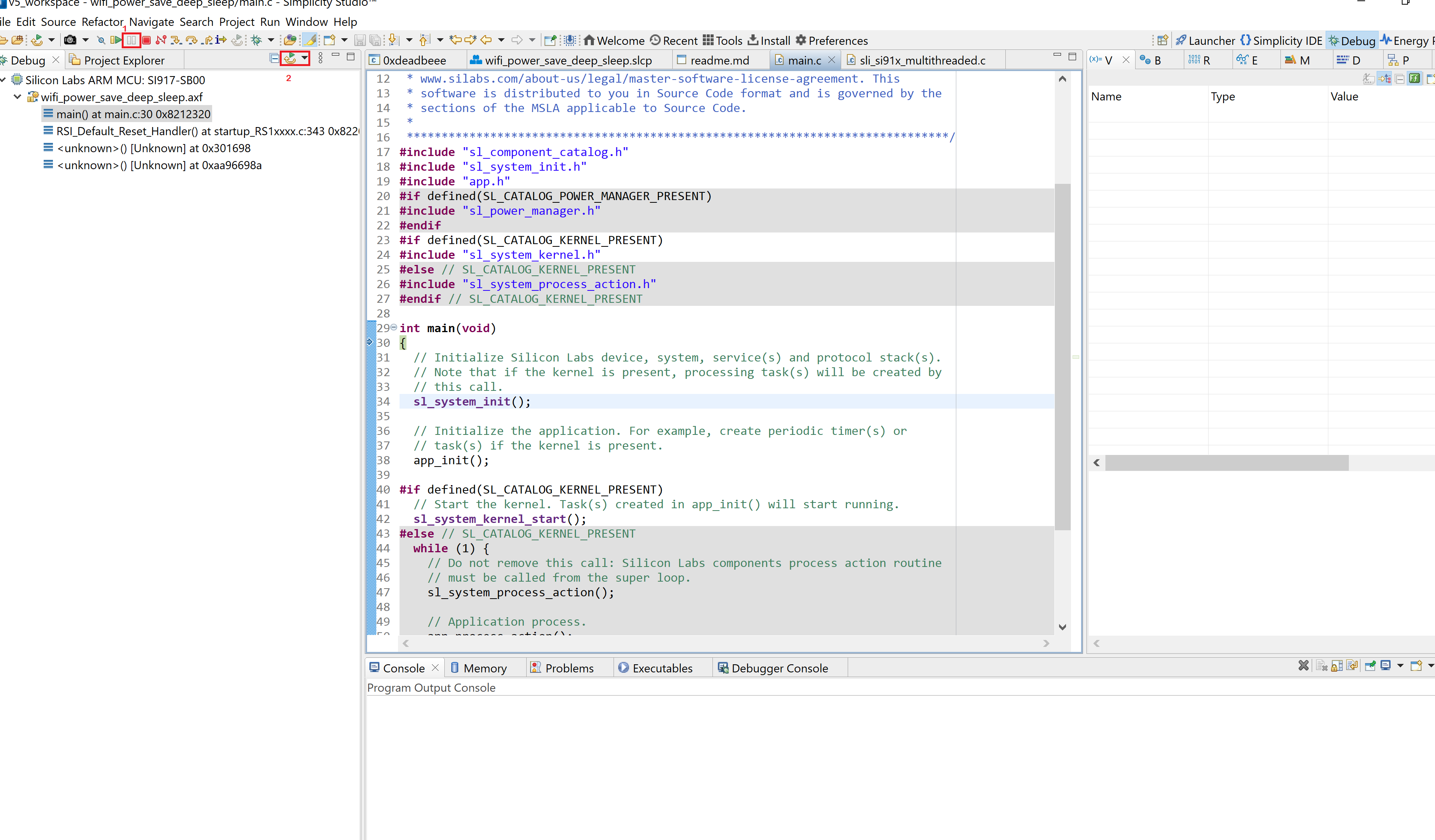
In the Project Explorer pane, right-click on your project name and select Debug As > 1 Silicon Labs ARM Program.
Studio will switch to debug mode and fail to halt execution at
main()as described in the debugging section.Close the Debug pane.
In the Project Explorer pane, right-click on your project name and select Debug As > Debug Configurations.
Under GDB SEGGER J-Link Debugging, select your project name.
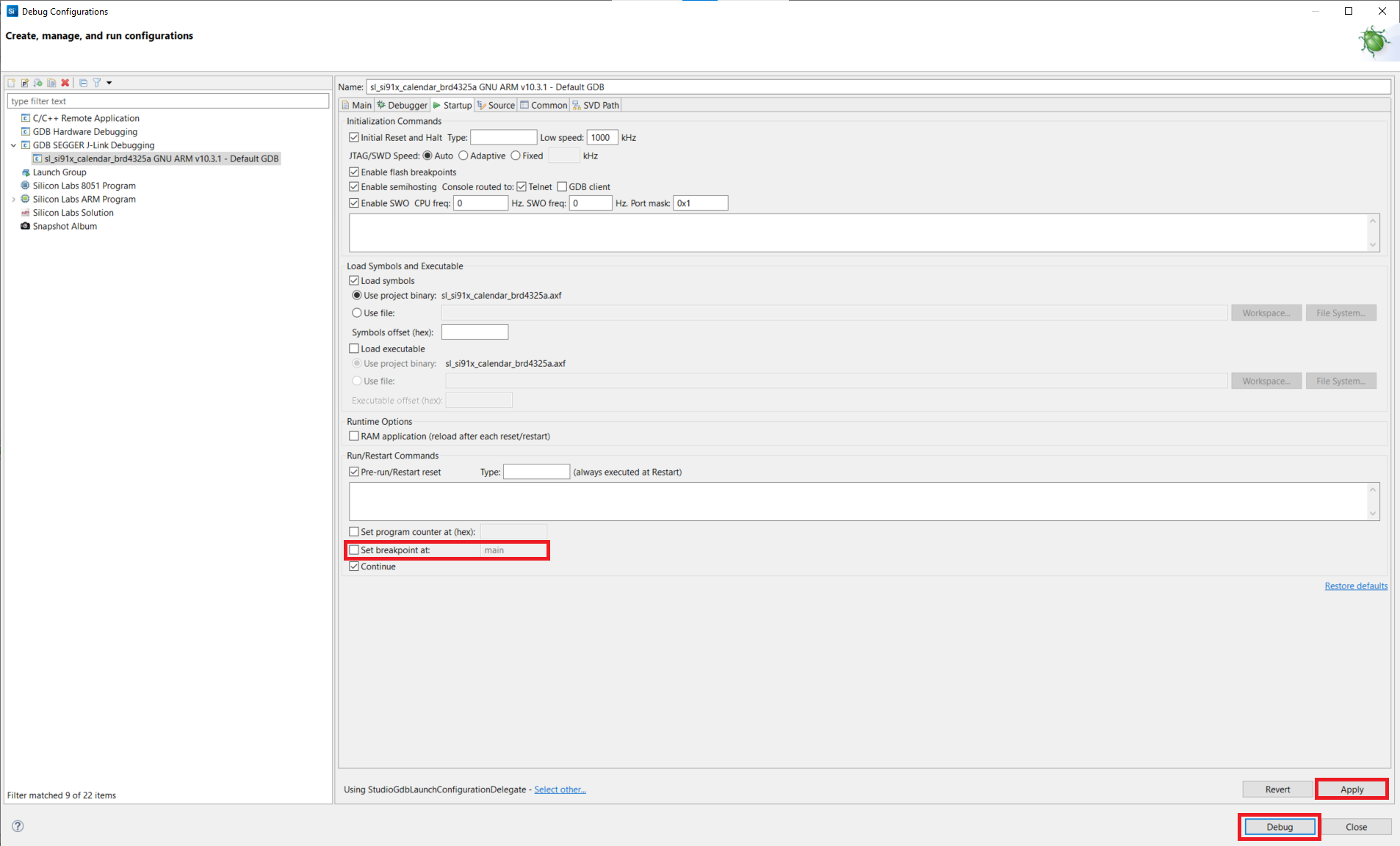
Select the Startup tab.
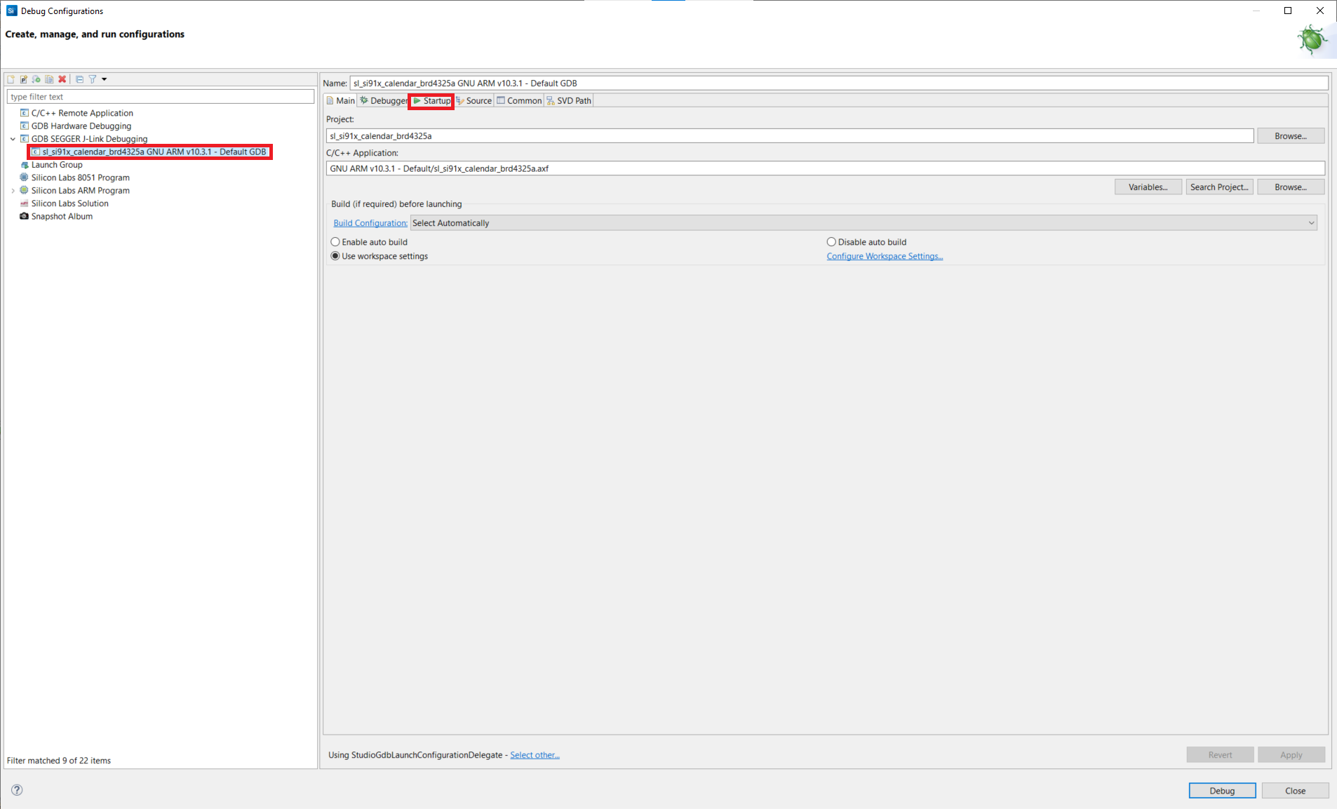
Unselect the Set breakpoint at field.
Click Apply and click Debug.
Debug an Application#
In the Project Explorer pane, select your project name.
From the menu, select Run > Debug As > 1 Silicon Labs ARM Program.
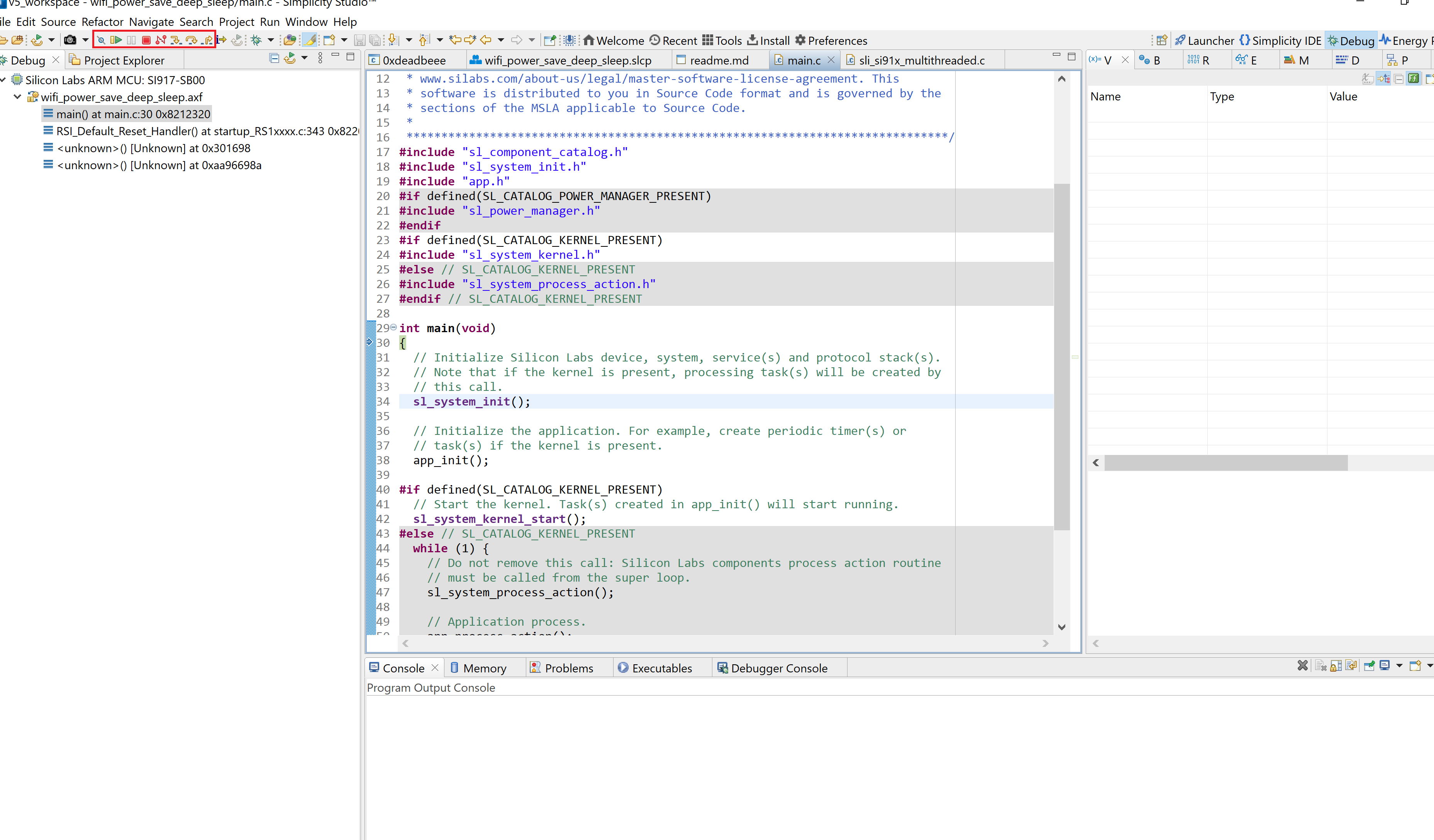
Studio will switch to debug mode and halt execution at the
main()function in your application.Add a break point in the desired location of the code and click the Resume button (having an icon with a rectangular bar and play button).
Execution will halt at the break point.
Use the following debug functions to direct the execution of the code:
Step In button (having an icon with a arrow pointing between two dots).
Step Over button (having an icon with an arrow going over a dot).
Step Out button (having an icon with an arrow pointing out from between two dots).
View the standard output or enter input data as needed. See the Console Input and Output section.
Troubleshoot an Application Debug Failure#
The application may fail to enter the debug mode due to one of the following reasons:
Studio failed to detect your radio board. See the Troubleshooting for Board Detection Failure section.
Studio failed to halt execution at the
main()function. Try the following steps:Click the Suspend button (having a pause button icon).
Click the Reset button (having an icon of a play button with an arrow underneath).
Unknown reason - try re-launching Simplicity Studio.
Console Input and Output#
Note: The SiWx91x radio boards do not currently support VCOM. This support is coming soon. In the meantime:
If you are using BRD4338A, console output and input can be performed after upgrading the WSTK firmware.
If you are using a board other than BRD4338A:
Console output (such as logs) from the device can be seen by performing a WSTK firmware upgrade.
Console input (such as commands) can be sent to the device using a USB-to-TTL Converter.
Perform Console Output and Input for BRD4338A#
Note: If you are using the BRD4338A radio board, the WSTK firmware is not available in Simplicity Studio and must be flashed by following the steps below. This firmware will be available in a future release. For other boards, see the sections that follow for console output and console input.
Connect your WSTK board to your computer.
Open Simplicity Studio.
In the Debug Adapters pane, select your WSTK board.
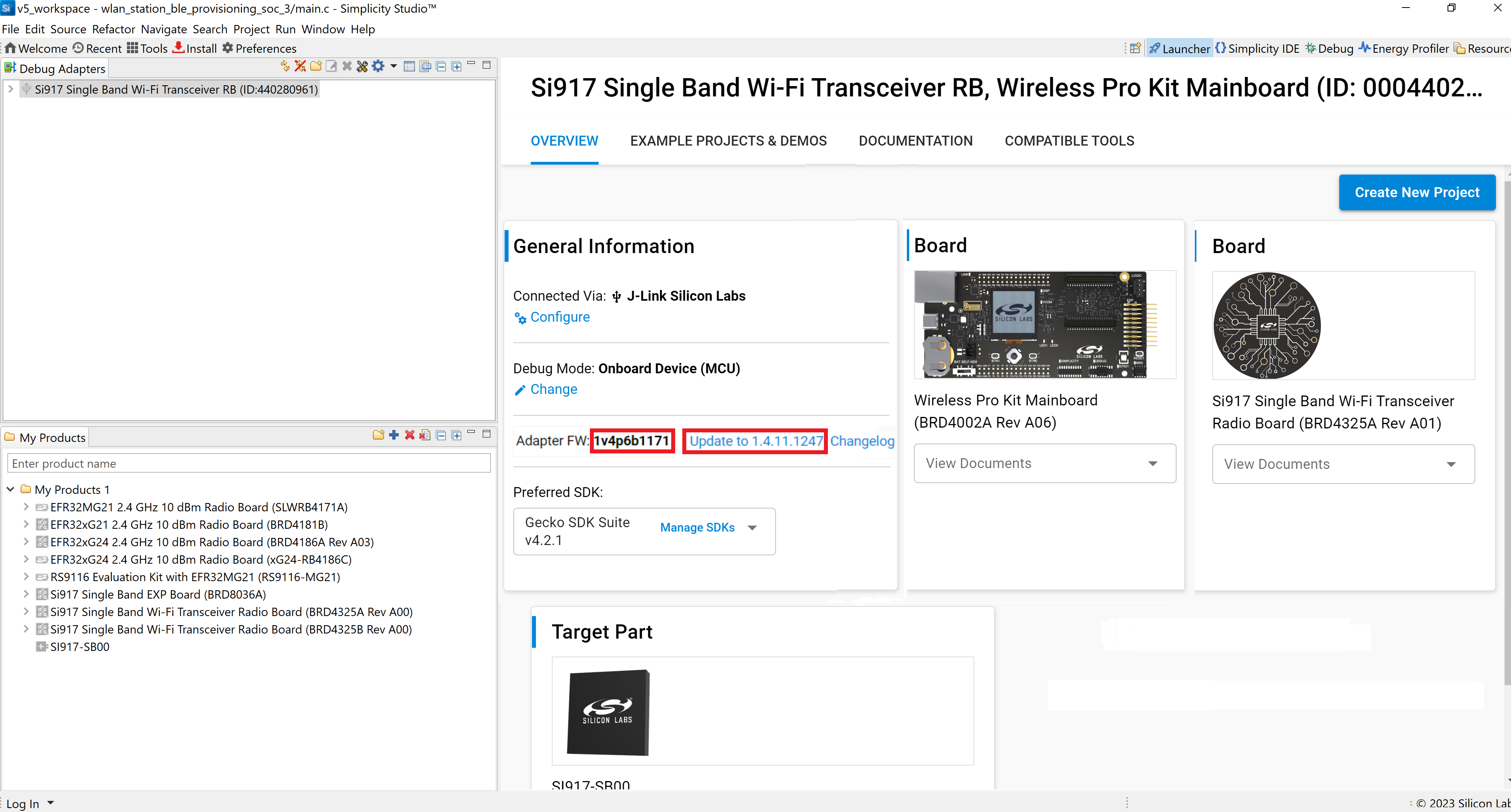
The Adapter FW field shows your WSTK board's current firmware version, similar to 1vnpxxbyyy, where n is the major version, xx is the patch version number and yyy is the build number.
Click Update to 1.4.xx.yyyy if the version is before 1v4p10b215, or in other words:
Major version = 4 and one of the following is true:
patch < 10 or
patch = 10 and build < 215
The firmware will be upgraded on your WSTK board.
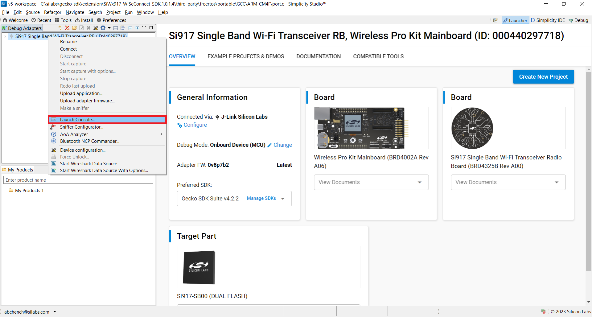
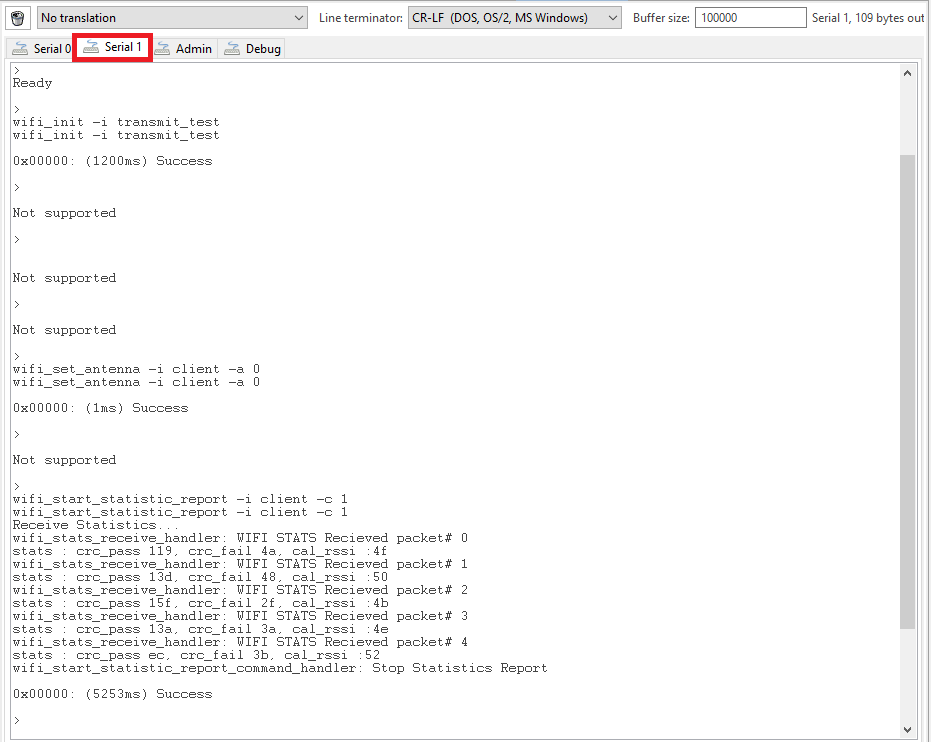
In the Debug Adapters pane, right-click on your radio board and click Launch Console.
Select the Serial 1 tab.
Place the cursor inside the text input field and hit Enter.
Console output will start getting displayed in the Serial 1 tab.
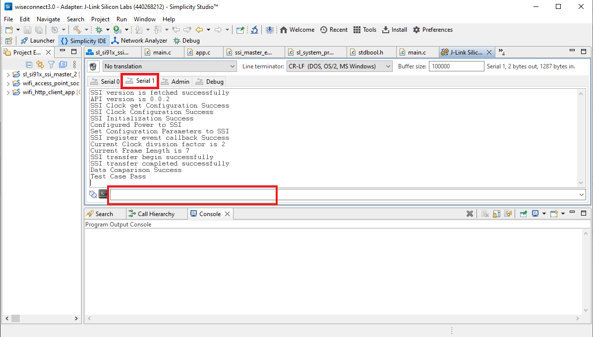
Console input can be entered and sent to the device.
View the Console Output for Other Boards#
If you are using BRD4338A, please follow the instructions in the Console Output and Input for BRD4338A section for viewing console output. Otherwise, follow the steps here.
Connect your WSTK board to your computer.
Open Simplicity Studio.
In the Debug Adapters pane, select your WSTK board.
The Adapter FW field shows your WSTK board's current firmware version, similar to 1vnpxxbyyyy, where n is the major version, xx is the patch version number and yyy is the build number.
Click Update to 1.4.xx.yyyy if the version is before 1v4p10b..., or in other words, major version = 4 and patch < 10.
The firmware will be upgraded on your WSTK board.
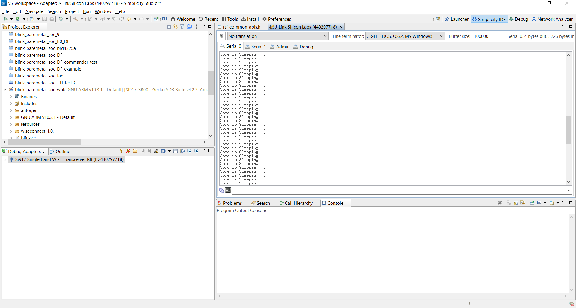
In the Debug Adapters pane, right-click on your radio board and click Launch Console.
Select the Admin tab and press Enter to see the
WPK>prompt.Enter the following command to set the Baud Rate:
pti config 0 vuart 115200
Select the Serial 0 tab to view the console output from the running application.
Enter the Console Input for Other Boards#
If you are using BRD4338A, please follow the instructions in the Console Output and Input for BRD4338A section for entering console input. Otherwise, follow the steps here.
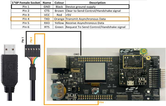
Connect the TXD pin (pin 4) of the USB-to-TTL Converter to pin 14 on the WSTK board.
Connect the GND pin (pin 1) of the USB-to-TTL Converter to pin 1 on the WSTK board.
Press the RESET button on the WSTK board.
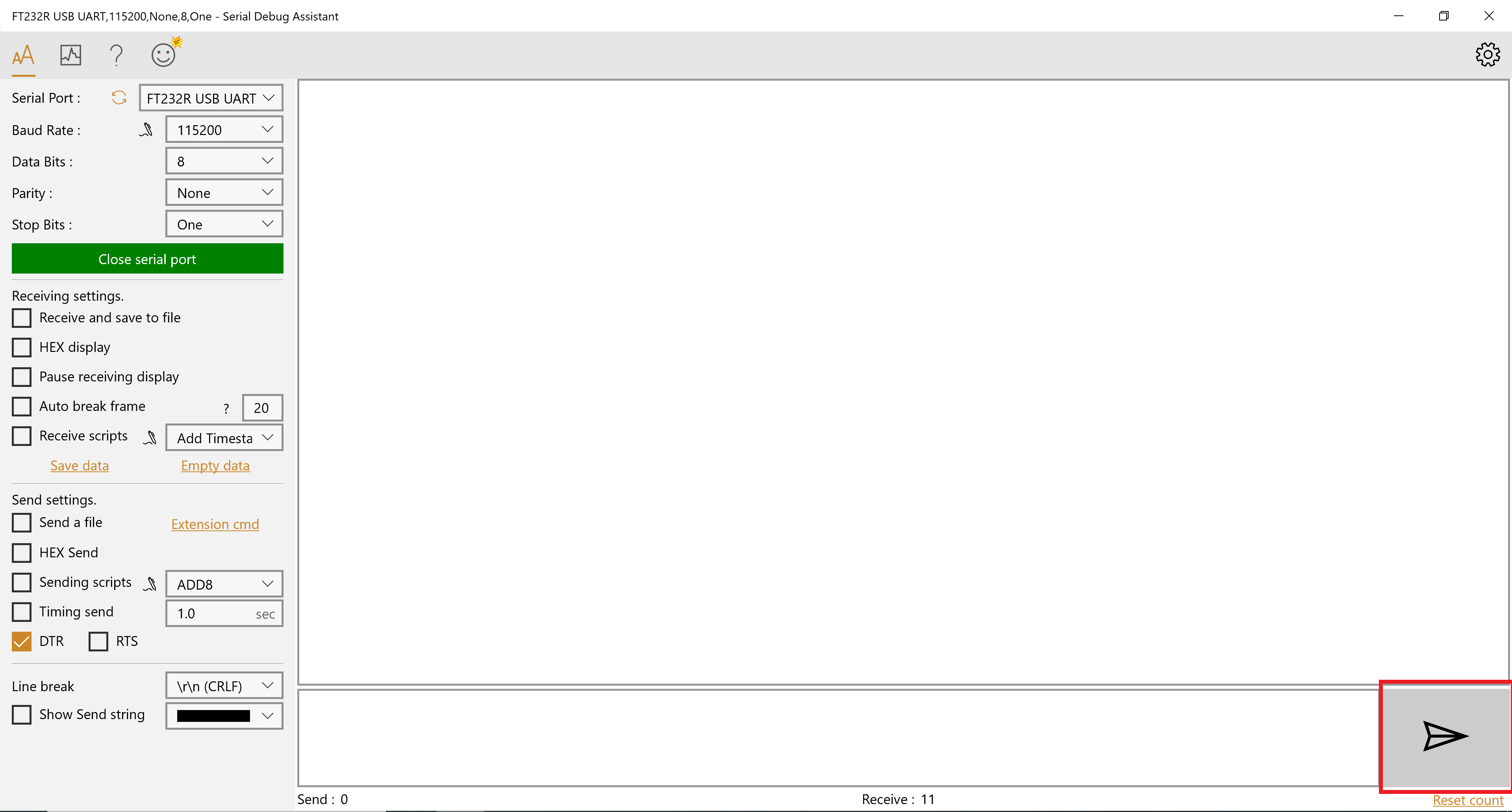
Open Serial Debug Assistant.
In the Serial Port dropdown, select the serial port to which the USB-to-TTL Converter is connected.
Click Open serial port.
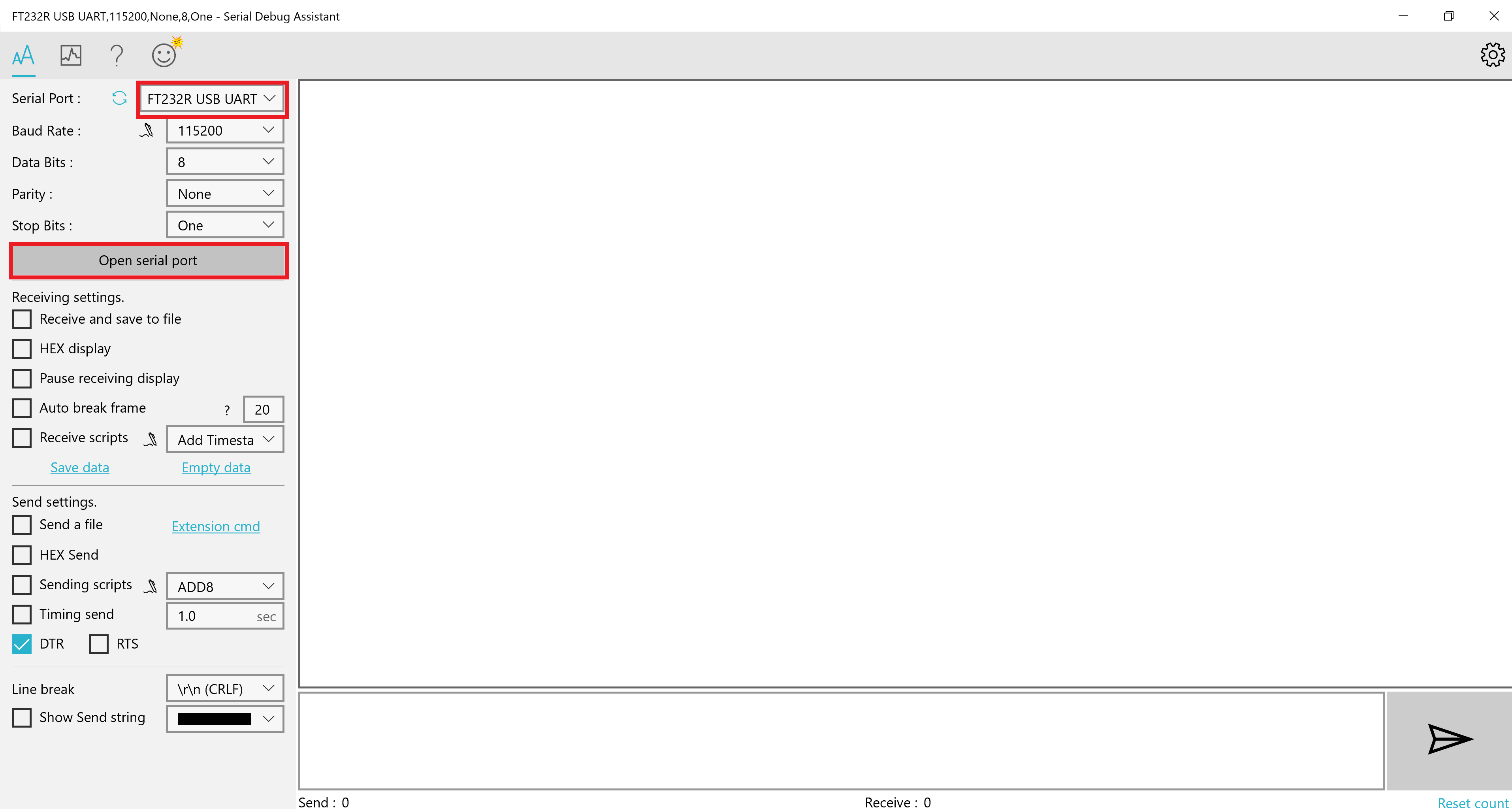
The serial port will be opened and the button will change to Close serial port.
In the input area, enter the characters you wish to send to the SiWx91x device.
Click the Send button (having an envelope icon).
Customize Application Components#
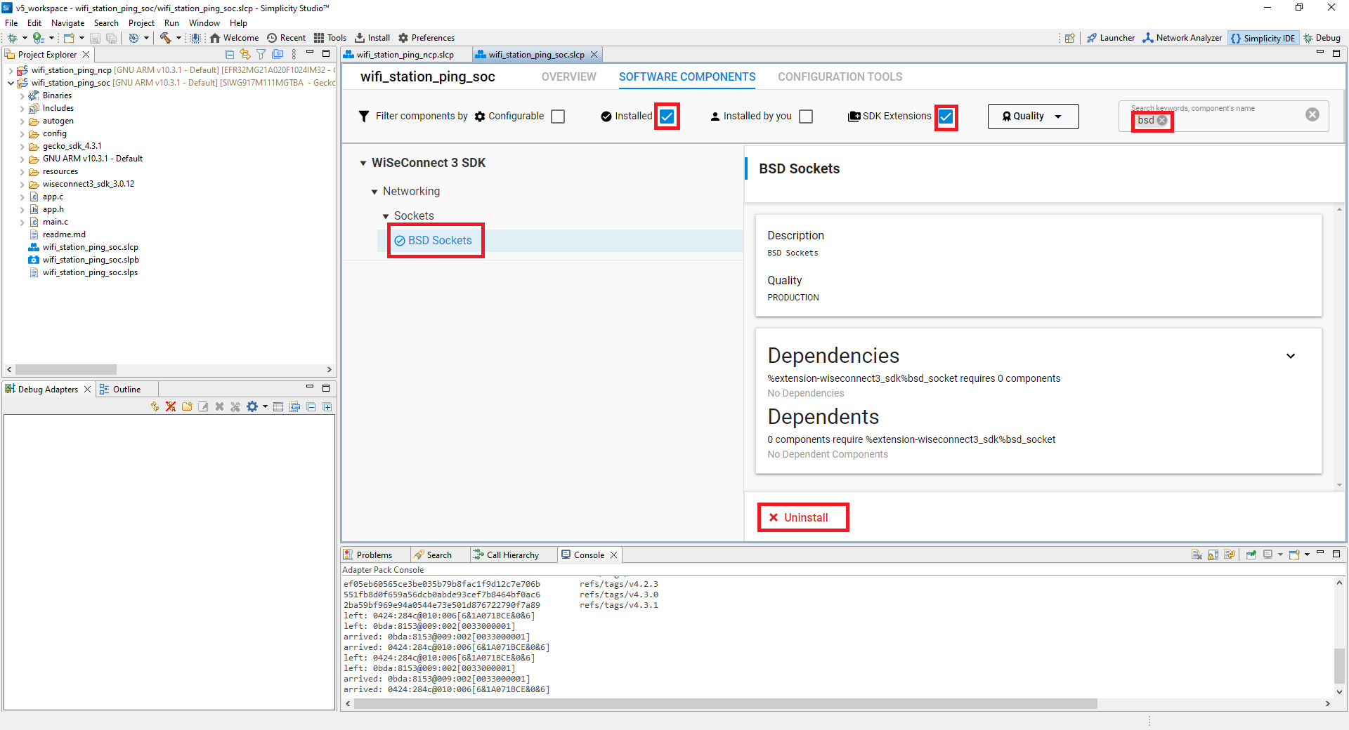
Simplicity Studio allows you to add or remove functional components in your application, such as BSD Sockets.
Add a Component#
In the Project Explorer pane, double-click the project_name.slcp file.
Select the SOFTWARE COMPONENTS tab.
Select the SDK Extensions filter.
Browse or search for and select the component that you want to install.
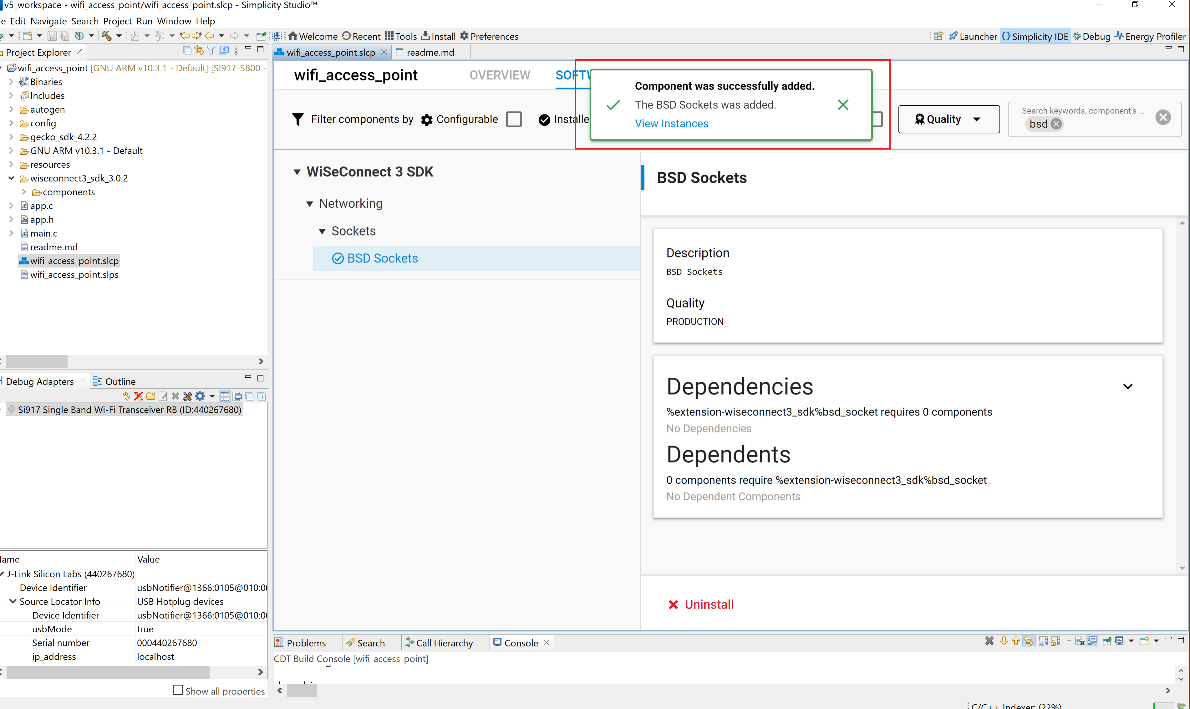
Click Install.
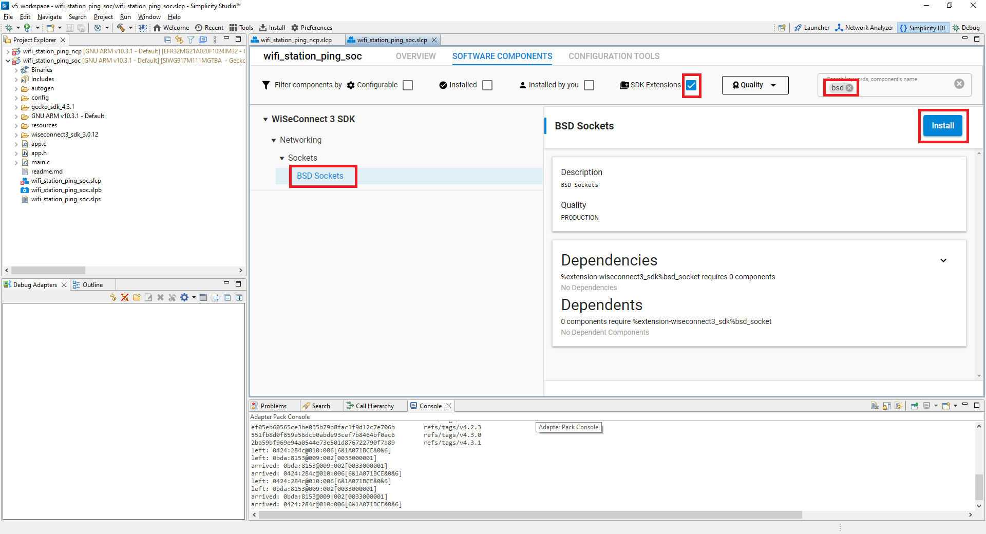
Studio will add the component and display a success message.
Remove a Component#
View the list of WiSeConnect 3 extension components by following steps 1-3 of the previous section.
Select the Installed filter to view the components you have installed.
Browse or search for and select the component you want to remove.
Select the component and click Uninstall.