


Firmware Update Images and Bootloader#
This guide describes how to generate firmware update images and configure the Gecko Bootloader for Z-Wave 800 series devices using Simplicity Studio 6 and SiSDK 2025.12.0 or later.
Note: The 700 series devices are not covered by this guide. For 700 series development and firmware update procedures, refer to the Z-Wave 7.21.x documentation.
Detailed bootloader information is available in Bootloader Fundamentals and the Silicon Labs Gecko Bootloader User's Guide for GSDK 4.0 and Higher.
Prerequisites#
Before following the procedures below, make sure the following are available:
Simplicity Studio 6 with the Z-Wave SDK and VS Code installed.
A supported Z-Wave Series 800 target board.
Simplicity Commander.
A signing key pair for signed GBL images.
An optional encryption key if encrypted GBL images are required.
A Z-Wave controller and PC Controller application for OTA testing.
Simplicity Studio installation, SDK, workspace, and Commander paths depend on the installation and user configuration. Use the paths shown by Simplicity Studio for the selected SDK and workspace instead of relying on fixed installation locations.
For the examples below, zwave_soc_switch_on_off is used as the application. Replace the project and board names as needed for the target application.
General Information#
The purpose of this section is to describe how to generate and manage firmware update images.
The SDK provides OTA and OTW bootloader configurations for supported use cases. An OTA bootloader is required for devices that receive firmware updates over the Z-Wave network. An OTW bootloader is used when firmware is transferred through a wired interface from another host controller.
For an OTA update, the transferred firmware image must be in Gecko Bootloader (GBL) format and must be signed. Encryption can additionally be used when required by the product.
A typical OTA update consists of the following steps:
Program a bootloader suitable for the target and update method.
Program the initial application image onto the device.
Configure the signing key and, if used, the encryption key.
Build a signed GBL image for the updated application.
Transfer the GBL image using the Firmware Update Meta Data Command Class.
Reboot and install the validated image.
Firmware Update Flow in Simplicity Studio 6 and VS Code#
Erase device with
Simplicity Commander.Simplicity Commander can be opened from Simplicity Studio -> Tools -> Commander, or in VS Code -> Simplicity Studio for VS Code extension -> Tools -> Simplicity Commander. Select the connected Kit, then click Flash -> Erase Chip and Erase User Data.
Or erase device by using CLI:
commander.exe device masserase -s {jlink_serial}then reset device
commander.exe device reset -s {jlink_serial}Flash the bootloader project to the chip.
Select your connected device in Simplicity Studio in the
DEVICESlist. OpenEXAMPLE PROJECTS & DEMOStab. Filter Z-Wave projects, then pressRUN DEMOonBootloader - SoC Internal Storage (OTA for Z-Wave Applications).CREATEanExample ProjectlikeZ-Wave - SoC Switch On/Offin Simplicity Studio.Open the solution's
<solution_name>.slpbfile. The SL Postbuild Profile opens in the Post Build Editor, where the signing key and optional encryption key can be configured.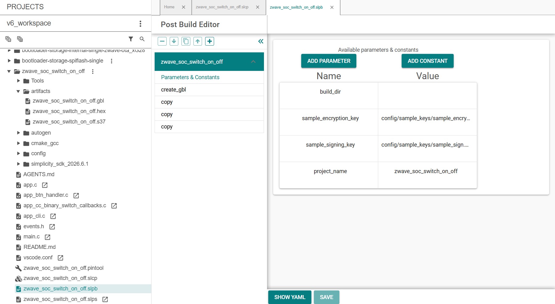
Build the project in VS Code and generate the
.hexfile.The post-build flow generates the firmware artifacts in the solution's
artifactsdirectory. For aSolution Example, the generated output can include both.gblfiles and an image containing the bootloader and Z-Wave application.Flash initial device firmware
zwave_soc_switch_on_off.hex, by clickingFlashon the project in VS Code.Flash the encryption keys.
commander.exe flash --tokengroup znet --tokenfile sample_encrypt.key --tokenfile sample_sign.key-tokens.txt -s {jlink_serial}Reset device
commander.exe device reset -s {jlink_serial}An OTA image must have a firmware version greater than the firmware version currently running on the device. For testing, a version of
255.0.0can be used to ensure that the test image satisfies the version check.Create an increased version of the Sample Application by overwriting:
#define USE_USER_APP_VERSION 0 #define USER_APP_VERSION 1 #define USER_APP_REVISION 0 #define USER_APP_PATCH 0to
#define USE_USER_APP_VERSION 1 #define USER_APP_VERSION 255 #define USER_APP_REVISION 0 #define USER_APP_PATCH 0in
config/zw_version_config.h.Then build the application again and thus create automatically the
.gblOTA image file.Note: Automatic .gbl generation also works for an
Example Project. In that case, the bootloader is not automatically merged with the Z-Wave application as it is for aSolution Example.Connect a controller or a device running a controller firmware to the PC and start the
Z-Wave PC Controllerapplication.Include the node into the network and make sure the device is visible.
In the
Z-Wave PC Controllerapplication: initiate the OTA update using the.gblimage - created in step: 9 - whose firmware version is greater than the version currently running on the target.
Generate GBL Files Manually#
The Simplicity Studio 6 post-build flow is recommended for normal development. Simplicity Commander can also be used directly when a manual image-generation flow is needed.
Generate a Signing Key Pair#
Generate an ECC P-256 signing key pair with Simplicity Commander:
commander.exe gbl keygen --type ecc-p256 -o vendor_sign.keyThis generates the private signing key, its public key, and token data that can be programmed during manufacturing. The private key must be protected and retained for the lifetime of the product if it is used to sign production firmware.
A vendor can choose a key strategy appropriate for the product portfolio, for example one key pair per product family or per product.
Generate an Encryption Key#
Encryption is optional. When encrypted GBL images are required, generate an AES-CCM key:
commander.exe gbl keygen --type aes-ccm -o vendor_encrypt.keyCreate the GBL Image#
Create a signed and encrypted GBL image using LZMA compression:
commander.exe gbl create appname.gbl --app appname.hex --sign vendor_sign.key --encrypt vendor_encrypt.key --compress lzmaIf encryption is not required, omit the encryption option and key from the command.
Generate a new GBL image each time a new firmware version is produced.
Bootloader configuration#
The bootloader resides at the start address 0x08000000 of the main flash and a fixed space of 24 KB is reserved for this. Z-Wave applications will start from address 0x08006000.
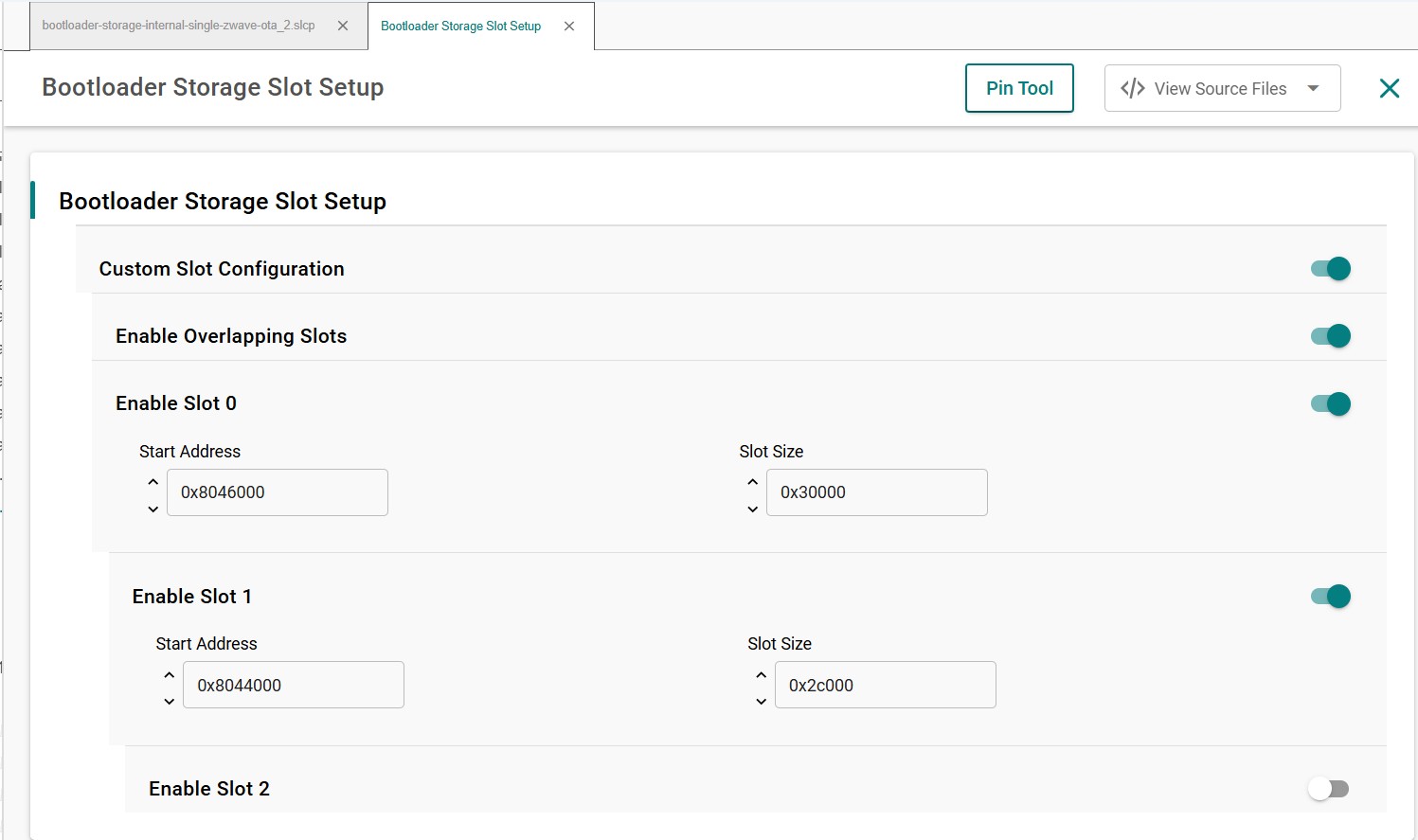
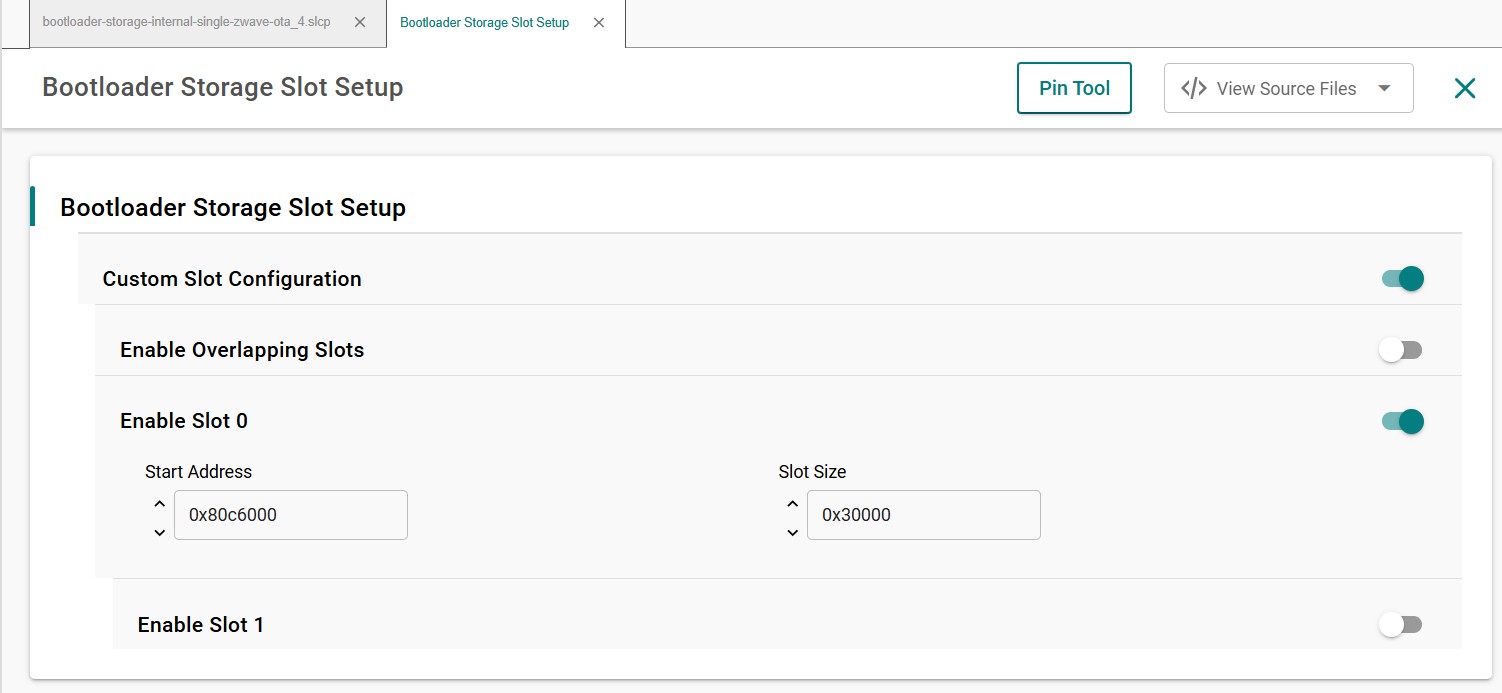
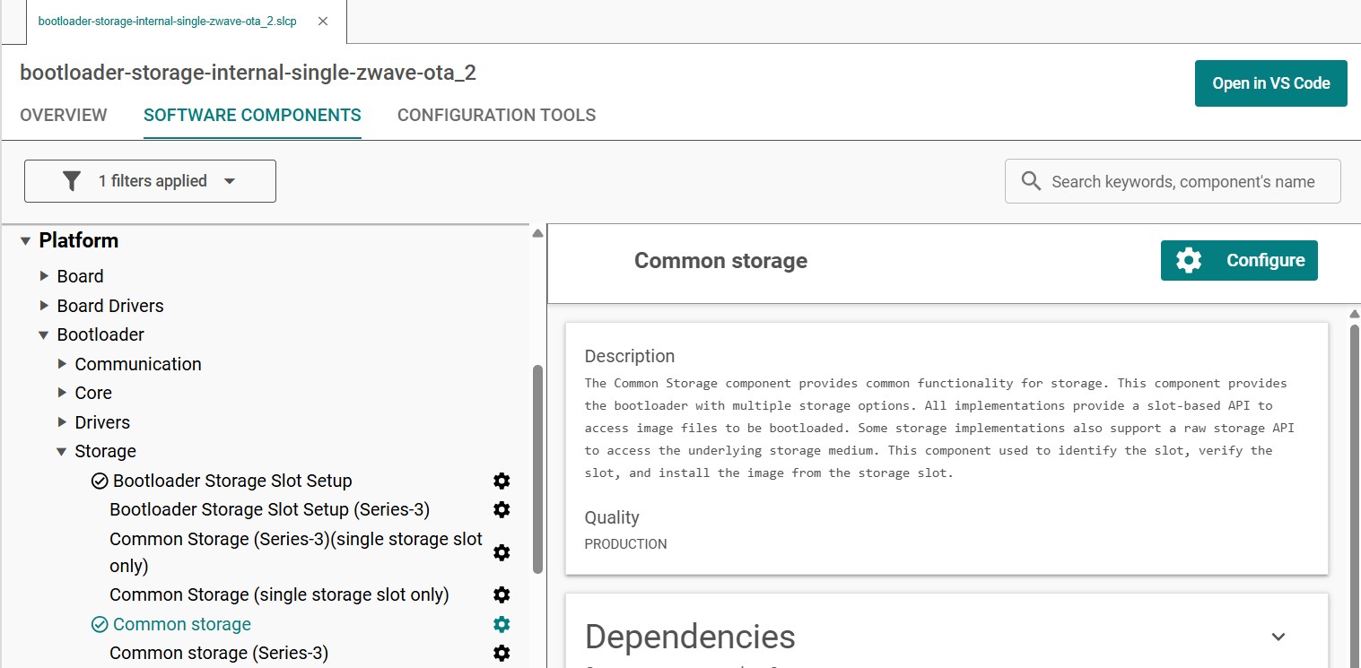
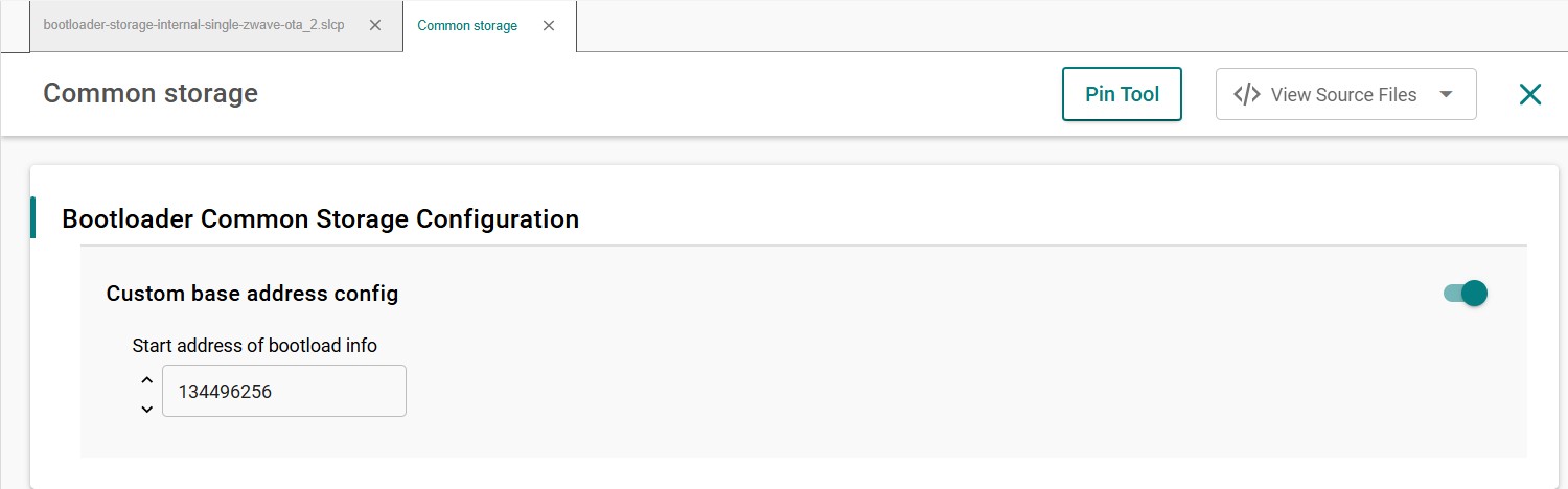
The bootloader must be flashed first before the Z-Wave sample application is flashed. It is also possible to combine the bootloader and the Z-Wave application into a single image. Use a prebuilt bootloader supplied by Simplicity Studio, or create a bootloader project and build it for the target board. When building the bootloader, the OTA image storage information must be configured as shown in the following screenshots. Importantly, this storage slot's (slot0), start address and size must not be changed.
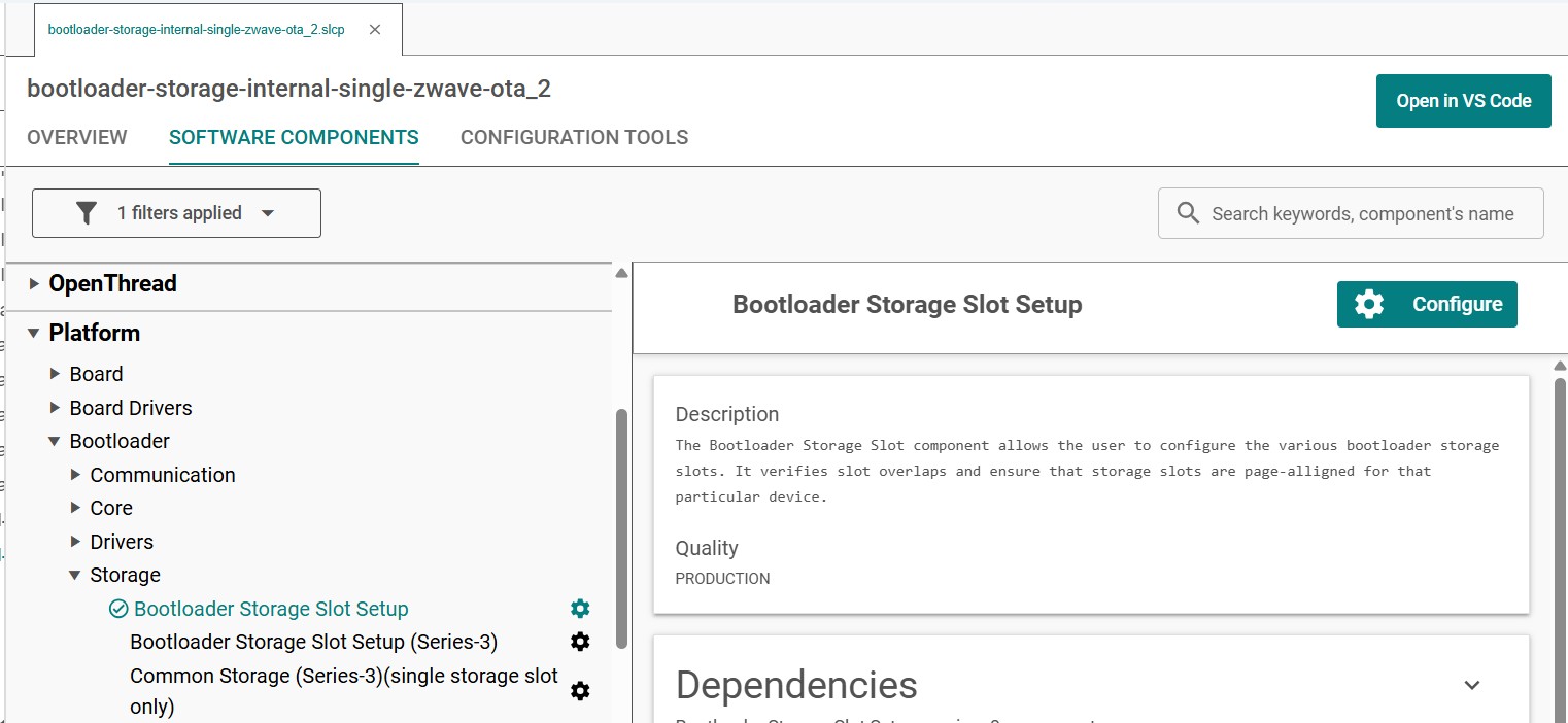
For ZG23 SoC devices:
For ZG28 SoC devices:
The Start address of bootload info for both ZG23 and ZG28 SoC types must be:
To combine the bootloader and the Z-Wave application into a single image in Simplicity Studio 6, use the solution-level post-build profile (.slpb). The related tool can be found in the project's CONFIGURATION TOOLS -> Post Build Editor. The post-build configuration generates the required GBL files for OTA updates and, for Solution Examples, can combine the bootloader and application into the generated deployment image.
Linker script#
The linker configuration supplied with the Z-Wave sample applications is already adjusted for the bootloader and OTA storage layout.
Do not modify the linker configuration unless the product has a validated custom memory layout. Changes to the application start address, bootloader reservation, or OTA storage region can make generated firmware images incompatible with the bootloader.
Bootloader compression#
Use LZMA compression for Z-Wave OTA firmware images.
The corresponding Simplicity Studio component is:
bootloader_compression_lzmaor GBL Compression (LZMA) in the GUI.
Application upgrade version#
Use the following Simplicity Studio component when application version checking is required during bootloader upgrades:
bootloader_app_upgrade_versionor Application upgrade version check in the GUI.
Custom Bootloader and External Storage#
The standard Z-Wave bootloader configuration uses internal flash for OTA image storage. Products that require a different storage architecture, such as external flash, need a bootloader configuration that matches the selected storage device and the application's firmware update implementation.
Note: Do not use the legacy 700 series linker-script procedure for 800 series devices. In particular, 700 series-specific linker files such as
zgm13-zw700.ldand the associated FLASH-size modifications do not apply to this SDK generation.
For a custom bootloader:
Create or adapt a Gecko Bootloader project for the 800 series target in Simplicity Studio 6. Good candidates for a starting project with external storage are:
Bootloader - SoC SPI Flash Storage (single image),Bootloader - SoC SPI Flash Storage using SFDP (single image),Bootloader - SoC SPI Flash Storage (single image with slot size of 1024kB),Bootloader - SoC SPI Flash Storage (multiple images).Configure the required internal or external storage component.
Verify that the bootloader storage (
Bootloader→Storage→Bootloader Storage Slot Setup) and Core (Bootloader→Core) configuration matches the firmware update configurations used by the Z-Wave application.Install software component:
Bootloader→Core→GBL Compression (LZMA).Set the followings options on in
Bootloader→Core→Bootloader Coreconfig:Require signed firmware upgrade files,Prevent bootloader write/erase,Upgrade SE without using the staging area.
Keep the application and bootloader memory layout consistent.
Build and validate the complete update flow on the target hardware before using the configuration in production.
For detailed bootloader configuration options, refer to Bootloader Fundamentals and the Gecko Bootloader User's Guide.
Erase and Read MFG Frequency#
There is a dedicated space in the flash memory where the Manufacturing Tokens datas can be stored. This area can be written once during firmware running. To save the new region the flash must be erased before.
Read token frequency: commander tokendump --tokengroup znet --token MFG_ZWAVE_COUNTRY_FREQ
Write token frequency: commander flash --tokengroup znet --token MFG_ZWAVE_COUNTRY_FREQ:0xFF
0xFF mean, this area is erased.