How to Adjust the System Crystal#
As described in Section About Crystal Tolerances, implementing the 39MHz system crystal on a PCB and connect it to the Z-Wave SoC will affect the crystal frequency. This is due to the parasitic load capacitance added to the crystal terminals by the traces from the Z-Wave device to the crystal component and due to the variance in the internal load capacitance of the Z-Wave SoCs.
To counteract the added parasitic load capacitance, the Z-Wave protocol offers the possibility to change the value of the internal load capacitance in such a way that the sum of the internal load capacitance and the parasitic load capacitance is equal to the nominal load capacitance of the crystal. When the crystal operates with the nominal load capacitance, the frequency of the crystal will also be the nominal frequency:
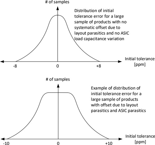
The figure above shows how the distribution of the initial frequency errors will be for two various products: one ideal product (not realistic to realize) with no parasitic capacitances at all and one product with a parasitic capacitance from both the PCB and the Z-Wave SoC.
The frequency error of an RF-enabled product can be measured by measuring the RF frequency of a Carrier Wave (CW) transmitted by the product. If the product is designed for the EU region, and a CW is enabled for, as an example, channel 2, then any measured average frequency offset from 868420000 Hz is an RF frequency error that must be corrected.
Refer to [1] to see how a CW is set up in connection with the usage of the test software RAILtest.
Since the parasitic capacitances seen by the crystal consists of two parts: A “stationary part” origin from the PCB traces and a “variable part” origin from the variation of the internal load capacitances of the Z-Wave SoC, each individual product of the product range must be calibrated during the production flow.
The frequency of a product is changed by adjusting a value called the CTune value. The determination of the CTune value for each part is an iterative process and can be described as shown below.
1 | Program RAILTest to the item to calibrate. Refer to [1] for more information. |
|---|---|
2 | For each item, follow the procedure described in [1] and measure and adjust the CW frequency. |
3 | Using the method described in [1], adjust the CTune value for this item until fmeasured = ftarget. |
4 | Program the found CTune value for the item into the flash memory of the Z-Wave SoC [2] and [3] |
The found CTune value is incorporated into the Z-Wave protocol by setting the token TOKEN_MFG_CTUNE equal to the CTune value found. For handling of manufacturing tokens, refer to [2].
Once adjusted, the average frequency error should be within ±1 ppm for each product item at 25°C.
The CTune found is valid for the specific product item. If the firmware is updated, the new firmware must use the initially found CTune value. In other words, the CTune value must follow the product item during its entire life.