Debug Challenge Interface (DCI)#
Interaction with the SE is performed over a command interface that is available through a dedicated Debug Challenge Interface (DCI). The DCI is intended to be used for various SE commands. The DCI is open while the SE is running.
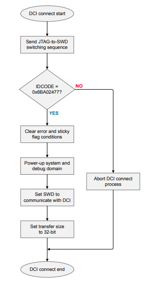
DCI Connection#
The DCI is made available through a connection on the Serial Wire Debug (SWD) port. The steps involved in connecting the DCI through the SWD port are as follows.
Send the JTAG-to-SWD switching sequence.
Read the IDCODE register (SWD DP register 0) to retrieve an identification value. On the Series 2 devices with a Cortex-M33 core, this value is
0x6BA02477.Use the ABORT register (SWD DP register 0 =
0x0000001E) to clear the error and sticky flag conditions.Use the STAT register (SWD DP register 1 =
0x50000000) to generate a system and debug domain power-up request.Use the SELECT register (SWD DP register 2 =
0x01000000) to set the SWD interface in the chip to communicate with the DCI.Use the CSW register (SWD AP register 0 =
0x22000002) to set the transfer size to 32-bit.
See AN0062: Programming Internal Flash over the Serial Wire Debug Interface for more information about the SWD port registers.
DCI Registers#
The following table lists three registers to interact with the DCI through the SWD interface.
DCI Register
Register | Description | Fields | Address | Remarks |
|---|---|---|---|---|
DCI_WDATA | Write data to the DCI | WDATA [31:0] | 0x1000 | Command |
DCI_RDATA | Read data from the DCI | RDATA [31:0] | 0x1004 | Response |
DCI_STATUS | Status of DCI accesses | Bit 0 = WPENDING | 0x1008 | Write Request to the DCI is pending. Additional writes to DCI_WDATA are discarded when this bit is asserted. |
" | " | Bit 8 = RDATAVALID | " | Response from the DCI is valid when this bit is asserted. Cleared on a read of DCI_RDATA. |
DCI Calls#
Command#
All DCI calls start by writing a 32-bit word containing the length of the DCI data followed by the 32-bit Command ID into the DCI. The length includes the length word itself, so the minimum value is 8 (4 bytes of length and 4 byes of Command ID). Then a variable length command payload (if applicable) is transferred into the DCI.
DCI Command
Command Word | Description |
|---|---|
Word 0 | Length of packet in bytes (including word 0) |
Word 1 | Command ID |
Words 2 – N | Command payload if applicable |
Response#
On completion, a 32-bit word consisting of the response length [15:0] in bytes and response code [31:16] is read from the DCI followed by the response payload, if present.
DCI Response
Response Word | Description |
|---|---|
Word 0 | Total response length (including word 0) and response code: [15:0] – Total length in bytes; [31:16] – Response code |
Words 1 – N | Response payload if applicable |
All executed commands return a response code that classifies the result of the operation. The basic meaning of these response codes is given in the following table.
DCI Response Codes
Response Code | Status | Description |
|---|---|---|
0 | SE_RESPONSE_OK | Command executed successfully or signature was successfully validated. |
1 | SE_RESPONSE_INVALID_COMMAND | Command was not recognized as a valid command, or is not allowed in the current context. |
2 | SE_RESPONSE_AUTHORIZATION_ERROR | User did not provide the required credentials to be allowed to execute the command. |
3 | SE_RESPONSE_INVALID_SIGNATURE | Signature validation command failed to verify the given signature as being correct. |
4 | SE_RESPONSE_BUS_ERROR | A command started in non-secure mode is trying to access secure memory. |
5 | SE_RESPONSE_INTERNAL_ERROR | Internal SE error. |
6 | SE_RESPONSE_CRYPTO_ERROR | Error in crypto operation. |
7 | SE_RESPONSE_INVALID_PARAMETER | One of the passed parameters is deemed invalid (for example, out of bounds), or the number of parameters is incorrect. |
8 | SE_RESPONSE_INTEGRITY_ERROR | Operation cannot be completed due to the SE having an invalid internal state. |
9 | SE_RESPONSE_SECUREBOOT_ERROR | The host application failed secure boot check. |
10 | SE_RESPONSE_SELFTEST_ERROR | Failure during self-test. |
11 | SE_RESPONSE_NOT_INITIALIZED | Feature or item is not present or not initialized. |
DCI Operation#
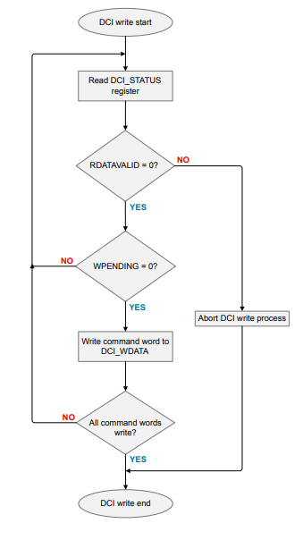
DCI Write#
The user can write the DCI_WDATA register to pass command to the SE. The steps involved in writing a command to DCI are as follows.
Connect to DCI according to DCI Connection Flowchart.
For each word in the command, follow these steps in sequence:
Set the DCI to read from DCI_STATUS by setting SWD AP register 1 to 0x1008.
Read DCI_STATUS by reading from SWD AP register 3.
If WPENDING is high, go back to step (a). If WPENDING is low, continue. If RDATAVALID is high, then the SE has started issuing a reply and the current command needs to be aborted.
Set the DCI to write to DCI_WDATA by setting SWD AP register 1 to 0x1000.
Write the command word to SWD AP register 3.
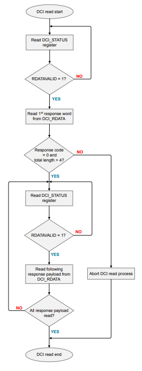
DCI Read#
The user can read the DCI_RDATA register to retrieve responses from the SE to a previously written command. If a user has sent a command according to DCI Write Flowchart on page 8, the steps to read the response from the DCI are as follows.
Set the DCI to read from DCI_STATUS by setting SWD AP register 1 to 0x1008.
Read DCI_STATUS by reading from SWD AP register 3.
If RDATAVALID is high, a response word is available to be read from DCI_RDATA. If RDATAVALID is low, go back to step (2) because the SE has not begun to reply.
Set the DCI to read from DCI_RDATA by setting SWD AP register 1 to 0x1004.
Read the first response word from the command to SWD AP register 3.
Total length of the response (including the first word) is in the lower 16 bits of that word. If this is larger than 4, for each response word:
a. Set the DCI to read from DCI_STATUS by setting SWD AP register 1 to 0x1008.
b. Read DCI_STATUS by reading from SWD AP register 3.
c. If RDATAVALID is high, a response word is available to be read from DCI_RDATA. If RDATAVALID is low, go back to step (a) because the process is polling faster than the SE can send data.
d. Set the DCI to read from DCI_RDATA by setting SWD AP register 1 to 0x1004.
e. Read the sequential response word to SWD AP register 3.