SPI Protocol Timing#
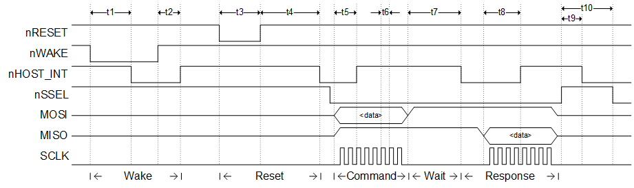
The following figure illustrates all critical timing parameters in the SPI Protocol. These timing parameters are a result of the NCP’s internal operation and both constrain Host behavior and characterize NCP operation. The parameters shown are discussed elsewhere in this document. Note that this figure is not drawn to scale, but is instead drawn only to illustrate where the parameters are measured.
Inter-Command Spacing#
The inter-command spacing is a simple time requirement needed to guarantee that the NCP has finished processing a transaction and is ready to accept a new transaction. To ensure that the NCP is always able to deal with incoming commands, a minimum inter-command spacing is defined at 1 ms between the rising edge of Slave Select (ending transaction) and the falling edge of Slave Select (starting transaction). After every transaction, the Host must hold the Slave Select high for a minimum of 1 ms. The Host must respect the inter-command spacing requirement, or the NCP will not have time to operate on the command; additional commands could result in error conditions or undesired behavior. If the nHOST_INT signal is not already asserted, the Host is allowed to use the Wake handshake instead of the inter-command spacing to determine if the NCP is ready to accept a command.
If the host is capable of blocking for 1 ms, the simplest solution is to simply burn CPU cycles for 1 ms after deasserting Slave Select. Since burning CPU cycles for 1 ms is often undesirable, Silicon Labs recommends using a simple timer. By setting or starting a timer when Slave Select is deasserted, the host can perform other tasks during the inter-command spacing. If a timer is used, the host must guarantee that any and all attempts at starting a new transaction are either blocked or stalled until the timer has expired. Once the timer has expired, the host may assert Slave Select and begin a new transaction.
SPI Protocol Timing Measurements#
Be aware that timing quoted in this document is for general guidance and should not be used for precise calculations. Timing will vary depending on factors like different hardware, different code paths, different radio traffic, and a variety of sequences that cannot be predicted.
Parameter | Description | Min. | Typ. | Max. | Unit |
|---|---|---|---|---|---|
t1(a) | Wake handshake, while NCP is awake | - | Sleepy SPI NCPs not yet supported. | - | - |
t1(b) | Wake handshake, while NCP is asleep | - | Sleepy SPI NCPs not yet supported. | - | - |
t2 | Wake handshake, finish | - | Sleepy SPI NCPs not yet supported. | - | - |
t3 | Reset pulse width | - | Refer to device's datasheet. | - | - |
t4(a) | Startup time, entering application | - | 1.1 | - | ms |
t4(b) | Startup time, entering bootloader | - | 330 | - | µs |
t5 | nHOST_INT deasserting after command | 1.0 | 1.5 | 4.3 | ms |
t6 | Clock period | - | Refer to SPI slave max timing in device's datasheet. | - | - |
t7 | Wait section | - | - | 350 | ms |
t8 | nHOST_INT deasserting after response | 1.0 | N/A | 4.3 | - |
t9 | nHOST_INT asserting after transaction | 223 | - | - | µs |
t10 | Inter-command spacing | 1 | - | - | ms |
The timings shown in the table were measured against an EFR32MG12 on a BRD4170A (which has an EFR32MG12P433F1024GM68 using a 38.4MHz high frequency crystal). All Series 1 devices will have similar timing. Ultimately, the timing depends on the EFR’s clock speed for how quickly it can respond to commands.
The parameter t4(a) "Startup time, entering application" is measured from startup/power on/pin reset to falling edge of nHOST_INT alerting the host that the NCP is ready.
The parameter t4(b) "Startup time, entering bootloader" is measured from startup/power on/pin reset with nWAKE assert to falling edge of nHOST_INT alerting the host that the NCP is ready.
The parameter t5 "nHOST_INT deasserting after command" is measured from the rising edge of the hosts transmit/command (MOSI) to rising edge of nHOST_INT.
The parameter t6 "Clock period" has to do with the speed of the SPI clock. Every EFR device has its own maximum speed for SPI Slave functionality. Refer to an NCP’s datasheet regarding maximum SPI Slave speed since the exact clock source might be different. For the device mentioned here, its datasheet lists (6 * tHFPERCLK) for minimum clock period as a SPI Slave.
The parameter t8 "nHOST_INT deasserting after response" is measured from the rising edge of NCP transmit/response (MISO) to rising edge of nHOST_INT. t8 is a very rare event since nHOST_INT is typically already deasserted and left deasserted after t5.
The parameter t9 "nHOST_INT asserting after transaction" is measured from the rising edge of nSSEL to the falling edge of nHOST_INT when the transaction is oversized. Oversized transactions are the cleanest to invoke and therefore measure. There is only a minimum value of how fast the NCP responds since it’s considered an asynchronous event with no upper limit.
SPI Protocol Timing Measurements on Different Series 1 Devices#
The preceding section details timing for an EFR32MG12 on a BRD4170A (which has an EFR32MG12P433F1024GM68). The following table shows some examples of timing across different Series 1 devices.
Parameter | Description | XG1 | XG12 | XG13 | XG14 |
|---|---|---|---|---|---|
t4(a) | Startup time, entering applications | 1.15 s | 1.11 s | 1.13 s | 1.11 s |
t5 | nHOST_INT deasserting after command | 1.5 ms | 1 ms | 1 ms | 1 ms |
t9 | nHOST_INT asserting after transaction | 254 µs | 223 µs | 235 µs | 235 µs |
These three parameters are the only ones that would vary in a meaningful way. The other parameters are not quoted across devices because:
t1 and t2 are for waking up and N/A until sleepy SPI NCPs are supported.
t3 is described by the device's datasheet and does not relate to SPI timing.
t6 is described by the device's datasheet and does not relate to SPI timing.
t8 is a very rare event since nHOST_INT is typically already deasserted and left deasserted after t5.
t7 and t10 are generous parameters allowing the NCP to complete its functionality and do not relate to SPI timing.
SPI Protocol Timing Measurements Between Series 1 and Series 2 Devices#
There is a lot of timing variability between all the devices, especially when it comes to configuration, app activity, stack activity, and all other behaviors that occur with a Host and NCP.
For general comparison of timing, the parameter t5 is used because it is the most common and fundamental behavior of the NCP reacting to a host command. Remember that t5 is nHOST_INT deasserting after command.
The following table shows some statistics of t5 timing, in microseconds, after the Host boots up and resets the NCP.
Device | Min. | Max. | Median | Std Deviation |
|---|---|---|---|---|
EFR32xG12 | 411 | 4674 | 1303 | 622 |
EFR32xG21 | 264 | 4008 | 1032 | 539 |
EFR32xG24 | 289 | 4002 | 955 | 529 |
This table shows that Series 2 is faster than Series 1, but there is no major variation.
Interfacing EZSP to the EZSP-SPI Protocol#
Due to the serial nature of the EZSP (that is, transactions must occur in sequence instead of overlapping), Silicon Labs recommends that the EZSP interface into the SPI Protocol through a polling driven mechanism. For example, after calling a function sendCommand(), the EZSP could continually call a function pollForResponse(). Otherwise, the EZSP implementation should be carefully coded to prevent the host from accidentally overlapping transactions.
If the host’s EZSP-SPI Protocol is implemented using interrupts, the host should be careful to never perform a transaction inside of an interrupt context. This is especially important because a transaction could require up to 350 ms or a wake handshake could require up to 300 ms.