Strategies for Testing and Debugging Mesh Networking Applications#
Introduction#
Development and testing of embedded applications has always relied on specific testing and debug strategies, such as the use of emulators or JTAG, to isolate problems. This has worked well when a problem exists on a single device, or between two devices communicating with each other. Commercial development and deployment of larger distributed embedded network applications has required another level of testing strategies. Without planning of the testing and debug process, development projects can stall in a cycle of bug fixing, field testing, bug fixing, and field testing until hopefully all problems have been resolved. Silicon Labs has participated or assisted in the development and deployment of a number of commercially available wireless products, and recommends a series of specific testing strategies throughout the development process. The development strategy and testing processes required are similar even if the products being developed are aimed at different marketplaces.
This section reviews the typical successful testing methodology, and the hardware and software tools required to qualify products. It provides a testing outline and methodology that can be used for software qualification. Consideration of this testing methodology is critical from the beginning of the development efforts to ensure suitable means for qualification are built into the software, including appropriate means for simulating testing and recording test results. Real world examples and test setups are used to illustrate the proposed testing strategies. The key areas of testing to be covered are:
Hardware and application considerations for testing and debug
Initial development and lab testing
Beta criteria and field trials
Release testing process and criteria for release
Hardware and Application Considerations for Testing and Debug#
Initial Software Application Development using Development Kit Hardware#
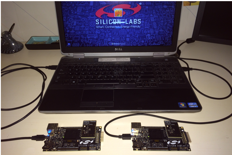
Initial development of customer applications typically starts using development kit hardware (see the following figure) that is available from the chip and software supplier. These kits universally have some level of serial or Ethernet debug capabilities, to allow viewing what is occurring at the application as well as at the software stack. It is important for a developer to start with these tools to evaluate what information is available and how it can be used in development, debug, and testing.
Some typical choices to be made early include:
Will the software provide debug information out a debug port or serial port for later use in debug and testing? Such information can be critical to evaluating problems later and can significantly shorten the debug process. However, use of a serial port may slow the application and impact normal operation. A serial port may also not be available during normal system operation. Even if not normally available, a serial or debug port can be populated on prototype hardware for early stages of testing. For example, Silicon Labs hardware includes a dedicated debug port that can be used by the application and also includes stack trace and packet trace information.
How will software be monitored and upgraded during internal testing? Software must be regularly updated during development and initial testing. For these systems it is recommended that a means of rapidly upgrading software on all devices be included even if it is not included on final field hardware. For example, on Silicon Labs Wireless Gecko development kits the dedicated debug and programming port can be accessed over an Ethernet or USB backchannel. During initial development and testing, use of this wired backchannel is recommended for both software upgrading and system monitoring.
How will software be monitored and upgraded during field testing? Initial field testing will also result in periodic updating of software. However, mechanisms used during internal testing may be impractical during actual field testing. An over-the-air (OTA) bootloader is recommended for software upgrading during field testing. A debug channel is impractical for all devices during field testing. Instead, it is recommended that selected nodes such as gateways be monitored with a debug channel and that sniffers be used to monitor the network.
What mechanisms will be provided for system testing and qualification? It is important to be able to trigger system-level events and normal operations during qualification testing. This can be done either manually by operating the system or it can be done using backchannel or serial port mechanisms, but it must be considered early in the design.
Initial application development and testing efforts on development kit hardware should consider each of these questions. Depending on the particular hardware being designed, it may or not be practical to include all of the recommendations above, but they should be considered.
Transition to Custom Hardware#
Most customers move to the hardware specifically designed for their application as soon as practical. However, the limitations and constraints of the custom hardware design may make it impractical to include monitoring and debug ports. At a minimum, tests points should be included to allow access when required.
If monitoring and debug ports are not practical on the custom hardware, it is recommended that development continue on both custom hardware and the development kit hardware so full debugging capabilities are available on at least some of the hardware. For devices based on Silicon Labs wireless SoCs, the debug port is often the programming port. This should be available on initial hardware designs since devices typically will be programmed many times during development and debug.
Many networks have a centralized base station, gateway, or controller node. This plays a critical role in the network and therefore plays a critical role in monitoring and debugging the network. If other devices cannot have a debug and monitoring port, this device should include one.
Questions about debug access and programming must be considered on the customer hardware during the design phase to avoid a hardware re-spin later to add these capabilities. Software engineers should review schematics to ensure the capabilities provided in hardware match those required for software development and debugging.
Initial Development Environment and System Testing#
Initial development and testing is typically done on a desktop or benchtop environment to ensure a basic application is operational before expanding to a larger network.
Debug Library#
During prototyping, developers usually will want to link debugging functionality in their project. This is typically provided through an optional component selected from within the Simplicity Studio IDE. For example, the Zigbee application framework provides Debug Basic Library and Debug Extended Library components for supplementing the stack with debugging capabilities. Available APIs for debugging are described in an ember-debug.h file, typically included in a stack/include subdirectory within the stack installation. A full description of these interfaces can be found in the online stack API reference.
Note: Once the application has met all design goals, the debugging functionality can be turned off in the final build by removing the related components. Debug access should be secured by the method applicable to the platform. See UG103.5: IoT Endpoint Security Fundamentals for more information on this and other security best practices.
Single Device Testing and Debug#
One of the early steps in starting a new application is to isolate the network to several devices and focus on the message flow and application logic. This may be as simple as light and a switch or a controller and a single device. This testing validates the simple messaging protocols.
For devices with very specific and time-critical operations, debugging on a single device is necessary to ensure proper operation. This is common on devices doing lighting control or dimming, where precise timing is needed to maintain lighting levels. In these cases it is important to develop and debug the application using specific debug tools connected to the individual device. Because timing may be affected by operation of the network stack, this testing must also be done during network-level testing, to verify proper operation of the individual device.
System Test Scenarios#
Once single device testing and debugging is completed, more directed system-level testing is required. This directed testing should reflect the expected network operating environment and conditions, in order to detect problems that otherwise would occur in the field.
For any system-level testing, it is important to define the expected operations under specific network and application scenarios. These include the following:
System Start Up: The expected normal system start up and commissioning should be validated and tested.
Typical System Operation: The expected normal system operation and data flow through the network should be tested to ensure smooth and consistent operation.
Security: Many applications run extensive lab and field testing before turning on security. The use of security can make troubleshooting and debug more difficult, depending on the sniffer tools used. It is important to have a debug system that decrypts the packets prior to display. Use of security impacts the payload size available for the application, and increases system level latency due to more node processing time. The impact of security on system level performance needs to be identified early in the system-level testing.
Stressed System Operation: If the system has particular devices that generate messages based on user interaction, these items should be tested well beyond normal operation to understand the behavior when the system is more stressed. The acceptable behavior under these conditions must be defined and then tested. For example, in some systems it may be acceptable to discard a message under high traffic conditions and send another message later. In other systems the application should retry sending the message.
Power Failure and Restart: Systems may lose power either partially or totally due to a power outage or building maintenance. The system has to react and recover from power failure and resume operations. Battery-operated sleeping devices must conserve power during this loss of network connectivity and then rejoin the network once it restarts. The expected time of the restart varies based on the application design and use of sleeping devices. The behavior of the application on this restart should be defined and tested.
Performance Testing: Many applications have specific requirements for end-to-end latency, delivery reliability or other system criteria. These specific metrics should be defined and a means for clearly measuring the metrics during testing should be determined.
Typical Application Failure Cases: Failure mechanisms may vary for different systems, depending on network topology. However, typical failure cases should be identified and added to the test plan for each stage of development. Typical scenarios include:
low battery on end device
loss of end device
loss of parent (child fail over to new parent)
loss of routers in network
loss of gateway, border router, or other access point
System Level Test Networks#
In addition to the test scenarios above, dedicated test setups are necessary to establish the conditions expected in the field. In Silicon Labs' experience, ad hoc testing does not uncover all the expected use cases and therefore directed testing to force these network conditions is required.
In each of these test setups, it is not necessary to run directed or specific tests. However, the full range of typical expected operating conditions should be exercised.
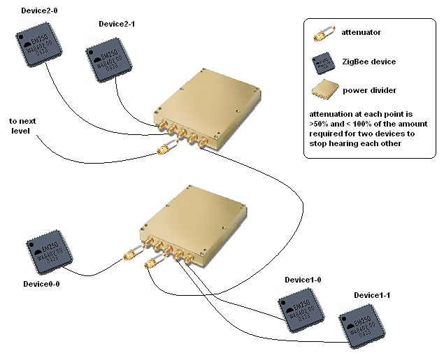
Multihop Test Network#
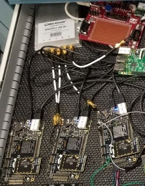
Actual field conditions are not always known, and actual radio range under the expected installed environment are not known. A multihop test environment should be established. Sometimes testing is done on an ad-hoc basis with desktop or office networks, but more than one hop is not tested. One method we have used to ensure testing a multihop network is to build a wired test network with splitters and attenuators in the RF path. This provides a repeatable test environment for regression testing. The following figure shows such a set up. It includes RF cabling, connectors, attenuators, and splitters. Each splitter can represent three nodes at a particular network depth. The signal is then attenuated to the next splitter that forms the next hop in the network. A network can be built of as many hops as are expected. This test should be built to replicate as many hops as expected in the field installations, or at least five hops.
Dense Network#
Dense networks often can present a challenge, as the network has to deal with increase in table sizes and message flow. The application also experiences more delays in message flow since all radios within range must share time on the air. It is recommended that at least 18 nodes be included in this testing.
Large Network Testing#
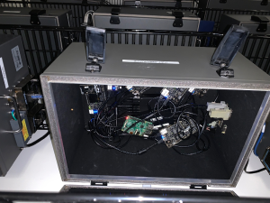
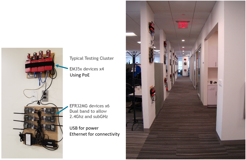
After the above dedicated tests, software can then be tested in a large-scale test network, as shown in the following figure. The test clusters are controlled through a private Ethernet backchannel to allow:
Firmware updates
Command line interface
Scripting
Timing analysis
Packet capture
A central test server manages and controls devices.
Coexistence and Interference Testing#
Testing should also consider other wireless systems that may be operating in the expected environment. Almost any type of typical installation is likely to have to share the 2.4 GHz band with Wifi or 802.11 type traffic, Bluetooth, cordless phones, baby monitors and the many other devices that share the 2.4 GHz band. Depending on the expected field conditions, consider including any of these devices during system-level testing.
Moving to Beta and Field Trials#
Hardware and Test System for Larger System Testing#
Beyond the more dedicated test systems discussed above, it is necessary to move to a wider system level test environment within development and then within initial field testing.
While a stack provider like Silicon Labs can have dedicated setups for various conditions, as well as a larger test network with complete debug connectivity, this is not always practical for the typical application developer. Instead, the developer must focus on realistic tests that can be set up and operated within the budget and space constraints of their project.
First and most importantly, it is usually not practical to have full backchannel analysis capability for a wider scale system on custom hardware. This does not mean the developer should give up on the use and analysis of debug data, just that it has to be acquired in different means. Some techniques are:
Full Sniffer-Based Environment: If the custom hardware does not have any access for debug data, dedicated sniffers can be used. To be useful they should be spread throughout the system to capture and send as much data as possible back to one central log file.
Partial Sniffer and Debug Data: If some of the custom hardware has accessible debug ports, a hybrid system of some debug ports and additional sniffers to fill out the network picture can be used. This is especially valuable if some central control devices can be monitored using debug while more remote areas of the network are monitored using sniffers.
Full Debug Environment: If problems are seen with either of the above setups, ask the stack provider to operate the application in their more dedicated test network with full debug access. While this involves porting the application to development hardware, it does provide full debug capabilities for more difficult problems.
For any of the test environments used for the full system testing, several critical items must be included for proper testing and debugging. These include:
Mechanisms to activate typical application-level operations. The full system setup should provide scripting or other means to force application-level actions, so the system can be repeatedly tested. A problem that is seen once but cannot be replicated because of an uncontrolled test environment is difficult to resolve.
Centralized logging of all sniffer and debug information. Where possible it is important to have a central computer that is collecting data into a single log file. This is critical for time-stamping events, duplicate detection and removal, and proper analysis of the events leading up to a problem.
Means for simple code upgrade in all devices in the network. The best designed system will have bugs and features that require upgrading of software in the test network. A means to upgrade all devices easily offers a faster development and testing process.
Reproducing Common Field Conditions or Problems#
Typical field problems occur due to several conditions that are not replicated in testing prior to initial field deployments. Evaluation under expected conditions while still in a controlled test setup saves many hours and later trips to the field installations.
Many of these conditions occur under error conditions in the network that were not tested in initial testing.
The most common problems Silicon Labs has experienced in field settings are as follows:
Multi-hop Performance: While it sounds unusual, many customers operate on desktop test networks that are generally one hop, and do not test multi-hop performance until an actual field installation occurs. Adding hops in the network obviously adds routing complexity that the network is intended to handle. However, it also increases packet latency and the response time an application can expect. If the application cannot handle this higher latency, then message failures or excessive retries occur in the field.
Density or Sparsity of Network: Desktop testing of units, even those units that are on the final field hardware design, often does not replicate expected field conditions. Often devices are installed in walls or ceilings, within metal enclosures, with metal panels or shields over the device, or more widely spaced than any lab testing. In addition, use of particular network features such as broadcasts or multicasts is impacted by the density or sparsity of the network.
Required Application Interrupt Timing Under Network Loading: Some applications require tight control over interrupt latency to perform critical functions. However, the networking stack also requires interrupt-level processing on receipt of messages. While the network has the ability to buffer messages, this buffering is limited based on the memory of the device. Under actual network conditions, nodes that run out of buffer space temporarily lose the ability to send and receive messages. Alternatively, servicing network-level interrupts over application level interrupts results in poor application-level performance.
Excessive Network Traffic: A common complaint is a network that appeared to be operating well has a decrease in throughput or increase in latency. Upon investigation excessive traffic in the network resulted in congestion, lost messages and degraded performance. The most common reason is ongoing broadcasts or multicasts within the network. Failed messages can then lead to more broadcasted route discoveries, leading to further decreases in performance.
Initial Field Deployments#
Initial field deployments are a critical step in the development process. These tests validate decisions and testing done throughout the development process and uncover any issues prior to wider deployment. These deployments are normally restricted to several sites, and are carefully monitored and controlled.
The following items are critical for initial field deployments:
Monitoring and Analysis Plan in Place: The initial deployments of a field system require the ability to monitor and analyze the system performance. This can be done at the system level by keeping track of application-level failures, or it can be done at a lower level by including some level of sniffers or debug capability in the field network.
Clear Operational Criteria and Success Criteria: Before installing a field system, the operating criteria and success or failure criteria should be established so these items can be monitored throughout the deployment.
Ability to Escalate Problems: Many networks have third party components or systems, or critical subsystems such as the networking stack. A clear process for escalation and resolution of bugs is critical to ensure issues are identified and closed in a timely manner.
Release Testing and Criteria for Release#
For release of a wireless product, it is important to follow a progressive testing process that starts with desktop testing, and proceeds through laboratory testing, initial field deployments, and release testing. The earlier a problem is identified, the simpler it is identify and resolve. Bugs are estimated to take 10 to 50 times longer to resolve in a field deployment than in laboratory or office testing.
The release process is an accumulation of the testing discussed above. However, it is typical to have some final test process and validation for final release. This criterion varies among different companies but often includes the following elements:
Normal System Operation: Typically, this involves running a normal system in a typical environment for some period of time with no failures.
Power Cycling and Restart: This testing is done on a repetitive basis to ensure uncontrolled power loss and restarting does not result in failed devices. Typically, Silicon Labs sees this done on a small network with automated power cycling. No failures are allowed.
The following table shows which testing strategies are employed during the different phases of development.
Monitor Mechanism | Single Device Development | Desktop Development | Lab Testing | Initial Field Testing | Release Testing |
|---|---|---|---|---|---|
Full debug access | XX | XX | |||
Partial debug | XX | XX | XX | ||
Sniffer based | XX | ||||
Dedicated Test Types | |||||
High density | XX | XX | |||
Multi-hop | XX | XX | XX | ||
Mobile node | XX | XX | XX | ||
Large Network | XX | XX | |||
Coexistence / Interference | XX | XX | |||
System Test Cases | |||||
System Start Up | XX | XX | XX | ||
Normal operation | XX | XX | XX | ||
Security | XX | XX | |||
Stressed Operation | XX | XX | |||
Power failure and restart | XX | XX | |||
Performance | XX | XX | |||
Typical failure mechanisms | XX | XX |
The following figure shows how to set up a wired network as described in this document.
The following table gives a list of required parts needed to build the wired networks described in this document.
Part | Supplier | Part Number |
|---|---|---|
Mini-Circuits 8-port power divider | Mini-Circuits | ZB8PD-4-S+ |
Mini-Circuits 4-port power divider | Mini-Circuits | ZN4PD1-50-S+ |
Mini-Circuits 2-port power divider | Mini-Circuits | ZN2PD2-50-S+ |
Mini-Circuits 10 dB attenuator | Mini-Circuits | VAT-10 |
Mini-Circuits 20 dB attenuator | Mini-Circuits | VAT-20 |
Mini-Circuits 30 dB attenuator | Mini-Circuits | VAT-30 |
Mini-Circuits terminator Male SMA | Mini-Circuits | ANNE-50L+ |
Richardson Elec 24" SMA-to-SMA patch cable | Richardson | 1-3636-461-5224 (last two digits are the length) |