


Set Up and Run your Zigbee 4.0 Project#
This page provides a tutorial for setting up and running your first Zigbee 4.0 project. If you’re an experienced user, you’ll notice several similarities to the Zigbee 3.0 boot camp found in the zigbee_hands_on_forming_and_joining document. However, a few minor differences simplify the process.
Simplicity Studio Projects#
This example uses a Z4 Light as the coordinator and a Z4 Switch as the end device joiner. You can also use the Z4 Gateway application as the coordinator. The Z4 Gateway project is a host application that connects to either the Zigbee Daemon (zigbeed) or an NCP application. You can find more information about these options in later sections of this page.
This example uses the following two projects:
Zigbee - SoC Z4 Light
Zigbee - SoC Z4 Switch
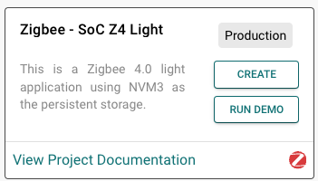
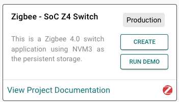
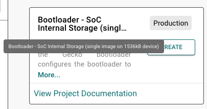
If the Bootloader project isn't already available in Simplicity Studio, you'll need to create it:
By default, the Z4 Light can behave as a coordinator that forms a Z4 network or as a router that joins an existing network. The Z4 Switch is configured as an always-on end device.
These two projects contain all the required software components to demonstrate a compliant Zigbee 4.0 network. If you aren't using these projects, install the following software components in the projects you're using:
Coordinator:
Stack > R23 support (SoC/NCP/Zigbeed)
Stack > Dynamic Commissioning (SoC/NCP/Zigbeed)
Zigbee 4.0 > BDB 3.1 Trust Center Extension (SoC/Host)
Zigbee Security Manager Dynamic Link Key support (SoC/NCP/Zigbeed)
Router/End-device (SoC/NCP/Zigbeed):
Stack > R23 support
Stack > Dynamic Commissioning
Zigbee 4.0 > BDB 3.1 Rejoin Algorithm
Zigbee Security Manager Dynamic Link Key support
Erase both boards, and then flash the Bootloader on the corresponding Light and Switch boards. Before you continue, make sure that you can access the CLI on both boards.
Open Commander from the Simplicity Studio Tools tab. For each device, select the Flash tab, and then select Erase chip to erase the board contents.
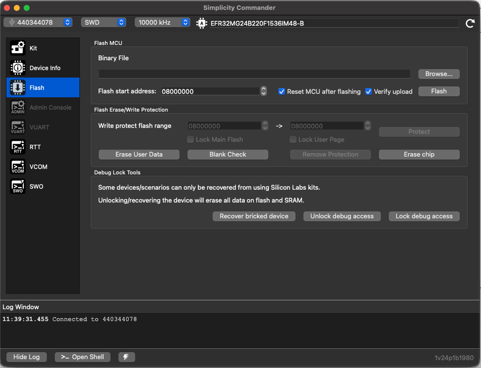
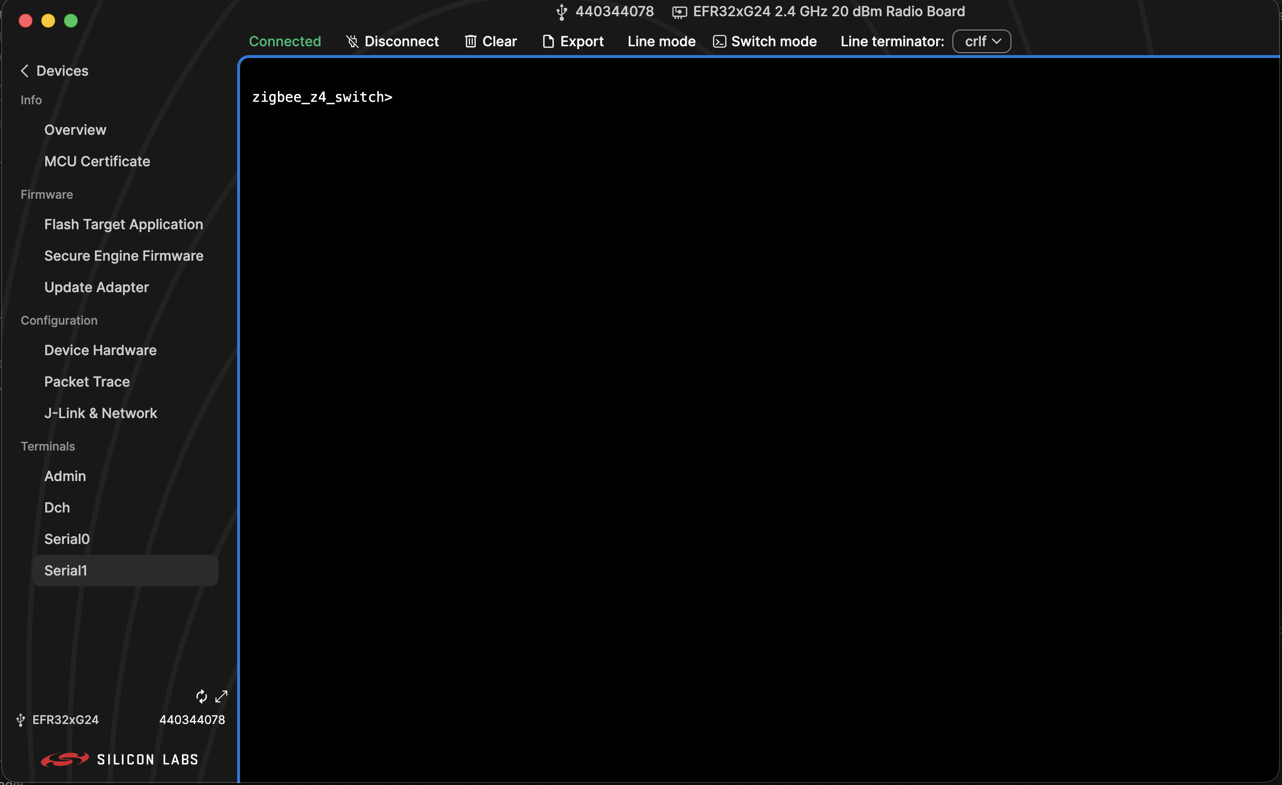
Both boards are now completely blank. Open the Light, Switch, and Bootloader projects in Visual Studio. Build and flash the Bootloader onto each board. Then, build and flash the Light and Switch projects. Finally, to verify that the projects are running successfully, open the Simplicity Device Manager from the Simplicity Studio Tools tab. For each device, open the Serial1 terminal and confirm that it's usable. The project name appears before the cursor unless you specified a different name in the Simplicity Studio project, as shown in the following screenshot.
Flashing the Install Code#
This section explains how to check the install code on an EFR32 device, manipulate keys, and use the Windows and Mac install scripts.
Checking the Install Code on an EFR32 Device#
Before you begin, verify that your computer can connect to the device and check the information currently stored on the node.
Connect only the Switch device to your computer. If multiple devices are connected, a pop-up dialog will prompt you to select a device.
Run the following command to print the manufacturing token data from the EFR32-based device.
$ C:\Users\%USERNAME%\.silabs\slt\installs\archive\Simplicity Commander\commander.exe tokendump --tokengroup znet
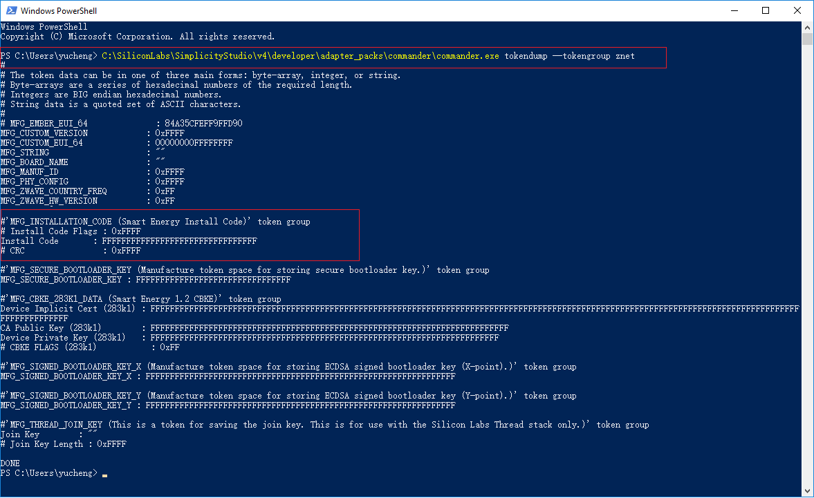
The tokendump command prints the manufacturing token data as key-value pairs. Simplicity Commander supports multiple token groups. This example uses the znet token group.
If you haven't previously written an install code to the device, the output should look similar to the following screenshot. The highlighted area shows the fields related to the install code.
Note: If the
commandercommand isn't available in PowerShell, verify that Simplicity Commander is installed correctly. Also verify thatcommander.exeis in this directory:C:\Users\%USERNAME%\.silabs\slt\installs\archive\Simplicity Commander. The screenshot uses the Simplicity Studio 4 path.
Key Manipulation#
Unlike Zigbee 3.0, Zigbee 4.0 doesn't permit a device to join a network using the global default Trust Center link key. Instead, each joining device must use unique credentials. For the procedure in this guide, provision the device with an install code before it joins the network.
Zigbee 4.0 devices use the Dynamic Link Key (DLK) feature to securely establish an APS key using the install code. The lack of an install code will result in a join failure.
Although this process describes creating and joining a network by using an install key as the security mechanism for Zigbee 3.0, the equivalent Zigbee 4.0 process uses DLK to secure the network.
Note: To comply with the additional Zigbee 4.0 security requirements, don't use the
open networkcommand to open the network.
You can program the install code into the Switch device in several ways. Each method uses Simplicity Commander to write the install code to the manufacturing area of the Switch device.
For this hands-on exercise, use the following batch file to program the install code automatically:
Windows install script:#
Click to expand and view the Windows install script
@echo off
:: THIS FILE IS USED FOR PROGRAMMING INSTALLATION CODE AUTOMATICALLY.
:: use PATH_SCMD env var to override default path for Simplicity Commander
if "%PATH_SCMD%"=="" (
set "COMMANDER=C:\Users\%USERNAME%\.silabs\slt\installs\archive\Simplicity Commander\commander.exe"
) else (
set "COMMANDER=%PATH_SCMD%\commander.exe"
)
:: default file extension of GCC and IAR
set DEFAULT_INSTALL_CODE="83FED3407A939723A5C639B26916D505"
:: change the working dir to the dir of the batch file, which should be in the project root
cd %~dp0
if not exist "%COMMANDER%" (
echo Error: Simplicity Commander not found at '%COMMANDER%'
echo Use PATH_SCMD env var to override default path for Simplicity Commander.
pause
goto:eof
)
echo **********************************************************************
echo Program the default installation code to the specified device
echo 1. Erase the Installation Code if existing
echo 2. Program the Installation Code into the Manufacturing Area of the specified Device
echo 3. Check the Stored Installation Code
echo **********************************************************************
echo.
%COMMANDER% flash --tokengroup znet --token "Install Code: !ERASE!"
echo.
%COMMANDER% flash --tokengroup znet --token "Install Code:%DEFAULT_INSTALL_CODE%"
echo.
%COMMANDER% tokendump --tokengroup znet --token TOKEN_MFG_INSTALLATION_CODE
pauseMac install script:#
Click to expand and view the Mac install script
#!/bin/bash
# USAGE
# You can run this file in the command line from this directory
# You may need to run the command: chmod +x program_install_code.sh
# to give the shell script the proper permissions to run.
# Then run the command: ./program_install_code.sh {serial number}
# If there is only one board connected then leave {serial number} empty
COMMANDER="/Applications/Simplicity Studio.app/Contents/Eclipse/developer/adapter_packs/commander/commander.app/Contents/MacOS/commander"
DEFAULT_INSTALL_CODE="83FED3407A939723A5C639B26916D505"
SERIAL_NUMBER=$1
# Change directory to the Simplicity Commander path
cd "/Applications/Simplicity Studio.app/Contents/Eclipse/developer/adapter_packs/commander/commander.app/Contents/MacOS"
echo
echo "**********************************************************************"
# Check the value of the MFG Token
echo "CHECKING THE VALUE OF THE MFG TOKEN:"
if [ -z "$SERIAL_NUMBER" ]; then
"$COMMANDER" tokendump --tokengroup znet --token TOKEN_MFG_INSTALLATION_CODE
else
"$COMMANDER" tokendump --tokengroup znet --token TOKEN_MFG_INSTALLATION_CODE --serialno "$SERIAL_NUMBER"
fi
echo "**********************************************************************"
echo
echo "**********************************************************************"
# Overwrite the MFG Token
echo "OVERWRITING THE MFG TOKEN:"
if [ -z "$SERIAL_NUMBER" ]; then
"$COMMANDER" flash --tokengroup znet --token "Install Code: $DEFAULT_INSTALL_CODE"
else
"$COMMANDER" flash --tokengroup znet --token "Install Code: $DEFAULT_INSTALL_CODE" --serialno "$SERIAL_NUMBER"
fi
echo "**********************************************************************"
echo
echo "**********************************************************************"
# Check the value of the MFG Token again
echo "CHECKING THE UPDATED MFG TOKEN:"
if [ -z "$SERIAL_NUMBER" ]; then
"$COMMANDER" tokendump --tokengroup znet --token TOKEN_MFG_INSTALLATION_CODE
else
"$COMMANDER" tokendump --tokengroup znet --token TOKEN_MFG_INSTALLATION_CODE --serialno "$SERIAL_NUMBER"
fi
echo "**********************************************************************"Format of the Install Code File#
As an alternative to the script, the user can install the code by invoking Simplicity Commander directly with the install code value, without the CRC. The command format is commander flash --token "Install Code: "<ascii-hex>"
For example:
commander flash --token "Install Code: 83FED3407A939723A5C639B26916D505"
Verifying the Stored Install Code on an EFR32 Device#
After writing the install code, it's best to verify the information by running the following command again:
$ C:\SiliconLabs\SimplicityStudio\v5\developer\adapter_packs\commander\commander.exe tokendump --tokengroup znet

Creating and Joining the Network#
After the install code is flashed onto the joining device, run the following commands on the coordinator to create and open the network. The joining device can then join the network.
Coordinator (Light):
plugin network-creator start 1
option install-code <link key table index> {<Joining Node's EUI64>} {<16-byte install code + 2-byte CRC>}For example:
option install-code 0 {00 BE 44 FF FE C0 48 C3} {83 FE D3 40 7A 93 97 23 A5 C6 39 B2 69 16 D5 05 C3 B5}The first argument of the option install-code command is the link key table index, which is 0 in this example. The second argument is the EUI64 of the joining node, which is the Z4 Switch in this example.
You can find this information by running the info command on the joining device's CLI.
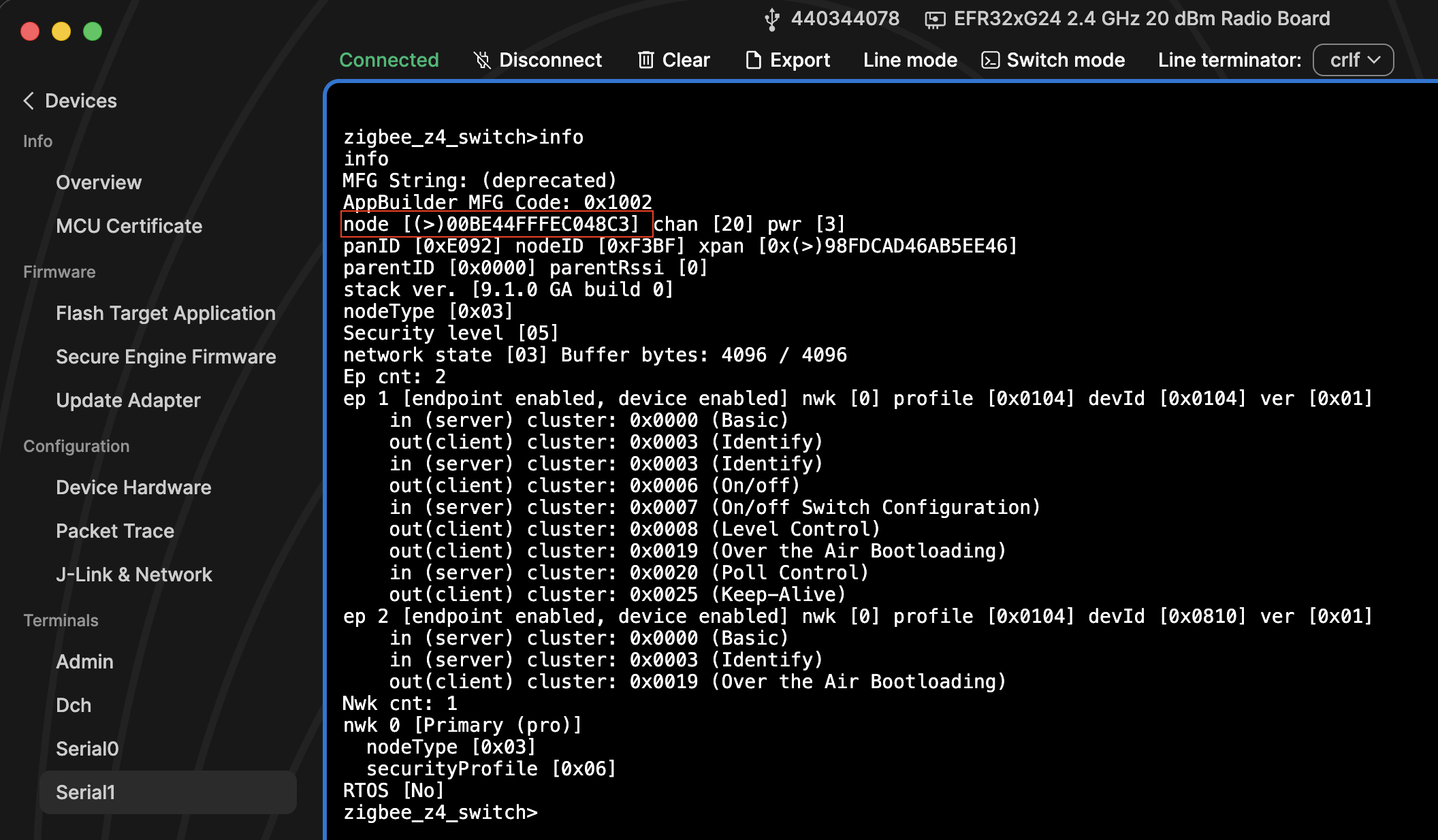
The third argument is the install code flashed onto the joining device with its two-byte CRC. The tokendump command output provides the CRC in little-endian format. Reverse the CRC bytes before including them in the option install-code command.
The command returns the link key. For the install code used in this example, the link key is always {66 B6 90 09 81 E1 EE 3C A4 20 6B 6B 86 1C 02 BB}.
Use the joining node's EUI64 and the link key to open the network.
Coordinator (Light):
plugin network-creator-security open-with-key {00 BE 44 FF FE C0 48 C3} {66 B6 90 09 81 E1 EE 3C A4 20 6B 6B 86 1C 02 BB}The network is now open. Run the following command on the joining device to join the network:
Joining device (Switch):
plugin network-steering start 1Inspecting the Exchange#
This section explains how to use Network Analyzer and Wireshark to inspect and decode the DLK exchange.
Network Analyzer#
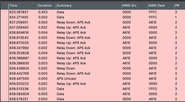
At the time of writing, Network Analyzer shows Relay Up and Relay Down messages but doesn't dissect the packets any further. For more detailed packet decoding, use Wireshark to inspect the DLK exchange. To do this, export the Network Analyzer capture into a Wireshark-compatible file type using the following steps:
Select File > Export... > Network Analyzer Export...
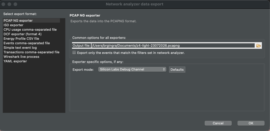
Select the PCAP NG exporter format.
Append the
.pcapngextension to the file name.Select OK to generate the Wireshark-compatible file.
Wireshark#
After you open the exported file in Wireshark, add the network keys so that Wireshark can decode the capture.
Open the Wireshark Preferences menu. On a Mac, use ⌘ + comma. On Windows, use Ctrl + Shift + P.
Select Protocols, and then select Zigbee from the list of protocols.
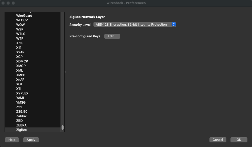
The Security Level should already be set to "AES-128 Encryption, 32-bit Integrity Protection." If it isn't, select this value.
Add the keys using the following steps:
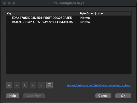
Select Edit to open the Pre-configured Keys menu.
Add the required keys.
Leave Byte Order set to Normal and remove any spaces from the keys.
Select OK.
The following example shows two keys in the menu. Only the link key is required because Wireshark picks up the network key during the initial join procedure if the network trace includes it.
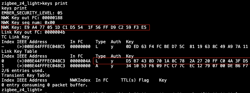
To identify the link key, enter "keys print" in the coordinator device's CLI. Copy the Network Key and the Link Key from the Link Key table where the type is equal to L. If you encounter decryption issues, add the network key manually.
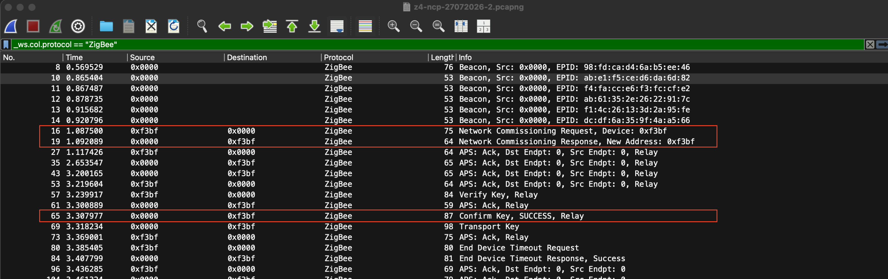
The trace should now decode correctly. The following packets indicate a successful Dynamic Link Key exchange:
196 -1844 0xa303 0x0000 ZigBee 76 Network Commissioning Request, Device: 0xa303
249 -1842 0x0000 0xa303 ZigBee 86 Confirm Key, SUCCESS, Relay
Using a Co-Processor#
This section explains how you can use a Network Co-Processor (NCP) or Radio Co-Processor (RCP) to set up a Zigbee 4.0 network.
Network Co-Processor (NCP)#
If you use an NCP in a Zigbee 4.0 project, modern SDKs will install and configure the required software components by default. For an example network setup, see Network Co-Processors Theory of Operation
However, verify the following components in the NCP project to make sure it can use Dynamic Link Keys:
Zigbee > Utility > Zigbee Device Config: Select Configure, and set Primary Network Security Type to "Zigbee 4.0 Security".
Zigbee > Stack > Dynamic Commissioning: Make sure that this component is installed.
You don't need to make any changes to the Zigbee 4.0 Gateway project.
Radio Co-Processor (RCP)#
Setting up a Zigbee network with an RCP is more involved than setting up an NCP network, whether you use Zigbee 4.0 or not.
Before you begin, familiarize yourself with System Architecture and the subsequent pages about setting up a Zigbee network with an RCP. As part of this process, create a Zigbeed project in Simplicity Studio and copy it to the host file system, similar to the Gateway application. You can skip sections about protocols other than Zigbee, such as Bluetooth or OpenThread.
In this setup, make two changes to the software components in Simplicity Studio with SDK version 2026.6.0:
Zigbeed: Install Zigbee > "Zigbee ARM64 (arm64v8)". This required component depends on the host architecture.
Zigbee Z4 Gateway: Install Zigbee > Utility > "EZSP UART".
Note: This tutorial assumes that you use UART and not SPI.
If you have any issues compiling these projects on the host, check for missing or unnecessary software components.
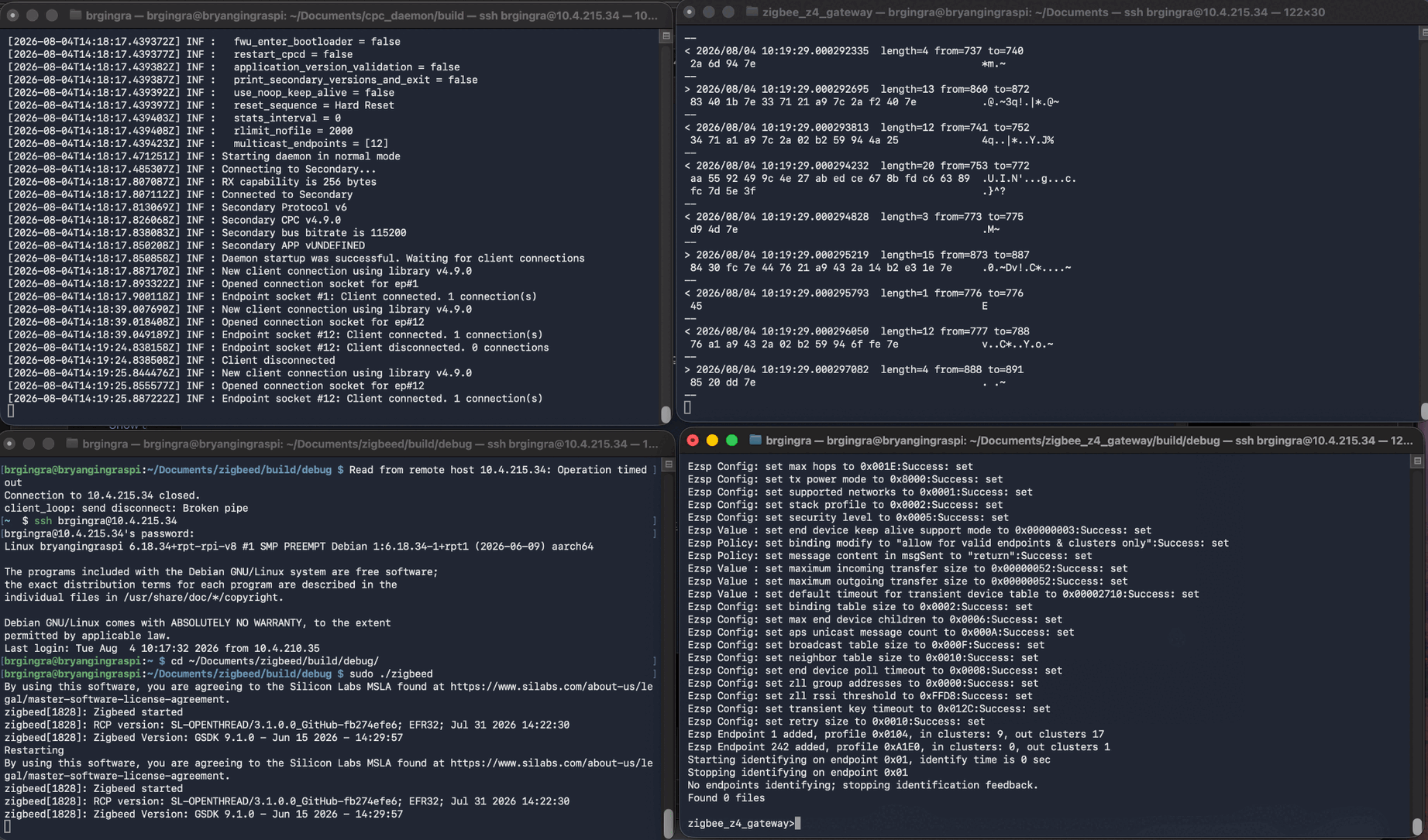
After you build or install the CPC daemon (CPCD), Socat, Zigbeed, and the Zigbee 4.0 Gateway on the host, run them in this order:
CPCD
Socat
Zigbeed
Zigbee Z4 Gateway
You can run the applications as services or directly from their binaries. For faster results, open four separate terminal windows connected to the host device and run one application in each window.
For information about running the applications concurrently, see Building the Zigbee Host Locally.
The following screenshot shows the four applications running concurrently in the specified order.
Use the following command to launch the Z4 Gateway:
sudo ./zigbee_z4_gateway -n 0 -p /dev/ttyZigbeeNCPthe -n 0 argument sets the NCP defaults. The -p /dev/ttyZigbeeNCP argument specifies the Socat link that connects Zigbeed and the host application.
If the Gateway binary doesn't accept these arguments, check the software component configuration. The Gateway project might be missing the EZSP UART component described earlier.
Troubleshooting#
Use the following troubleshooting information to resolve common issues when joining or rejoining a network.
Joining or Rejoining#
Before each attempt to join or rejoin the network, clear the keys from the joining device.
keys clear
network leaveThis prevents keys from previous attempts from being used during the join process.
The keys clear command deletes all keys from the key table, including keys for other joining devices. To delete a key for a specific joining device, use keys delete {index}.
Secure Engine Firmware#
If you still have trouble joining the network, check the version of the Secure Engine firmware.
For example, MG21 boards require Secure Engine firmware version 1.2.13 or later. In Simplicity Commander, go to the Device Info tab. In the Secure Engine Status section, check Firmware Version.
If you need to update the firmware, follow these steps:
Download the latest release from gecko_sdk/util/se_release/public.
Download the appropriate
.hexfile.Flash the
.hexfile to the board using Simplicity Commander.Reflash the bootloader to the board.