Using the Pin Tool#
This section discusses the basic operation and functions of the Pin Tool. Before proceeding to the next section, it may be helpful to understand the GPIO functionality and peripheral signal routing controls of the target devices by reviewing AN0012: General Purpose Input Output, device datasheets, and reference manuals.
Opening the Pin Tool in Simplicity Studio#
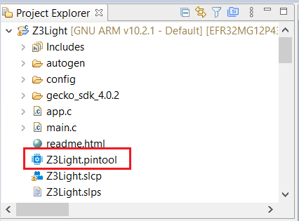
Open Pin Tool directly by double-clicking on the <project>.pintool file in the Project Explorer, as shown in the following figure.
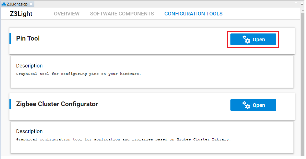
Pin Tool may also be started from the Project Configurator’s CONFIGURATION TOOLS tab.
Pin Tool Functions#
The following figure shows the Pin Tool editor window once it is open. The left “Port I/O” pane shows the device package’s Port I/O view. The right “Configure” has three tabs –Pin, Functions, and Peripherals. Each of these tabs gives a different detailed perspective with which to configure the hardware.
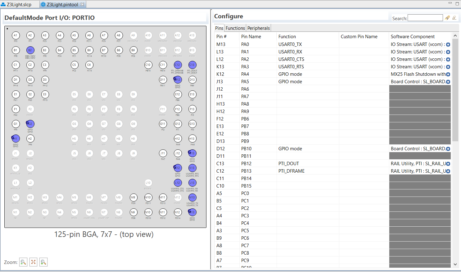
Port I/O Pane#
The Port I/O Pane is essentially a Pinout diagram that displays the physical pin locations on the target device package.
The Pinout diagram has the following color coding:
Pins in blue are in use
Pins in white are unused.
Pins in red show unallowed conflicts with two or signals going into the same pin.
Pins in orange show allowed conflicts with two or more signals going into the same pin (not shown in the diagram).
Pins, such as E5/Vss, are greyed out because they are unavailable for configuration
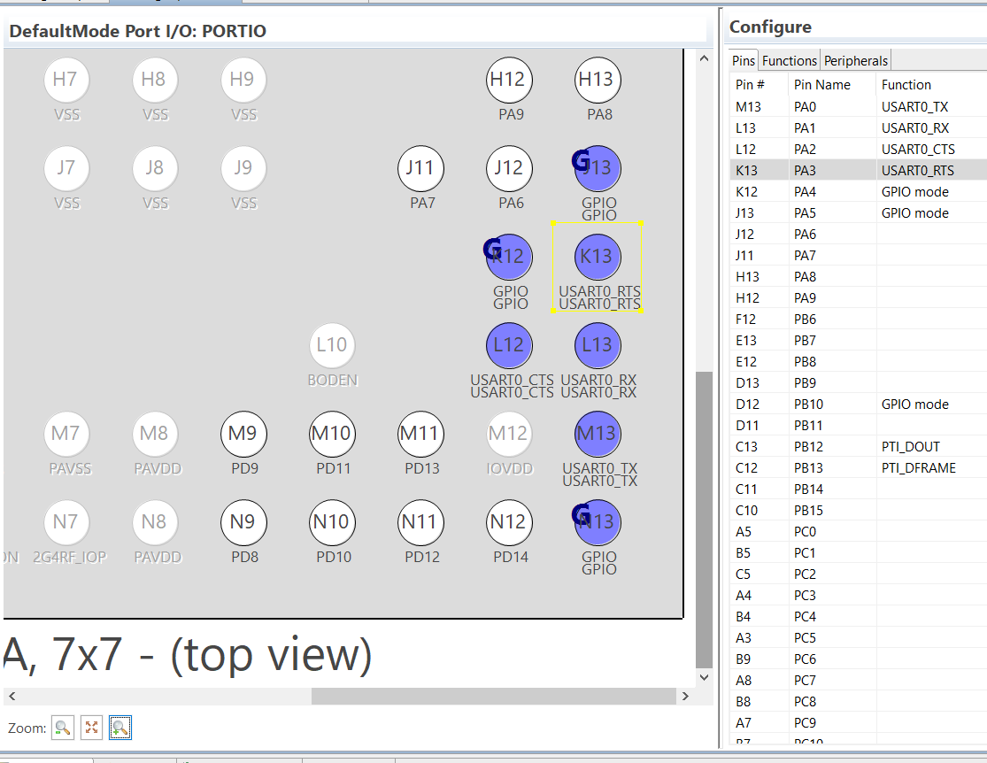
All pins configured for GPIO modes are marked by the boldfaced letter G.
When one or more pins are selected in the Configure panel (e.g., K13), the corresponding pins are highlighted in yellow.
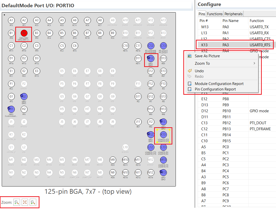
The Zoom controls at the lower left corner of the Port I/O pane provide a convenient way to zoom in to a specific location on the Pinout diagram to see more detailed information of a given pin.
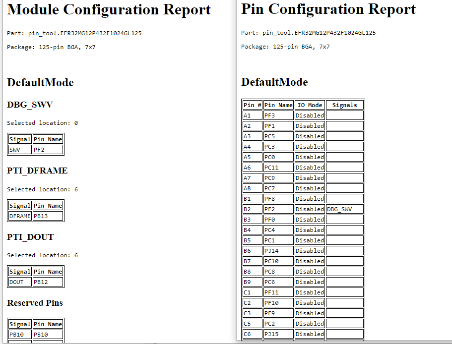
A printable report can be generated by right-clicking the pinout diagram and selecting Pin Configuration Report. This opens a report as a webpage in a browser that can be saved, printed, or archived. The Module Configuration Report option generates a similar set of tables organized by module rather than by pin order.
Pins Tab#
The Pins tab gives a pin-centric table view of the device, similar to the datasheet’s GPIO Functionality Table. The Pins table lets the user assign any valid alternate function to a pin, as shown in the following drop-down menu under the Function column.
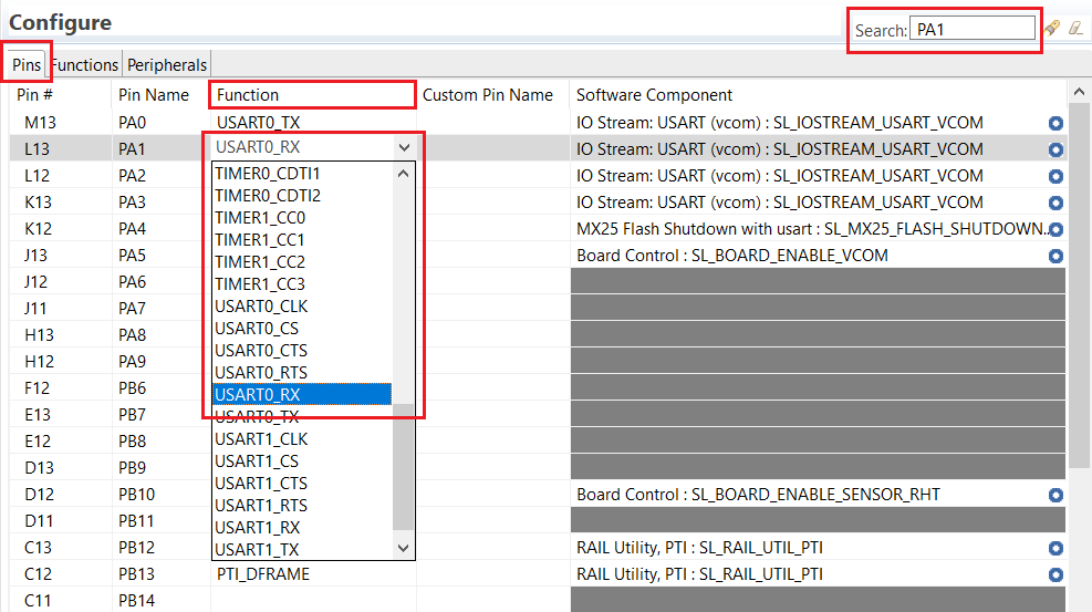
The Search box shown in the above figure allows user to quickly locate a Pin in a table.
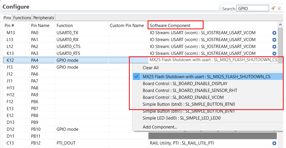
Once a pin and the function have been chosen, the software component can be selected from the Software Component drop-down menu for the pin. The following figure shows the pin PA4 has been configured for GPIO mode and assigned to the software component MX25 Flash Shutdown with usart. Alternatively, the user can assign the pin through the Component Editor.
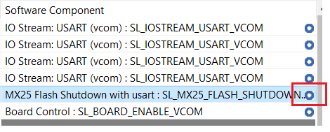
As a convenience, the user can open the Component Editor for a given component by double-clicking the blue circle in the “Software Component” cell as shown below.
The “Custom Pin Name” column allows users to enter the custom pin name for a given pin.
Functions Tab#
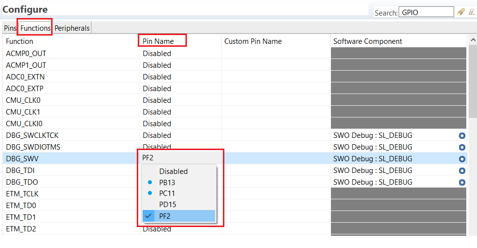
The Functions tab provides an alternate function-centric view of the device, similar to the datasheet’s Alternate Functionality Table. The Functions tab lets the user assign available pins to an alternate function.
The valid pin for a specific alternate function can be selected from the drop-down menu in the “Pin Name” column. The blue dot for a pin in the same drop-down menu indicates the pin is already in use. The Component Editor can be opened for the entries in the “Software Component” column.
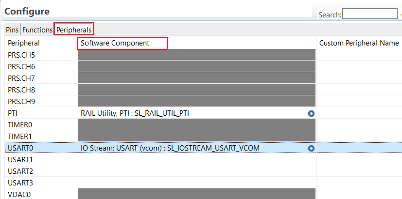
Peripherals Tab#
The Peripherals tab shows a list of the peripherals on the device and their mapping to software components. The drop-down menu allows the user to select an available software component for a specific peripheral, as shown in the following figure.
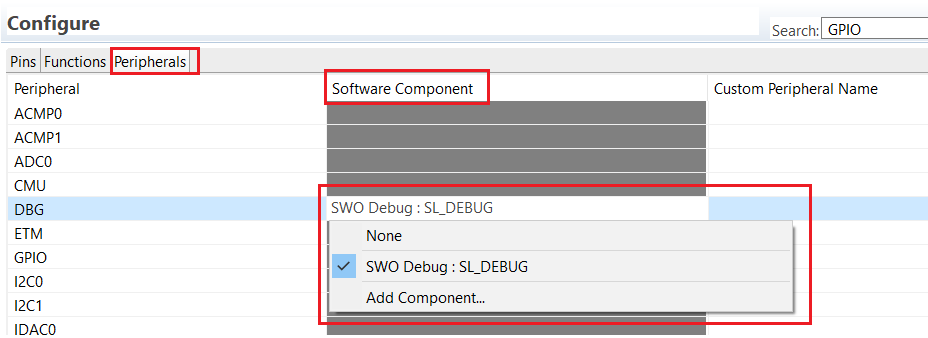
The Software Component cell for a peripheral appears grey when no software component that uses the peripheral exists, and white when one exists but has not been assigned. The user can also provide a custom name for a given peripheral in the “Custom Peripheral Name” column.