Zigbee Design Choices#
Although the application framework simplifies and abstracts the design process, some design decisions must be made as part of implementation. The following design choices are applicable when developing applications for Zigbee protocols, including Zigbee PRO:
Single Network or Multi-Network
Network Discovery / Commissioning Method
Device Discovery and Provisioning Method
Route Establishment Method
Message Delivery Method
NCP and Host Application Compatibility
Single Network vs. Multi-Network#
A single network node is a node that forms or joins one network and must leave that network before forming or joining a second network. EmberZNet PRO 4.7 introduced the possibility for a node to be concurrently part of more than one network.
Note: For EmberZNet PRO, multi-network support is limited to two networks. More than two networks may be supported in the future.
Until now, any device required two physical chips to be part of two networks. For instance, a device that is designed to be a gateway between an HA (Home Automation) PAN (personal area network) and an SE (Smart Energy) PAN would join the first network using the first chip and the second network using the second chip. The application had to manage two pieces of hardware, resulting in increased complexity for the hardware and the application designer.
A multi-network stack removes the 1-to-1 mapping between logical PANs and physical chip, extending it to an n-to-1 mapping. An application for a device with a single chip can be designed to be part of multiple PANs possibly running different security profiles (for instance HA and SE). Use of one instead of two chips results in cost savings from reduced hardware requirements and reduced complexity of the hardware and application code design.
Some applications still require a dual-chip configuration. This configuration is needed if the device needs to be coordinator or router on two networks (see more details below) or if the application needs to operate on two different stacks such as EmberZNet PRO and Silicon Labs Connect.
Multi-networking on a single chip is achieved by timesharing the chip’s only radio on the networks. In other words, the multi-network node resets all the radio parameters between the networks according to a network scheduling algorithm.
The fact that the node is concurrently active on more than one network is totally transparent to the application. APIs allow the application to specify which network a set of API calls are referred to. Similarly, APIs allow the application to understand which network a stack callback is related to. See Designing for Multiple Networks on a Single Chip, for more details regarding dual network APIs.
Both the Zigbee Application Framework and the Network Coprocessor Application Framework provide dual network support. The application framework provides many advantages in terms of reduced complexity, mostly related to how the framework seamlessly manages the different network contexts.
Typically a multi-network stack switches network, or retunes the radio on a different network, when an outgoing packet needs to be sent on a particular network. During the non-transmission time, the radio is always tuned on one of the networks, according to the stack’s internal network scheduling algorithm.
There are some restrictions to the roles a node can assume on the networks. Since a coordinator or a router node is expected to keep the radio constantly on listening for incoming packets, a multi-network node can be coordinator or router on only one network, while it must be a sleepy end device on the other networks.
Note: A node can assume any role on one network, but must be a sleepy end device on the other networks.
The networks in which a node participates can be on different channels, different PAN IDs, different short IDs, different profiles, and so on. However, a multi-network node maintains the same EUI64 address across the networks in which it participates. The next sections discuss in more detail the two basic configurations, the first where the multi-network node is a coordinator or router on one and a sleepy end device on all other networks, and the second where it is a sleepy end device on all networks.
Coordinator / Router Network + Sleepy End Device Network(s)#
A multi-network node that is a coordinator/router on one network and a sleepy end device on the other networks should spend most of its time on the coordinator/router network. A network scheduling algorithm seamlessly takes care of switching from one network to the other so that the node is always on the coordinator/router network except for short periods of time. In particular, the node temporarily leaves the coordinator/router network to complete certain transactions on the sleepy end device networks, such as polling/data retrieving from the parent and/or data sending to the parent. These transactions are typically initiated at the application layer. Therefore the application designer should design the application so that the node does not spend too much time away from the coordinator/router network. Having a multi-network node too busy on a sleepy end device network can consistently impact the throughput of the node and in general could delay all the traffic that gets routed through the node on the coordinator/router network.
In Designing for Multiple Networks on a Single Chip, Silicon Labs provides data obtained from extensive experiments that show the average duration of some typical polling and data transactions between a sleepy end device and its parent. The document also includes a detailed study on how the activity on the sleepy end device network impacts the throughput on the coordinator/router network. With this data, you can make educated design choices based on how much traffic the multi-network node will handle on the sleepy network and how this traffic impacts the performance of the coordinator/router network.
Notice that even if the node behaves as a sleepy end device on most of the networks, if it is also a coordinator/router on any one network, it will not be able to save energy by temporarily shutting down the radio (sleep mode).
Multiple Sleepy End Device Networks#
A multi-network node that is a sleepy end device on all networks does not need to keep its radio always on. The node can poll with different polling rates on each network. The node is able to sleep as long as there is no activity on any network.
Network Discovery / Commissioning#
Commissioning refers to the process of getting devices into the network. If you have read the discussion of the network joining process in Zigbee Fundamentals, you may recall that unless a device is acting as coordinator for a PAN, it must request to join an existing network, and that the joining device must scan one or more channels to locate the available networks. However, as the network coordinator has several radio channels from which to choose in forming its PAN, and since the network’s PAN ID and Extended PAN are often randomized, your application generally requires some intelligence or external mechanism to assist with network discovery and commissioning. Tasks include helping ensure that the device can either join the proper network or receive the desired network settings from some external source, and ensuring that the device can be removed from the network when either the wrong network is joined by mistake or the device is being migrated to a new installation. Likewise, if you are designing a device that may act as a Zigbee PAN coordinator, it is important to consider ways in which you can ease the process of network selection for devices looking to enter your coordinator’s network.
Note: If you are designing an application for use in an official, public Zigbee PRO application profile (such as Home Automation), Silicon Labs recommends that you review the latest published revision of the appropriate Zigbee application profile specification (as obtained from http://www.zigbee.org) for your target design, to ensure that it meets any profile-specific requirements or best practices for commissioning.
Simplifying Network Selection through Extended PAN ID or Channel Mask#
Although Extended PAN ID selection by the PAN’s coordinator is generally random, a proprietary network deployment may use a specific bitmask of extended PAN IDs as a way to enhance network selection for joining devices. In this model, the coordinator forms a network within this agreed-upon Extended PAN ID mask, such that joining devices could scan channels for open PANs and limit those outside of the configured Extended PAN ID range. However, this method of enhancing network selection is not feasible for devices wishing to interoperate on public Zigbee PRO profiles with devices from a wide range of manufacturers. Because the public Zigbee PRO application profiles do not generally limit their Extended PAN ID selection, another vendor’s device may occupy Extended PAN IDs outside of the limiting bitmask that you’ve chosen.
Similarly, although 2.4 GHz Zigbee networks can occupy any of 16 different channels, the joining device may be able to limit its mask of channels to scan. The expected network might be a proprietary design in which the coordinator has chosen to confine its channel selection to only a few channels within a preconfigured mask. Alternatively, the application profile upon which one or more endpoints of the included devices is based may require constraining the network’s channel selection to a specific set of channels. For instance, both the Zigbee PRO SE and HA application profiles require that preference be given when forming a network to channels outside of the most commonly used Wi-Fi channel allocations (channels 1, 6 and 11 in the IEEE802.11 range), which allows the joining device to confine its channel scan to Zigbee channels 11, 14, 15, 19, 20, 24, and 25. Note that the Zigbee Application Framework uses the Network Find component (if enabled) to configure the channel mask for the device when joining or forming a network. If using Application Builder to configure your application, make sure to review the Channel Mask and other radio parameter settings in the configuration dialog for the Network Find component. If you are not using the Network Find component or your application is not based on the Zigbee Application Framework, your application code needs to use its own method for ensuring that a preferred channel mask and any other preferred network parameters are enforced during scanning, joining or forming of networks.
Permit Joining Control#
Devices looking to join a network generally only consider those PANs that are open to new devices (in other words, they permit joining), and devices must not leave their permitJoining flag permanently set, at the risk of failing Zigbee PRO compliance testing for public profiles and manufacturer-specific profiles (MSPs). Therefore, devices, especially the PAN coordinator, must ensure that they can enable the permitJoining flag locally for at least some limited time when new devices need to be added to the network. This enabling generally must come from some external stimulus, which will depend on the physical capabilities of a device. If a button or serial interface is available to the device, this is usually an appropriate stimulus to enable permitJoining. However, if the device doesn’t have an external input to act as this stimulus, other methods must be considered. One possibility is to have the device enable permitJoining for a limited time when it is first powered on. Another option is to cause permitJoining to be enabled when a particular message is received by the node over the air.
With regard to the latter method, while it is possible for the application to make a local change to its own permitJoining state through a local call to the emberPermitJoining() API or permitJoining EZSP command, it is also possible to send a standard request through the ZDO (Zigbee Device Object), which is implemented intrinsically by the stack, to a Zigbee node to ask it to change its permitJoining state. When a ZDO Permit Joining Request is received over the air for endpoint 0 (the ZDO) on application profile 0x0000 (the Zigbee Device Profile), the stack automatically alters the permitJoining state on the device. A unicast or broadcast of this request provides a standard way to change the joining permissions of the network remotely for some or all devices, respectively. For sample code that implements this request, please refer to the emberPermitJoiningRequest() API found in the "app/util/zigbee-framework/zigbee-device-common.h" file from your EmberZNet PRO installation.
Once the network contains at least one node within range of the joining device that permits joining, the joining device should be able to detect it as joinable through the stack’s native emberNetworkFoundHandler() / ezspNetworkFoundHandler() callback or its emberJoinableNetworkFoundHandler() callback provided by the form-and-join utilities found in app/util/common/form-and-join.h, which are used by the AFV2 architecture. (See the Zigbee Application Framework’s "Network Find" component or "Network Steering" component for a recommended implementation.)
Avoiding Unintended Consequences in the Commissioning Process#
Once your joining device does find a joinable network and attempts to join it, the application or the installer must determine if it is the "correct" network, meaning the intended one rather than some other, arbitrary PAN that happened to be within range and permitting joining. The joining and subsequent authentication process, which involves the acquisition of the current NWK (network) layer encryption key for the PAN, can fail in a variety of ways, even when joining the intended network. Therefore, permanently excluding networks where a join was attempted but failure in joining/authenticating has occurred is not necessarily the best practice. Similarly, depending on the security expectations of your joining device, it may be possible for it to successfully join a network that really isn’t the correct one at all, so permanently settling into a network simply because the stack sends an EMBER_NETWORK_UP signal, indicating that the device was successfully joined and authenticated into the network, may not be sufficient either. The appropriate criteria for determining whether the attempted network is the correct one varies based on your design requirements, especially where security is concerned.
If you are designing a device for use in a Zigbee PRO SE (Smart Energy) network, a complex pre-authorization process is required before the device can successfully enter the network. See the Zigbee Security for more information. Assuming that the requirement for pre-authorization has been met in the target network, joining the wrong network accidentally should be virtually impossible as the joining device won’t accept the NWK key delivery if it arrives unencrypted or encrypted with a different APS (Application Support) link key.
However, even with the SE security model, the joining node may still need to account for the fact that an unreliable link or other communication problem, especially if it involves the PAN’s trust center, may cause the delivery of the NWK key from the trust center to fail, even in the correct network. Thus, if a joinable network is detected but the subsequent joining and authentication fails with EmberStatus of EMBER_NO_NETWORK_KEY_RECEIVED (meaning the NWK key didn’t arrive successfully), EMBER_JOIN_FAILED (which could signify that the Association Response for the join wasn’t received successfully), or EMBER_NO_BEACONS (meaning that the Association Request on the chosen network failed to get an answer), you may want to retry the joining process on that PAN again either immediately or later, in case the first attempt failed due to some temporary disruption. If the joining or authentication process continues to fail on the chosen PAN, consider attempting joining a different joinable network, provided one is available to your device, as the failures may be an indication that this is simply the wrong network.
In networks utilizing an HA (Home Automation) security model with a common, preconfigured APS link key used to pass a randomly generated NWK key, there is significant risk of joining the wrong network by accident if multiple joinable networks happen to exist within range of the joining device, as the security settings among these networks are common to nearly all HA networks rather than being unique for each incoming node. Note that it is possible for HA networks to use a different preconfigured link key, but this key must somehow be communicated to the new node prior to its joining the network. Thus, you should take extra care in your application design to ensure that, once you enter a PAN successfully, it is really the intended one. This typically involves some kind of "join and verify" process for each available network that accepts your device, which means sending some sort of well-defined over-the-air message with an expected response to indicate joining of the correct network; this response may be another over-the-air message or may be some kind of detectable behavior by another part of the system.
An example of each method is described in the following table, beginning when a new node joins the candidate network:
| Triggering Event | Success | Exception |
|---|---|---|
| Example 1 | ||
| Node sends broadcast ZDO Match Descriptor Request for one or more target clusters that are important to the node's operation. | ZDO Match Descriptor Response received from one or more remote nodes. | No matches found; node goes to the next network candidate. |
|
Caveats: As this verification process detects only devices that support the desired clusters, it can succeed when the joining node has entered a network with the same kind of security model and same kind of cluster capabilities as the intended network. For example, the garage door opener may join an arbitrary network with a garage door to control, but not the intended one. If this happens, the system must somehow detect the condition and instruct the new node to leave the current network and find a different one. This process only succeeds when at least one other node with the matching services has already been joined to the network. This introduces a commissioning requirement for the order in which devices must be joined, which must be communicated to the installer. |
||
| Example 2 | ||
| Step 1: Node sends a unicast ZDO Match Descriptor Request to the network coordinator (node ID 0x0000), trying to match a device with support for ZCL Identify server cluster. | Node receives a ZDO Match Descriptor Response from the coordinator. | No response; node goes to the next network candidate. | Step 2: Node sends a ZCL Identify command to the coordinator on the matched endpoint. | The coordinator identifies itself to the system in some detectable way. | Identification not received within an expected timeframe; system acts on the node so that it leaves the network and goes to the next candidate. |
|
Caveats: In addition to the required instructions for the system, this method depends on having the coordinator accessible whenever a node is joined to the network. This is generally the case, as the coordinator is typically fulfilling the role of trust center to provide central authentication for each new node. This method also requires having some system-accessible stimulus available on the joining node to enable it to change networks. |
||
| Example 3 | ||
PAN's Trust Center receives the TrustCenterJoinHandler callback for the joining device. |
PAN's Trust Center notifies the system through visual or audible indications on the Trust Center or some dedicated user interface such as a networked PC. | System does not get the expected indication; system acts on the node so that it leaves the network and goes to the next candidate. |
|
Caveats: This example does not require that the joining node's application send any extra messages, which greatly simplifies the commissioning design for the joining node's application. However, it does rely on certain intelligence and capabilities at the PAN's trust center device. Use of this method involves cooperation with the designer of the expected trust center (coordinator) node for your system. |
||
The choice of one of the above methods, or some variant thereof, will likely depend on the capabilities of the devices in your system, the importance of multi-vendor interoperability in your design, the expected latency of the commissioning process, and the sophistication of the installers who will be commissioning your devices.
Zigbee provides a commissioning cluster in the ZCL, which facilitates over-the-air installation of certain commissioning parameters into a device. However, as of this writing neither the HA nor SE profile requires implementation of this cluster on client or server side in its device types, nor has its use been tested as part of the Zigbee interoperability test events for these profiles. Use of the commissioning cluster is only feasible in networks where you can ensure that the joining node has server-side support for the commissioning cluster, and that at least one device in the system has client-side support to send commissioning commands. Furthermore, because the commissioning cluster relies on Zigbee messaging, which necessitates being in a network in the first place, you would need to design a scheme for having your device join a temporary commissioning network where a commissioning tool exists that can provide the necessary parameters. While the application framework allows for use of the ZCL’s commissioning cluster, implementation of that cluster, if desired, is the responsibility of the application developer.
Leave Mechanism#
Many designers put careful thought into the network selection process and then neglect to provide a way for the system to uninstall the device from the current network and then install it into a new network. As the commissioning examples above show, enabling some way for the device to manually or automatically initiate an emberLeaveNetwork() action, and possibly find a new network after the leave completes, is often necessary to facilitate successful installation and reinstallation of Zigbee devices in their intended networks.
If this cannot be implemented in the hardware or software of the joining device itself, the ZDO’s Leave Request mechanism, which is acted on automatically by the stack, may be a viable alternative, as it allows another node in the PAN, such as the network’s controller, to instruct a device to leave the network. For sample code implementing the ZDO Leave Request command, refer to the emberLeaveRequest() API found in the "app/util/zigbee-framework/zigbee-device-common.h" file from your EmberZNet PRO installation.
Device Discovery and Provisioning#
Once you’ve joined your device to the correct network, it needs some way to be paired up with other nodes in the PAN that provide related services (in other words, client-side devices are paired up to one or more server-side side devices). This process of pairing together related devices in the PAN for communication at the application level is referred to as "provisioning". By contrast, "commissioning" deals with associating devices together for communication at the networking stack level. As you architect your design, consider how you will discover which and how many devices in your PAN provide the services (clusters) of interest and by what means you will provision those related devices to one another. Note that the actual provisioning process generally concludes with one or more of the involved devices each registering the partner device(s) into its binding table, its address table, or some custom storage mechanism designed to remember the provisioned partner, so that messages can be sent to that destination.
When to Discover and Provision#
Often, application designers craft their application to perform some kind of device discovery, and attempt to provision soon after the commissioning process for a device is complete (that is, just after it comes online). However, because devices join one at a time, meaning one side of the provisioning is generally online before the other side, you will likely need to have a mechanism initiated by software state machine logic, external interrupt, or some over-the-air stimulus, to initiate provisioning later in the device’s lifetime in the network.
Different provisioning methods are described in the next sections, with advantages and disadvantages for each.
Note: If you are designing an application for use in an official, public Zigbee PRO application profile such as Zigbee 3.0, Silicon Labs recommends that you review the latest published revision of the appropriate Zigbee PRO application profile specification (as obtained from http://www.zigbee.org) for your target design to ensure that any profile-specific requirements or best practices for provisioning are being met by your design.
Identify and Group Method#
This method can be used for one-to-one provisioning or one-to-many provisioning, between a single source device (usually a client for the clusters being provisioned) and one or more target devices (usually servers for the clusters being provisioned). It involves putting each of the target nodes into Identify mode either through reception of an Identify command from some device or through some external stimulus. The source node then sends an "Add Group If Identify" command (a required client command in the ZCL’s Identify cluster) as a broadcast, such that all nodes currently in identification mode add themselves to the specified group through the groups table maintained by the ZCL Groups server cluster. Once the target devices belong to a single group, the source device can send multicasts to the group either directly (EmberOutgoingMessageType of EMBER_OUTGOING_DIRECT) or by creating a Multicast binding for the target group and then sending outgoing commands through that binding (EMBER_OUTGOING_VIA_BINDING).
Advantages
Allows provisioning a single device to multiple targets simultaneously.
Requires as few as one over-the-air message (the Add Group If Identifying command) if all target devices support local method of being placed into Identify mode.
Can be performed over a long or short time interval, as Identify Time used in the Identify command can be set very small or large.
Can get devices into identification mode so that they are ready for provisioning in this manner over the air if needed, so works with devices without local stimulus (buttons or other user interface).
If the source node can’t be told manually to send Add Group If Identifying command, the source node can be put into identification mode and added to group so that multicast binding is created automatically (as part of groups table logic), for use in communicating with targets.
Disadvantages
Target devices must support Groups server and Identify server clusters.
Target devices may require local stimulus such as a button press to get into identification mode, unless another device in the system can be told to send Identify command to specific devices of interest.
Push Button Method
This method involves pressing a button on one or more of the devices to cause it either to emit a message that other devices can recognize as a signal to engage in provisioning with this device as appropriate, or to enter a state where receiving a particular message within a particular time window causes it to engage in provisioning with the sender. For example, a light switch needing connection to one or more lights could use a button press to enter a state where, for the next 30 seconds, any "Add to switch" messages sent by lights cause the switch to register a binding entry for those lights. Similarly, a button press (or other stimulus) could be used to cause these "Add to switch" messages to be transmitted by each light.
Advantages
Lots of flexibility in implementation as far as what actions occur on button press and how long certain provisioning states last, which in turn impacts how long the provisioning process is allowed to take.
Can be used for one-to-one or one-to-many provisioning.
Doesn’t require involvement from any third party devices (those not on either side of the provisioning process).
Allows user/installer to explicitly control the provisioning process through manual interaction.
Doesn’t need any special cluster support.
May be used in conjunction with other provisioning methods that involve manual interaction, such as Identify and Group method.
Disadvantages
One or both sides of the provisioning require local stimulus, such as a button, to engage in this process.
May involve proprietary messaging protocol (for example, the proprietary "Add to switch" message discussed in the example above) or application-specific behavior to accomplish, reducing chances of interoperability among vendors.
Provisioning between the wrong devices could occur if multiple provisioning processes are taking place simultaneously (such as if multiple installers are performing push-button provisioning on the same network at the same time).
Match Descriptor Request Method#
In this method, a device looking to discover a particular partner for provisioning queries one or more nodes through the ZDO Match Descriptor transaction to find a suitable provisioning partner based on the other nodes’ descriptor information (application profile, device identifier, cluster IDs, and client/server support) for each of their endpoints. In a typical scenario involving this method, a client device for a particular cluster (cluster X), configured on application profile Y, sends out a ZDO Match Descriptor Request as a broadcast to the network, with the descriptor information specifying an endpoint with server support for cluster X on profile Y. All nodes that receive this request process the message automatically using code built into every standard Zigbee PRO stack, by attempting to match the queried endpoint description with an endpoint descriptor on one of their own endpoints. If one or more endpoints on a queried device match the requested criteria, the queried device responds with a unicasted ZDO Match Descriptor Response containing the list of endpoints that match the request. The device that performed the query can then parse the responses and decide which (and how many) of the potential partners it should provision itself with.
Advantages
Provides for pairing based on a specific set of cluster support criteria.
Doesn’t require interaction of a third party to facilitate pairing (as compared with End Device Bind Method).
Uses standard ZDO frames for query and response, allowing for an interoperable solution without special parsing required of the query and responses. Stack handles ZDO queries automatically.
Query can be broadcast or unicast.
Disadvantages
Generally relies on broadcasts to find all nodes, which is not 100% reliable and consumes network bandwidth.
When sent as a broadcast, the ZDO Match Descriptor Request can only be sent to the Rx-On-When-Idle broadcast address, meaning that sleepy (Rx off when Idle) end devices are not discoverable with this method.
The application requires some internal logic or a user interface to evaluate the query respondents and decide to which and to how many devices it should provision itself.
Match Descriptor Responses may not contain the sender’s EUI64, so provisioning based on long addresses (rather than dynamic, 16-bit node IDs) may require an additional unicast ZDO IEEE Address Request transaction to query the EUI64 of the partner node.
Simple Descriptor Request Method#
The Simple Descriptor Request method is similar to the Match Descriptor Request method in that it uses standard ZDO queries to inquire about the target node’s endpoint configuration (profiles, clusters, server/client support, and so on). However, where the Match Descriptor Request is sent as a broadcast or a unicast to try matching cluster support criteria on the recipient devices, the Simple Descriptor Request is only sent as unicast to a specific endpoint of a target node, and produces a full list of supported client and server clusters available on that endpoint of the target. This request can be used iteratively on each available endpoint of the target node to discover all possible cluster support available across endpoints. A ZDO Active Endpoints Request is frequently used as a precursor to the ZDO Simple Descriptor transactions so that the querying device can know how many valid endpoints exist at the target node and their endpoint numbers. Although this method yields more complete information than the Match Descriptor Request method, it is also less efficient, and so is generally not practical to use when a large number of devices need to be queried. This method is most useful when the querying device isn’t sure which clusters it should provision with the target device; once it knows which clusters are available on the partner device, it can choose from among those clusters as it completes the provisioning process.
Advantages
Provides for pairing based on a specific set of cluster support criteria.
Doesn’t require interaction of a third party to facilitate pairing.
Uses standard ZDO frames for query and response, allowing for an interoperable solution without special parsing required of the query and responses. Stack handles ZDO queries automatically.
Doesn’t rely on broadcast mechanism.
Doesn’t require that the querying device knows which clusters are expected on the target device.
Disadvantages
Requires lots of back-and-forth transactions (one command/response transaction per endpoint, plus one for the Active Endpoints Request to assess viable endpoint numbers) to discover endpoint data of the target. While bandwidth consumption is relatively low for these transactions, the latency in completing the provisioning process can be significant, especially if there are multiple endpoints on the target.
The application requires some internal logic or a user interface to decode which nodes to query and what to do with the response data when it arrives.
Simple Descriptor Responses may not contain the sender’s EUI64, so provisioning based on long addresses (rather than dynamic, 16-bit node IDs) may require an additional unicast ZDO IEEE Address Request transaction to query the EUI64 of the partner node. Note: Many devices will include their EUI64 in ZDO responses when the request is a unicast with the Source EUI64 APS option enabled, which is the default behavior for the EmberZNet PRO stack.
Provisioning Tool Method#
In this method, a third party device (not one of the nodes being provisioned) obtains information about some or all of the devices in the network and then provides a user interface to allow the network’s installer/administrator to provision devices to one another in whatever manner he deems appropriate. This device information may be acquired through one of the ZDO discovery processes described in the preceding sections (Simple Descriptor Request or Match Descriptor Request) or by some more proprietary means (similar to the way device information is provided by a network concentrator in the Device Advertisement method).
The provisioning tool may be a device dedicated to this role, or may also be fulfilling other central roles in the network, such as network concentrator, PAN coordinator, commissioning tool, or gateway. Since the provisioning tool is likely to be communicating with a lot of different devices in the network, Silicon Labs recommends making this node behave as a network concentrator so that routes to the other nodes are readily available without requiring a series of route discoveries, which can burden the network and increase latency.
Once the tool decides which devices should be provisioned to one another, it typically uses a ZDO Bind Request to the target devices to install a binding table entry for communication to the partner device.
Advantages
Provides for pairing based on user input for maximum flexibility in provisioning.
Doesn’t require any intelligence beyond standard ZDO support in stack in provisioned devices for information discovery. All intelligence resides in provisioning tool node.
Provisioned devices don’t need to be awake to do their own provisioning, so the provisioning process can occur while one of the provisioned devices is asleep.
Devices don’t need to worry about re-discovering nodes for provisioning when new nodes enter the network, since the tool can take care of this.
Disadvantages
Requires a special tool (either a dedicated device or an extra set of functionality on an existing device) with a custom user interface to facilitate provisioning.
The provisioning tool periodically needs to gather information from devices to avoid conflicting with the devices’ own provisioning behaviors.
Address Discovery#
Since provisioning often involves the creation of a binding table or address table entry, which relies on an EUI64 for tracking devices, the nodes involved in provisioning should make an effort to obtain the EUI64 of their partner devices to facilitate these table entry creations. For example, when using the Device Advertisement method, it is useful to include the advertiser’s EUI64 to prevent the receiver from having to discover this later, should the receiver choose to provision itself to the advertiser. As another example, when using ZDO request methods such as Simple Descriptor Request and Match Descriptor Request methods, the request should, when possible, contain the source EUI64 of the requesting device so that the receiver can respond in kind by providing its EUI64 address in the response frame, allowing for smoother provisioning.
Route Establishment#
In many networks, a large amount of data is funneled to a single node that is designated to store the data or offload it to another system or network. This behavior is most common in large sensor networks where information is gathered from many devices and aggregated at some central point.
Many-to-One Routing (MTOR) allows an aggregation point (a "concentrator" in Zigbee terminology) to provide every device on the network with a route to the concentrator without each node needing to discover it individually. Furthermore, MTOR provides a means to convey to the concentrator each node’s own route to that concentrator. This allows the concentrator to collect some or all of these route records at its discretion, a technique known as "source routing". MTOR works in conjunction with source routing to allow bidirectional communication between the concentrator and other nodes without requiring discovery of new or updated routes at the time of message delivery.
Background - Many to One Routing#
Early in Zigbee’s development, it became clear that a common communication pattern in embedded wireless networking applications was many-to-one, in which up to hundreds of devices might be communicating with a central gateway. At Silicon Labs, we sometimes use the term "aggregation" to refer to this pattern and the term "aggregator" for the gateway node.
Note: For more information, see the Zigbee specification, document #053474. Sections of note include: 3.4.1.9 Source Route Subframe Field, 3.5.5 Route Record Command, 3.7.3.3.1 Originating a Source Routed Data Frame, and 3.7.3.3.2 Relaying a Source Routed Data Frame.
How it Works in Zigbee PRO#
This section briefly covers the details of how aggregation is now specified in the Zigbee PRO network layer.
The concentrator (for example, a gateway) establishes routes to itself by sending a many-to-one route request. This is just a regular route request sent to a special broadcast address. It signals the network layer of receiving nodes to create the inbound routes rather than a point-to-point route. No route replies are sent; the route record command frame described below serves a conceptually similar purpose.
When a device sends a unicast to the concentrator, the network layer transparently takes care of sending a route record command frame to the concentrator first. As the route record packet is routed to the concentrator, the relay nodes append their short IDs to the command frame. By storing the route obtained from the route record payload, the concentrator is supplied with the information it needs to source route packets in the reverse direction.
Source routing is accomplished by adding a subframe to the network frame, and setting a bit in the network frame control field. Upon receipt by relays, the next hop is read from the subframe rather than the local routing table. An application callback on the concentrator inserts the source route subframe into outgoing unicasts or APS acknowledgements as necessary.
Route maintenance is accomplished by the concentrator application resending the special many-to-one route request.
You can find additional information in the online API reference guide and in the many FAQ articles available on the Silicon Labs Support Portal.
Message Delivery#
This section provides an overview of this topic. If you would like more detailed information, please refer to document Advanced Application Programming with the Stack and HAL APIs.
Message handling differs depending on whether you are using the SOC or NCP model. However, regardless of the model, many of the details and decisions involved in message handling are similar. Generally, message handling falls into two major tasks:
Create a message
Process incoming messages
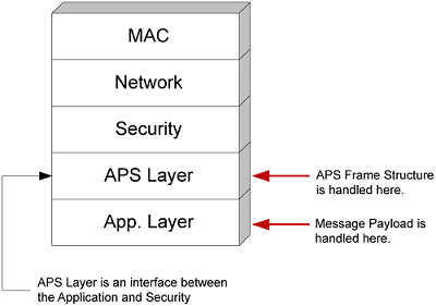
The EmberZNet PRO stack software takes care of most of the low level work required in message handling. The following figure illustrates where the application interacts with the system in message handling. However, while the APS layer handles the APS frame structure, it is still the responsibility of the application to set up the APS header on outbound messages, and to parse the APS header on inbound messages.
Sending Messages#
Three basic types of messages can be sent:
Unicast: sent to a specific node ID based on an address table entry (the node ID can also be supplied manually by the application if necessary)
Broadcast: sent to all devices, all non-sleepy devices, or all non-ZEDs (Zigbee End Devices)
Multicast: sent to all devices sharing the same Group ID
Before sending a message you must construct a message. The message frame varies according to message type and security levels. Since much of the message frame is generated outside of the application, the key factor to be considered is the maximum size of the message payload originating in your application.
The following table shows the detailed API for sending the most common message types.
| EmberZNet API | Application Framework API | Description |
|---|---|---|
| emberSendUnicast ( EmberOutgoingMessageType type, int16u indexOrDestination, EmberApsFrame * apsFrame, EmberMessageBuffer message ) |
emberAfSendUnicast( EmberOutgoingMessageType type, int16u indexOrDestination, EmberApsFrame *apsFrame, int8u messageLength, int8u* message ) |
Sends a unicast message as per the Zigbee PRO specification. |
| emberSendBroadcast ( EmberNodeId destination, EmberApsFrame * apsFrame, int8u radius, EmberMessageBuffer message ) |
emberAfSendBroadcast ( int16u destination, EmberApsFrame *apsFrame, int8u messageLength, int8u* message ) |
Sends a broadcast message as per the Zigbee PRO specification. The message will be delivered to all nodes within radius hops of the sender. A radius of zero is converted to EMBER_MAX_HOPS. |
| emberSendMulticast ( EmberApsFrame * apsFrame, int8u radius, int8u nonmemberRadius, EmberMessageBuffer message ) |
emberAfSendMulticast( int16u multicastId, EmberApsFrame * apsFrame, int8u messageLength, int8u* message ) |
Sends a multicast message to all endpoints that share a specific multicast ID and are within a specified number of hops of the sender. |
Note: Please keep in mind that the online API documentation is more extensive than that shown here. Always refer to the online API documentation for definitive information.
In every case illustrated above, a message buffer contains the message. Normally, the application allocates memory for this buffer (as some multiple of 32 bytes). You can find out dynamically how big this buffer can be, which in turn determines the maximum size of the message to be sent. The function emberMaximumApsPayloadLength(void) returns the maximum size of the payload that the application support sub-layer will accept, depending on the security level in use. This means that:
Constructing your message involves supplying the arguments for the appropriate message type
emberSend...function.Use
emberMaximumApsPayloadLength(void)to determine how big your message can be.Executing the
emberSend...function causes your message to be sent.
Normally, the emberSend... function returns a value. Check the online API documentation for further information.
While the task of sending a message is a bit complex, it is also very consistent. The challenge in designing your application is to keep track of the argument values and the messages to be sent. Some messages may have to be sent in partial segments and some may have to be resent if an error occurs. Your application must deal with the consequences of these possibilities.
Receiving Messages#
Unlike sending messages, receiving messages is a more open-ended process. The application is notified when a message has been received, but the application must decide what to do with it and how to respond to it. Zigbee Application Framework-based applications use a variety of different callback functions devoted to the specific command or response represented by the message, such as emberAfReadAttributesResponseCallback or emberAfDemandResponseLoadControlClusterLoadControlEventCallback. See *UG391:*Zigbee Application Framework Developer's Guide for SDK 6.x and Lower or Zigbee Application Framework Developer’s Guide for SDK 7.0 and Higher for details about how the framework processes incoming messages and about the available callbacks for handling these in your application.
It is also important to note that the stack doesn’t detect or filter duplicate packets in the APS layer. Nor does it guarantee in-order message delivery. These mechanisms need to be implemented by the application.
In the case of the SoC, the stack deals with the mechanics of receiving and storing a message. But in the case of the NCP, the message is passed directly to the host. The host must deal with receiving and storing the message in addition to reacting to the message contents.
In all cases, the application must parse the message into its constituent parts and decide what to do with the information. Note that the application framework, as part of the application, performs most of the message parsing. The application framework does still give the application developer complete flexibility and control over message receive processing. Messages can be generally divided into two broad categories: command or data messages. Command messages involve the operation of the target as a functional member of the network (including housekeeping commands). Data messages are informational to the application, although they may deal with the functionality of a device with which the node is interfaced, such as a temperature sensor.
Acknowledging Messages#
When a message is received, it is good network protocol to acknowledge receipt of the message. This is done automatically in the stack software at the MAC layer with a Link ACK, requiring no action by the application. The following figure shows node A sending a message to node D.
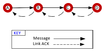
Applications receive a callback when the delivery process completes. The callback indicates success or failure of the delivery based on the receipt or lack of the ACK, either the APS [end-to-end] ACK if requested or the MAC [link] ACK if not. Developers therefore can read the success or failure of the delivery process and optionally retry the delivery at the application level, if desired.
NCP and Host Application Compatibility#
It is very important to ensure that the NCP application has the necessary core functionality so that the host processor can rely upon the NCP to perform its networking functions. For example, if a host application needs to be able to send one type of messages, the NCP must contain support for handling that type of EZSP commands from the host processor.
Compatibility is determined differently, depending on if you are building a custom NCP image or using one of the Silicon Labs pre-built firmware images. If you are building a custom NCP image with the Network Coprocessor Application Framework, then you need to include library components that contain the functionality your host application wants to perform If a host application is receiving a lot of EZSP_ERROR_INVALID_FRAME_ID error values from the NCP, rebuild the image to include the library that is related to these commands.
If instead you are using the prebuilt firmware images, then the process is a simpler. The current prebuilt offerings include all-encompassing NCP images that can properly handle any EZSP frame that is sent from a host built using the Zigbee Application Framework.
The following table is designed to help pair a host application with a suitable NCP application (ZAF = Zigbee Application Framework).
| Host Application | ||
|---|---|---|
| NCP Application ( image name ) | Single Zigbee PRO Network (ZAF) | Dual Zigbee PRO + Zigbee PRO Network (ZAF) |
| Custom NCP application (Network Coprocessor Application Framework) | YES Functionality in the host application must be mirrored with corresponding components in the NCP configuration. | YES Functionality in the host application must be mirrored with corresponding components in the NCP configuration. For multi-network host configurations, the multi-network-library must be included in the NCP configuration. |
| All-encompassing NCP applications ( ncp-spi, ncp-uart ) |
YES | YES |