Zigbee Application Framework Components#
The Zigbee Application Framework contains support for components. A component is an implementation of a piece of functionality within the framework. Components are installed and configured through the Component Editor. Zigbee Application Framework ships with default implementations of many of the ZCL clusters packaged as components. This section describes a subset of these components.
Over-the-Air Upgrade Components#
The Over-the-Air (OTA) Bootload cluster is a large piece of functionality in the Smart Energy 1.1 specification. It involves a number of modules to support software implementations on different platforms and for both the client and server. This section details each of the different pieces and describes their function in the Zigbee Application Framework.
Architecture#
This section explains the architecture of the cluster and where developer code fits into the Zigbee Application Framework.
The Zigbee OTA cluster provides a common way for all devices to have a manufacturer-independent method to upgrade devices in the field. The Zigbee OTA cluster only supports application bootloaders where a device has the capability to download and store the entire image in external storage while still running in the Zigbee network.
The Zigbee OTA cluster defines the protocol by which client devices query for new upgrade images and download the data, and how the server devices manage the downloads and determine when devices shall upgrade after downloading images.
Silicon Labs provides all the cluster code for both client and server to correctly process and respond to all Zigbee OTA messages. In addition, it provides code for managing the stored image(s) and bootloading the target chip.
A number of decisions have to be made about the architecture of the upgrade and how it will be handled. Below are several key questions to answer.
What external storage device will be used for the OTA upgrade image?
Silicon Labs provides a few EEPROM driver implementations as well as a POSIX file system (for UART host only).
If a different driver or method is desired, then this code must be provided.
Does a client device require multiple upgrade files to bootload?
If so, the multiple upgrade files can be co-located within the same Zigbee OTA file transferred OTA. However, this requires a storage device that can hold all the upgrade files at the same time.
The Zigbee OTA cluster also supports requesting multiple files, but the client must manage this.
How will upgrade files be labeled?
Each OTA file has a manufacturer ID, an image type ID, and a version number. Zigbee assigns the value for the manufacturer ID, but the manufacturer controls the other two values, which can be set to whatever values the manufacturer wants. The choice of what values to use depends on the versioning scheme used by the developer and how products from the same manufacturer are differentiated.
Will image signing and verification be used by client devices?
Although the choice to support the Zigbee OTA cluster is optional for SE devices, if devices do support the cluster, then manufacturers must digitally sign upgrade images and their devices must verify the authenticity and integrity of those images.
Manufacturers that use image signing must obtain signing certificates and embed the EUI64s of allowed signers within the software so downloaded images can be validated.
How will bootloading be handled by clients?
Bootloading is device specific, although Silicon Labs provides sample code to bootload both its SOC and NCP chips. But it is likely the developer will have to provide additional specific code to support their own device.
How will the server receive the images to be distributed to clients?
The Zigbee implementation provides a POSIX server that can serve up OTA files that reside on a file system. If the server is an EEPROM-based system, then some other mechanism must be created to transfer the images to the server so they can be served to Zigbee OTA clients.
Generating Zigbee OTA Images#
Silicon Labs provides a tool called Image-builder that can generate correctly formatted Zigbee OTA images. This tool takes in bootloader files (such as a GBL file) and generates the correct format according to the command-line input, as illustrated in the following figure. The tool can also sign the images using the Elliptic Curve Digital Signature Algorithm (ECDSA) signature algorithm as dictated by the Zigbee OTA cluster specification.
For more information on using Image-builder, see Instructions for Using Image-Builder.

Image Signing#
The Zigbee SE Profile requires that OTA files be signed by the manufacturer. Downloaded files must be validated by the OTA client prior to installation. When images are signed, the signer’s certificate is included automatically as a tag in the file and a signature tag is added as the last tag in the file.
The EUI of the authorized signing certificates must be embedded in the client’s current software image so it can validate that only the certificates pertaining to the manufacturer of the device can sign update images.
For development and or test deployments that want to use signing and OTA images a test certificate can be used from the Certicom Test CA to sign images. Image-builder has a test certificate embedded in it for this purpose and, by default, Project Configurator includes the EUI of that test certificate as an authorized signer.
Note: For generation of production images to be shipped to deployed devices, it is highly recommended that manufacturers use their own certificates issued from the Certicom Production CA to sign images and specify only these EUIs as authorized signers.
The certificates and private keys used for signing are the same type as certificates and private keys used by SE devices. However, their use and storage should be handled differently. These are the differences:
Certificates and private keys used for signing should only be used for signing. They should never be put on devices as device-specific certificates and keys. This holds true regardless of whether the device is a test device or a production device.
The EUI used for the signing certificate should NOT be used for any other device or for any other purpose. That EUI should NOT be part of a general pool of EUIs used for production devices.
It is recommended that at least three signing certificates with private keys be generated with three different EUIs. Multiple signing certificates allow for deprecating an expired or compromised private key.
Devices should be set up to accept all of those EUIs as authorized signers of images. If a single key or certificate is compromised, it can be deprecated through a software update and devices will not accept images signed by that entity. In that case, a new signing certificate should be created to replace the compromised one, and subsequent software releases should set it up to be an authorized signer. In the interim, one of the other two alternative signing certificates can be used to sign software updates.
Signer private keys should be stored in a secure location with limited access.
Lastly, it should be noted that mixing production device certificates with a test certificate signer (and vice versa) does not work. In other words, if a device has a production certificate from the Certicom Production CA, then it can only validate images signed with a production certificate. Similarly, devices with test certificates can only accept signers that have certificates issued from the Certicom Test CA.
Component Architecture#
A diagram of the architecture of the OTA components is shown in the following figure.
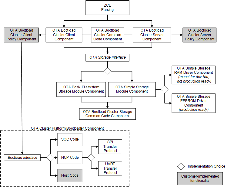
ZCL Framework Core#
This code is provided by the core Zigbee Application Framework and performs the basic parsing and verification of incoming and outgoing messages using the ZCL.
OTA Bootload Cluster Common Code Component#
This component provides common code to the OTA client and server cluster components. It must be enabled if either the OTA Bootload Cluster Server Component or the OTA Bootload Cluster Client Component is enabled. This component has no configurable options.
OTA Bootload Cluster Server Component#
The OTA Server cluster performs the message parsing of OTA Bootload cluster client commands sent to the server and generates server commands sent to the clients. It does not handle storage of the OTA files, but instead relies upon an external module for that support. Its role is simply to validate the incoming messages and generate the correct replies based on its own supported functionality and the OTA specification.
Silicon Labs provides a Zigbee Application Framework component that implements the server cluster.
Options | Description |
|---|---|
Page Request Support | The OTA Server Cluster component can support the optional Page Request feature of the Zigbee OTA cluster. If this option is enabled, the server will answer page requests and send multiple blocks of the download image back to the client. |
OTA Bootload Cluster Server Policy Component#
This module defines how the OTA server reacts when it receives certain requests from the client. The server cluster code calls into this module to ask how certain operations should be handled. For example, when a client is finished downloading a file, it sends an upgrade end request to the server to ask when it can upgrade to the new image. The server cluster code parses the message and then calls into the server policy code to determine the answer.
Other examples of policies handled by this module include how to respond when a query for the next OTA image to download is received and how to respond when receiving an image block request.
This component has no configurable options.
OTA Bootload Cluster Client Component#
The OTA client cluster performs the message parsing of OTA Bootload cluster server commands sent to the client and generation of client commands sent to the server. It does not handle storage of the OTA files, but instead relies upon an external module for that support. Its role is simply to validate the incoming messages and generate the correct replies based on its own supported functionality.
Silicon Labs provides a Zigbee Application Framework component that implements the client cluster. The component has optional support for the signature verification feature. When enabled, this checks the ECDSA signature on received OTA files before generating the upgrade end message sent back to the server.
Options | Description |
|---|---|
Query OTA Server Delay (minutes) | How often the client queries the OTA server for a new upgrade image. |
Download Delay (ms) | How often a new block of data (or page) is requested during a download by the client. A value of 0 means the client requests the blocks (or pages) as fast as the server responds. |
Download Error Threshold | How many sequential errors cause a download to be cancelled. |
Upgrade Wait Threshold | How many sequential, missed responses to an upgrade end request cause a download to be applied anyway. |
Server Discovery Delay (minutes) | How often a client looks for an OTA server in the network when it did not successfully discover one. Once a client discovers the server, it remembers that server until it reboots. |
Run Upgrade Delay Request (minutes) | How often the client will ask the server to apply a previously downloaded upgrade when the server has previously told the client to wait. |
Use Page Request | Selecting this option causes the client device to use an OTA Page Request command to ask for a large block of data all at once, rather than use individual image block requests for each block. If the server does not support this optional feature, then the client falls back to using individual block requests. |
Page Request Size | The size of the page to request from the server. |
Page Request Timeout (seconds) | The length of time to wait for all blocks from a page request to come in. After this time has expired, missed packets are requested individually with image block requests. |
Signature Verification Support | This requires all received images to be signed with an ECDSA signature and verifies the signature once the download has completed. If an image fails verification, it is discarded. This verification occurs prior to any custom verification that might verify the contents. |
Verification Delay (ms) | This controls how often an ongoing verification process executes. When signature verification is enabled, this controls how often digest calculation is executed. Digest calculation can take quite a long time for an OTA image. Other processing for the system may be deemed more important and therefore Silicon Labs adds delays between calculations. This also controls how often custom verification written by the application developer is executed. A value of 0 means the calculations run to completion. |
Image Signer EUI64 0 | The big endian EUI64 address of a device authorized to sign OTA images for this client. A value of all 0s is ignored. |
Image Signer EUI64 1 | The big endian EUI64 address of a device authorized to sign OTA images for this client. A value of all 0s is ignored. |
Image Signer EUI64 2 | The big endian EUI64 address of a device authorized to sign OTA images for this client. A value of all 0s is ignored. |
Note: The default value for the Image Signer EUI64 0 option is the EUI64 of the test certificate embedded within the Image-builder provided by Silicon Labs. Using this default will allow customers to test image signing and verification prior to obtaining production signing certificates from Certicom.
OTA Bootload Cluster Client Policy Component#
This module controls the OTA cluster client’s behavior. It dictates what image information it uses in the query, what custom verification of the image is done by the device, and what happens when the client receives a command to upgrade to the new image.
Silicon Labs provides a component that provides a simple implementation of the OTA client policy.
Note: The Manufacturer ID is not set in this component, but in the top tab of the Zigbee Cluster Configurator.
Options | Description |
|---|---|
Image Type ID | The device's OTA image identifier used for querying the OTA server about the next image to use for an upgrade. |
Firmware Version | The device's current firmware version used when querying the OTA server about the next image to use for an upgrade. |
Hardware Version | Devices may have a hardware version that limits what images they can use. OTA images may be configured with minimum and maximum hardware versions on which they are supported. If the device is not restricted by hardware version, then this value should be 0xFFFF. |
Perform EBL Verification (SOC only) | This option uses the application bootloader routines to verify the EBL image after signature verification passes. |
OTA Storage Components#
The OTA cluster requires a storage device for files received by the OTA clients or served up by the OTA server. This storage varies based on the device’s hardware and design. Therefore, this functionality is separated from the core cluster code and accessed through a set of APIs. The interface supports managing multiple files, retrieving arbitrary blocks of data from the files, and performing basic validation on the file format.
Silicon Labs currently provides two main components that implement the OTA storage module, the OTA Storage POSIX Filesystem component and the OTA Simple Storage component.
OTA Storage POSIX File System Component#
This implementation uses a POSIX file system as the storage module to store and retrieve data for OTA files. It can handle any number of files. This component is used with an EZSP-based platform (such as EFR32 NCP) where the host is connected to the NCP through UART. This component has no configurable options.
OTA Simple Storage Module Component#
This implementation provides a simple storage module that stores only one file. It uses an OTA storage driver to perform the actual storage of the data in a hardware or software device accessible by the OTA cluster code. When enabled, the developer must also select either the OTA Simple Storage RAM Driver Component or the OTA Simple Storage EEPROM Driver Component.
This component can be used by either an EZSP- or an SOC-based platform. This component has no configurable options.
OTA Simple Storage RAM Driver Component#
This driver provides a RAM storage device for storing files. It is intended only as a test implementation for development on WSTKs; it is not intended as production ready code. Prior to integrating external storage hardware into a device, this driver can be useful for examining the basic behavior of the OTA cluster. The storage device has a pre-built OTA image already in place that can be used for downloading but does not actually perform an upgrade. This component has no configurable options.
OTA Simple Storage EEPROM Driver Component#
This driver uses the platform routines to read and write data from an EEPROM. For SOC platforms, this module handles the details of re-mapping the image so that it can be read by the bootloader. Existing bootloaders require that the GBL header be the first bytes at the top the storage device so the code must relocate the OTA header to another location while at the same time providing an interface to the storage code that accesses the OTA file in a linear manner.
The following figure illustrates a change in the OTA image on disk.

Options | Description |
|---|---|
SOC Bootloading Support | This option enables bootloading support for SOC devices. When enabled, it will re-map the OTA image file so that the bootloader data is at the top of the EEPROM and therefore can be accessed by all existing Ember bootloaders. It requires that the bootloader portion of the image is the first TAG in the file. The OTA storage starting offset should be 0 when this is enabled. |
Frequency for Saving Download Offset to Non-Volatile Memory (bytes) | How often the current download offset is stored to NVM, in bytes. If set to 0, it will always be written to NVM. |
OTA Storage Start Offset | The starting offset for the OTA image storage location in the NVM. |
OTA Storage End Offset | The last offset for the OTA image storage location in the NVM. |
EEPROM Device Read-modify-write Support | This checkbox indicates whether the underlying EEPROM storage driver has support for read-modify-write, where a portion of a page of flash can be rewritten without erasing the entire page. If the driver requires a page erase before writing any data, this box should not be selected. Before EmberZNet 4.6.2 read-modify-write support was required by the underlying flash driver. EmberZNet 4.6.2 introduced the ability to use parts where a page-erase is required. When designing software for the development boards this checkbox should remain selected because the EEPROM parts require read-modify-write support. |
OTA Bootload Cluster Storage Common Code Component#
This component provides code common to all the OTA storage components and must be enabled when one of those components is enabled. This component has no configurable options.
OTA Cluster Platform Bootloader Component#
When the client has a completed file downloaded and ready to upgrade, it waits for a command from the server to apply the upgrade. Upon receipt of the command to upgrade, the OTA client cluster code calls into the OTA client policy code to perform the next steps to apply the upgrade.
Silicon Labs provides a single component to handle bootloading. The behavior differs depending on the platform on which it is being used. The OTA Client Policy component calls into this component to perform the actual bootloading.
For the SoC, the bootload code simply calls the platform routine to execute the application bootloader. The application bootloader then reads from the data stored in external EEPROM, copies that data into the chip’s internal flash, and then reboots.
For the NCP, Silicon Labs provides an implementation that bootloads the NCP through serial UART or SPI bus. This implementation works only with the Ember NCP bootloader provided as part of the EZSP NCP firmware delivery. The implementation executes the bootloader on the NCP, transfers the file from the storage device on the host to the NCP by XModem, then reboots the NCP.
For the host, developers are expected to write their own code for bootloading a host system connected to an NCP.
OTA Cluster Command Line Interface#
Client Commands#
Command | Description |
|---|---|
zcl ota client printImages | Prints all images that are stored in the OTA storage module along with their index. |
zcl ota client info | Prints the Manufacturer ID, Image Type ID, and Version information that are used when a query next image is sent to the server by the client. |
zcl ota client status | Prints information on the current state of the OTA client download. |
zcl ota client verify <index> | Performs signature verification on the image at the specified index. |
zcl ota client bootload <index> | Bootloads the image at the specified index by calling the OTA bootload callback. |
zcl ota client delete <index> | Deletes the image at the specified index from the OTA storage device. |
zcl ota client start | Starts the OTA client state machine. The state machine discovers the OTA server, queries for new images, download the images, and waits for the server command to upgrade. |
zcl ota client stop | Stops the OTA client state machine. |
zcl ota client page-request <boolean> | Dynamically enables or disables the use of page request if the client turned on support in Project Configurator. By default, if the client enabled page request support in Project Configurator, then the client uses the page request command when downloading a file. |
zcl ota client block-test | Test harness command. Sends an invalid block request to the client’s previously discovered OTA server to verify that the server sends back the correct command. |
Server Commands#
| Command | Description |
|---|---|
| zcl ota server printImages | Prints all images that are stored in the OTA storage module along with their index. |
| zcl ota server policy print | Prints the policies used by the OTA Server Policy component. |
| zcl ota server delete <index> | Deletes the image at the specified index from the OTA storage device. |
| zcl ota server policy query <int> |
Sets the policy used by the OTA Server Policy component when it receives a query request from the client. The policy values are:
|
| zcl ota server policy blockRequest <int> |
Sets the policy used by the OTA Server Policy component when it receives an image block request. The policy values are:
|
| zcl ota server policy upgrade <int> |
Sets the policy used by the OTA Server Policy component when it receives an upgrade end request. The policy values are:
|
|
zcl ota server notify <dest> <payload type> <jitter> <manuf-id> <device-id> <version> |
This command sends an OTA Image Notify message to the specified destination indicating a new version of an image is available for download. The payload type field values are:
|
| zcl ota server page-req-miss <modulus> | Test harness command. Sets a module’s value that tells the OTA server to artificially skip certain image block responses sent in response to an image page request. This simulates missed blocks that the client will have to request later after the page request has completed. If the number of the block sent by the server is a multiple of the modulus value, then it will be skipped. |
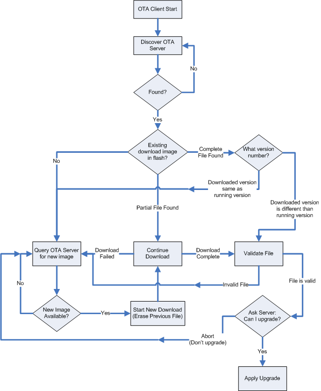
OTA Client State Machine#
The following figure illustrates how the OTA Bootload Cluster client component code will behave from start to finish.
Example Client and Server Setup#
Over-the-Air Bootload Server and Client Setup for Zigbee SDK 7.0 and Higherdescribes a complete client and server setup using plugins and Silicon Labs development kits.
Reporting Component#
ZCL reporting can be setup on a device when the device is required to periodically send out reports. ZCL reports rely on bindings. Each report is an asynchronous message sent out from the reporting device, when a local ZCL attribute has changed, to corresponding entries in the binding table. Either the node sending the reports, the node receiving the reports, or another third-party configuration device may create the binding table entry(s) on the reporting node. This component supports both requesting reports from another device and sending out attribute reports when the device has been configured to do so. If the application will receive reports from multiple sources, the device should be configured as a concentrator.
Reporting Command Line Interface#
The Zigbee Application Framework provides CLI commands for creating and managing reporting table entries directly on the device, requesting reports from another device, and configuring device to send out reports from another device.
Local Commands#
plugin reporting print: Print the report table.
plugin reporting clear: Print the report table.
plugin reporting remove [index:1]: Remove an entry from the report table.
index: Index of the report to be removed (1 byte).
plugin reporting add [endpoint:1] [clusterId:2] [attributeId:2] [mask:1] [minInterval:2] [maxInterval:2] [reportableChange:4]: Add a new entry to the report table.
endpoint: Local endpoint from which the attribute is reported (1 byte).
clusterId: Cluster where the attribute is located (2 bytes).
attributeId: ID of the attribute being reported (2 bytes).
mask: 0 for client-side attributes or 1 for server-side attributes (1 byte).
minInterval: Minimum reporting interval, measured in seconds (2 bytes).
maxInterval: Maximum reporting interval, measured in seconds (2 bytes).
reportableChange: Minimum change to the attribute that will result in a report being sent (4 bytes).
Remote Commands#
zcl global report [endpoint:1] [clusterId:2] [attributeId:2] [direction:1]: Creates a report with the specified cluster, attribute, and server/client direction.
endpoint: Source endpoint ID to read from (2 bytes).
clusterId: Cluster ID to read from (2 bytes).
attributeId: Attribute ID to read from (2 bytes).
direction: 0 for client-to-server, 1 for server-to-client (1 byte).
zcl global report-read [cluster:2] [attributeId:2] [direction:1]: Creates a global read reporting command for the associated cluster, attribute, and server/client direction.
cluster: Cluster ID to read from (2 bytes).
attributeId: Attribute ID to read from (2 bytes).
direction: 0 for client-to-server, 1 for server-to-client (1 byte).
zcl global send-me-a-report [cluster:2] [attributeId:2] [dataType:1] [minReportTime:2] [maxReportTime:2] [reportableChange:-2147483648]: creates a global send me a report command for the associated values.
cluster: Cluster ID of the requested report (2 bytes).
attributeId : Attribute ID for requested report (2 bytes).
datatype: Zigbee type value for the requested report (1 byte).
minReportTime: Minimum number of seconds between reports (2 bytes).
maxReportTime: Maximum number of seconds between reports (2 bytes).
reportableChange: Amount of change to trigger a report.
zcl global expect-report-from-me [cluster:2] [attributeId:2] [timeout:2]: Create an expect-report-from-me message with associated values.
cluster: Cluster ID of the requested report (2 bytes).
attributeid: Attribute ID for requested report (2 bytes).
timeout: maximum amount of time between reports.
Reporting Connection Setup through CLI#
The following CLI example assumes these application configurations:
The report sender application should implement the Basic Cluster on endpoint 6.
The report receiver application should implement the Basic Cluster on endpoint 1.
Both applications should have debugging messages turned on. It is also assumed that both devices have joined the same network with the report sender node as the creator of the network.
Clear all bindings on the sender node since reports are sent via bindings.
report_sender_cli> option binding-table clearRequest reports of the application version (cluster 0x0000, attribute 0x0001) of the sender to receiver node by receiving node.
report_receiver_cli> zcl global send-me-a-report 0x0000 0x0001 0x20 10 20 {00} report_receiver_cli> send 0 1 6Following outputs should be observed:
report_sender_cli> CFG_RPT: (Basic) - direction:00, attr:0000 type:20, min:000A, max:0014 change:00 report_receiver_cli> CFG_RPT_RESP: (BASIC) – status: 00After successfully send the report request (status – 00), an actual report can be read by the receiver node using following command:
report_receiver_cli> zcl global report-read 0x0000 0x0000 0x00 report_receiver_cli> send 0 1 6Following outputs should be observed:
report_receiver_cli> READ_RPT_CFG_RESP: (Basic) - status:00, direction:00, attr:0000 type:20, min:000A, max:0014 change:00Find node field ID or IEEEAddr from receiver node.
report_receiver_cli> infoCreate binding on sending node to start sending reports to the receiver.
report_sender_cli> option binding-table set 0 0x0000 0x06 0x01 {EUI64 node ID from previous step}Following outputs should be observed:
“set bind 0: 0x00”The receiver node should start getting reports as follow:
report_receiver_cli> RPT_ATTR: (Basic) - attr:0000 type:20, val:01Cancel report (by setting the maximum interval to 0xFFFF)
report_receiver_cli> zcl global send-me-a-report 0x0000 0x0000 0x20 0x0000 0xFFFF {00} report_receiver_cli> send 0 1 6Following outputs should be observed:
report_sender_cli> CFG_RPT: (Basic) - direction:00, attr:0000 type:20, min:0000, max:FFFF change:00 report_receiver_cli> CFG_RPT_RESP: (Basic) – status: 00
Reporting for External Attributes#
The Zigbee Application Framework automatically notifies the component whenever attributes that it manages are changed. Customers who use external attributes must notify the Reporting component when those attributes change. Failure to notify the component will result in incorrect reporting behavior. Any applications that will be reporting external attributes must call sl_zigbee_af_reporting_attribute_change_cb whenever external attributes change.