Pin Tool#
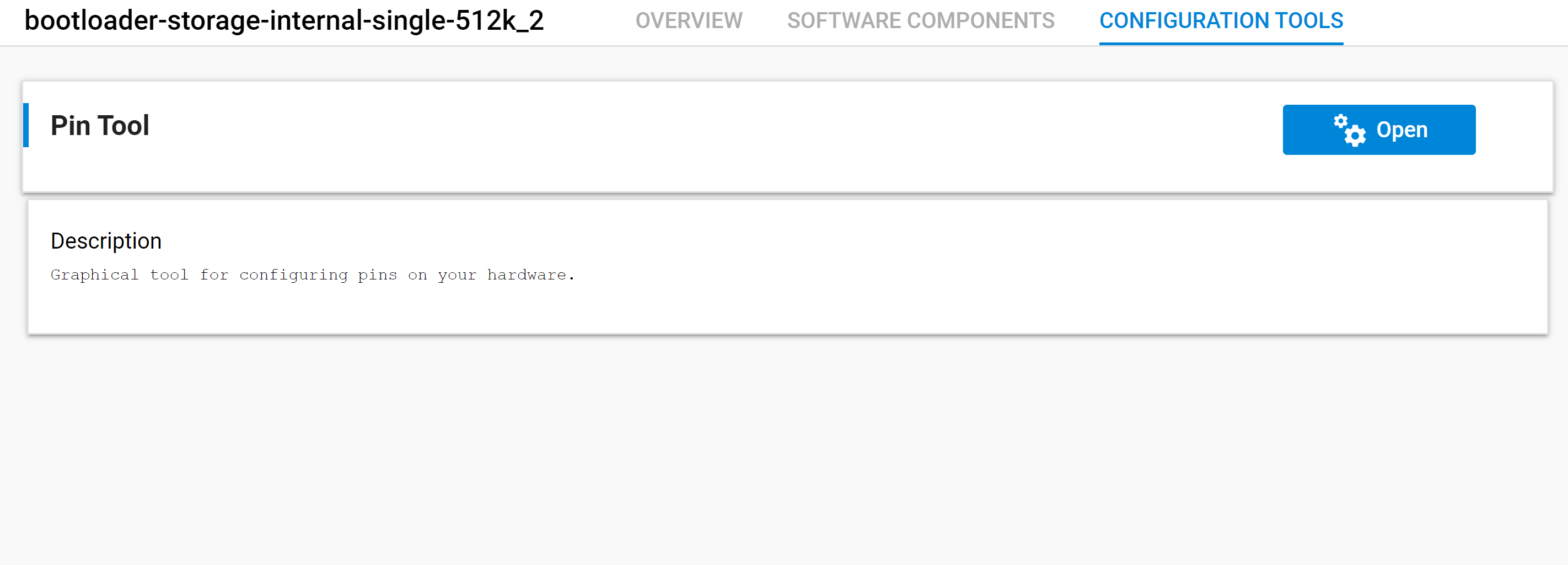
In contrast to the AppBuilder workflow, Simplicity Studio v5 offers the Pin Tool configuration tool, which can be used to configure the various pins of the MCU used in the project. Pin Tool can be used in standalone mode through the tile on the Configuration Tools tab.

Pin Tool-related configuration is also available through the Component Editor of all applicable configurable components, making it a one-stop solution for configuring pin details and setting user configuration details. Following is the list of configurable components that also include Pin Tool configuration (wherever applicable) in their configuration wizard.
Configurable Component | Configuration Options |
|---|---|
UART XMODEM | Menu Idle Timeout |
Bootloader Core | All options that were available for the bootloader plugin are now available in the Bootloader Core component. Options include: Enable Secure Boot, Enable certificate support, Prevent bootloader write/erase, etc |
Bootloader UART/EUART Driver | Configuration options include: USART settings, USART peripheral, Serial VCOM Enable/Disable |
Bootloader SPI Controller USART/EUSART Driver | Configuration options include: Frequency, Peripheral and SPI Port Settings |
Bootloader SPI Peripheral USART/EUSART Driver | Configuration options include: Tx Buffer Size, Rx Buffer Size, Peripheral and Port Settings |
Bootloader Storage Slot Setup | Supports configuration of storage slot (start addresses and slot lengths) up to a maximum of 3 slots |
Common Storage/Common Storage (single storage slot only) | Configuration options include: Start address of bootload info |
Internal Storage | Configuration options include: Enable DMA based MSC Write, DMA channel to reserve |
SPI Flash Storage | Enables configuration of the list of SPI flash devices that must be enabled in the bootloader image |
Debug | Enable/disable Debug prints/asserts |
EZSP GPIO Activation | Configuration options include: Properties of SPI NCP, WAKE INT Pin, HOST INT Pin |
GPIO Activation | Configuration options include: Properties of Bootloader entry, Button Pin configuration |
The configuration options of any installed configurable component can be accessed by clicking Configure. Refer to section 2 Project Creation for more details on the Component Editor.
As an example, in the following procedure the Bootloader SPI Controller USART Driver is configured using the Component Editor and the pin configuration is verified using the Pin Tool.
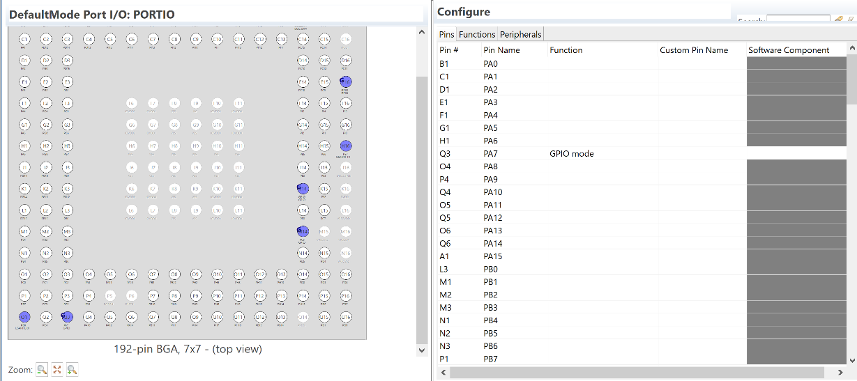
Pin Tool configuration before installing the SPI Controller component. The device used for this example is the EFM32GG11 Giant Gecko Starter Kit board (BRD2204A Rev B00).
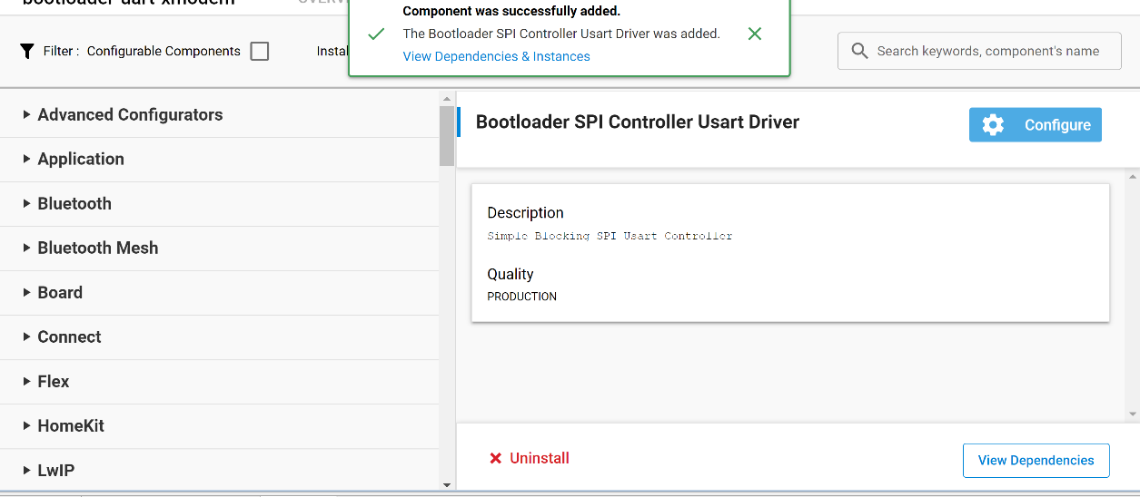
Install the Bootloader SPI Controller USART driver component.
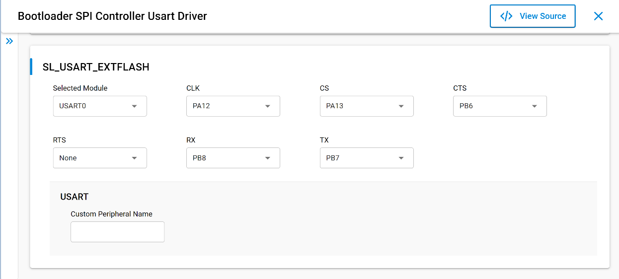
Click Configure to open the Component Editor and configure the USART peripheral as shown.
Open the Pin Tool.
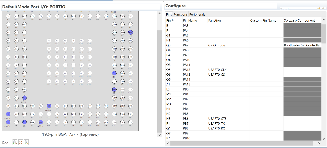
The pin configurations are shown. Notice that pins PA12, PA13, PB6, PB7, and PB8 are reserved for USART0.