Getting Started with the BGM220 Explorer Kit#
The BGM220 Explorer Kit (part number: BGM220-EK4314A) is focused on rapid prototyping and IoT concept creation around Silicon Labs BGM220P module.
Kit Overview#
The kit features USB interface, on-board J-Link debugger, one user LED/button and support for hardware add-on boards via a mikroBus socket, and a qwiic connector.
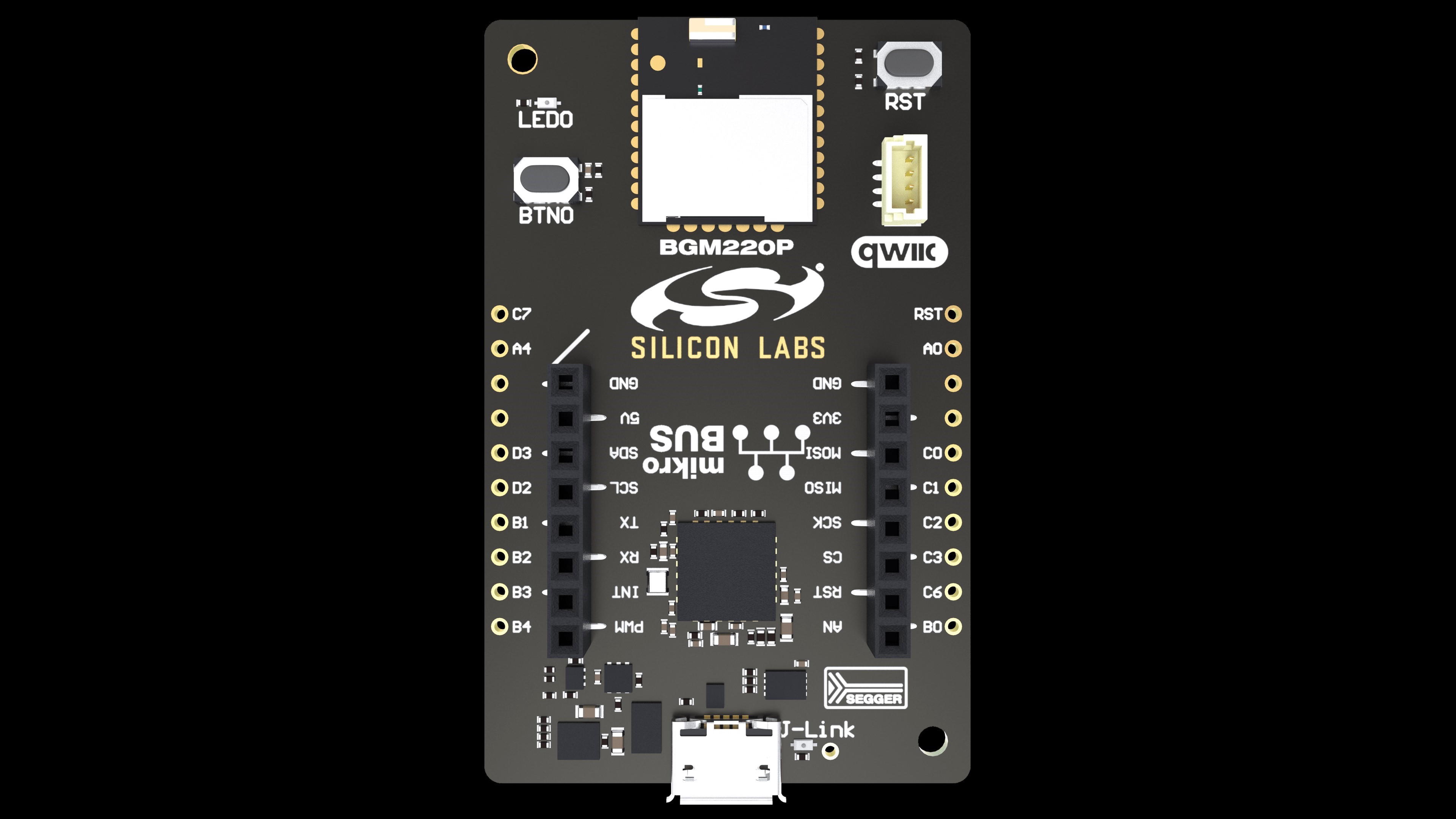
The hardware add-on support allows developers to create and prototype applications using a virtually endless combination of off-the-shelf boards from mikroE, sparkfun, AdaFruit, and Seeed Studios. The boards from Seeed Studios feature a connector, which is pin compatible with the qwiic connector but mechanically incompatible and it requires an adaption cable or board.
Testing the Bluetooth Demos#
The Bluetooth SDK comes with pre-built demos that can be directly flashed into this kit and tested using a smartphone running the EFR Connect mobile app (Android, iOS):
SoC iBeacon
NCP Empty
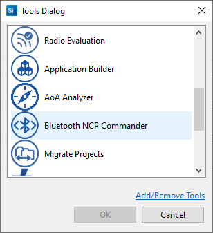
The iBeacon can be tested with EFR Connect as documented in Getting Started with the WSTK. NCP Empty can be tested with NCP Commander, which can be launched via the Tools dialog in Simplicity Studio 5.
GitHub Examples#
Silicon Labs applications_examples GitHub repository contains additional examples that can run on the BGM220 Explorer Kit. Some of them leverage 3rd party add-on boards and they are typically found in the bluetooth_applications repository.
Porting Code from mikroSDK and Arduino#
If using a mikroE click board, ready made examples are on your specific mikroE click board Web page that typically reside in mikroE's libstock and/or GitHub. Those examples are using the mikroSDK, which provides abstraction to the supported hardware kits provided by mikroE.
If using a board from sparkfun, Adafruit, or Seeed Studios, they typically have examples for the Arduino IDE, which run on some of their own controller boards that are supported by the Arduino platform.
Those examples will not run out of the box on the BGM220 Explorer Kit, but with a small amount of effort they can be easily ported by using the guide below, which maps mikroSDK and Arduino APIs for UART/SPI/I2C/GPIO functionality into the Silicon Labs platform equivalents.
Whether porting from mikroSDK or Arduino, EMLIB and Platform Drivers/Services contain the most useful Silicon Labs APIs. For corresponding documentation, see below:
EMLIB - a low level peripheral driver library for all Silicon labs EFM32 and EFR32 device families
Platform Drivers - a higher level driver layer built on top of EMLIB. EMDRV abstracts some aspects of peripheral initialization and use but is more limited in peripheral coverage than EMLIB.
Additionally, Silicon Labs' Peripheral Examples on GitHub are a good resource for simple demonstration of peripheral control using EMLIB.
mikroSDK Porting Guide#
The mikroE ecosystem of click boards from MikroElektronika are typically supported by a collection of driver modules and example code built upon the mikroSDK. These click boards feature a mikroBUS connector for connection to a host board and can include connections for power (3.3 V, 5 V, GND), communications (UART, SPI, and/or I2C), and assorted other functions (GPIO, PWM, INT).
The mikroSDK is a framework that provides abstraction for the communication and GPIO functions of the mikroE click boards by wrapping vendor-specific functions in a common API framework to accomplish these tasks that is portable across a wide range of host devices. The microSDK is therefore ported to a new device via the assignment of function pointers and other device-specific configuration options. At this time, there is no official mikroSDK port for Silicon Labs devices.
Note: The goal of this configuration guide is not to instruct the user on how to port the mikroSDK to the BGM220 or other Silicon Labs devices, but instead to introduce the user to the spectrum of Silicon Labs' native APIs and how to use these APIs instead of the mikroSDK.
There is currently a wide selection of mikroE click accessory boards to facilitate product development with devices such as sensors, display/LEDs, storage, interface, and HMI. Some of these boards are shown below.
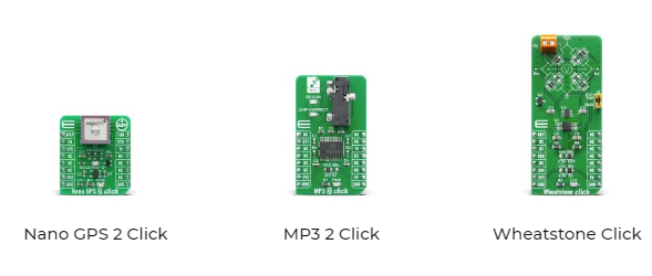
Using the mikroBUS-compatible socket included on the Explorer Kit BGM220, these boards can be used with the BGM220 as the host controller via the pin functions connecting the mikroBUS socket to the BGM220.
When porting mikroE click examples to the Silicon Labs platform, it is important to understand that interaction between the host controller and the click board is accomplished using a subset of UART, I2C, SPI, GPIO, analog, PWM, or interrupt. Pins for each function are allocated between the BGM220 and the mikroBUS connector, as shown below.
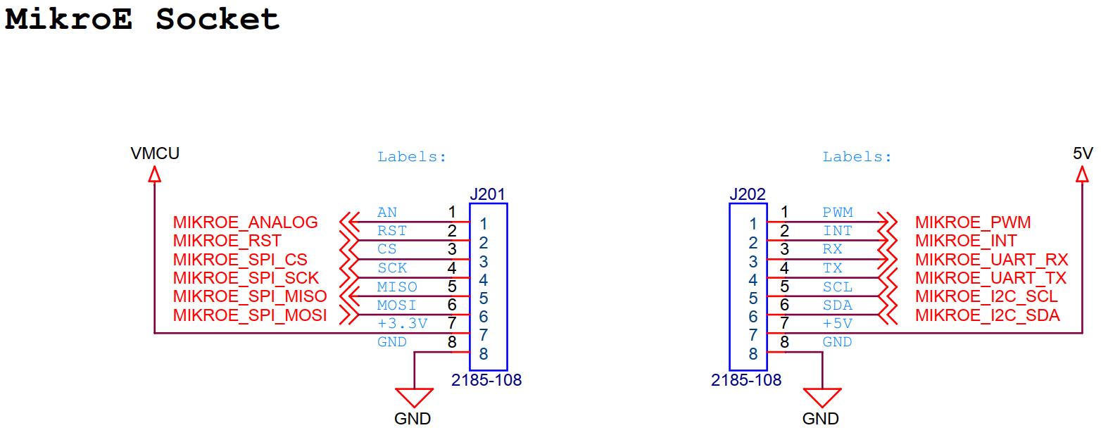
MikroE Socket Signal | MikroE Socket Pin | BGM220 Pin or Board Connection |
|---|---|---|
MIKROE_ANALOG | J201.1 | PB00 |
MIKROE_RST | J201.2 | PC06 |
MIKROE_SPI_CS | J201.3 | PC03 |
MIKROE_SPI_SCK | J201.4 | PC02 |
MIKROE_SPI_MISO | J201.5 | PC01 |
MIKROE_SPI_MOSI | J201.6 | PC00 |
3V3 | J201.7 | VMCU - BGM220P voltage domain |
GND | J201.8 | GND |
MIKROE_PWM | J202.1 | PB04 |
MIKROE_INT | J202.2 | PB03 |
MIKROE_UART_RX | J202.3 | PB02 |
MIKROE_UART_TX | J202.4 | PB01 |
MIKROE_I2C_SCL | J202.5 | PD02 |
MIKROE_I2C_SDA | J202.6 | PD03 |
+5 V | J202.7 | +5 V - Board USB voltage |
GND | J202.8 | GND |
Note: Knowledge of the pin mapping shown above combined with use of Silicon Labs' native APIs, as shown below, enable a user to port existing click examples to the Explorer Kit BGM220 by substituting Silicon Labs API calls for mikroSDK and click driver API calls.
The following sections cover four main categories of API-enabled interactions between a host device (BGM220P in this case) and a click board: GPIO, SPI, I2C, and UART. Note that the functions and structures presented here correspond to elements of the core mikroHAL and mikroBUS APIs of the mikroSDK and their closest Silicon Labs counterparts. Many click boards have additional libraries and driver files that integrate with these layers to create the mikroE project framework. However, these core elements should help guide users porting to the Silicon Labs platform.
GPIO#
The mikroSDK uses a complex system of function pointers and data structures to initialize a low level GPIO driver layer with initialization, "get," and "set" function pointers for each GPIO pin on the mikroBUS header. This structure is inherited by higher-level driver layers, which use "get" and "set" functions in higher-level wrapper functions.
By contrast, the Silicon Labs APIs for GPIO control, or em_gpio, are straightforward and easy to understand. Generally speaking, firmware should first initialize a pin and set its mode (i.e., input type, output type, and so on) by calling GPIO_PinModeSet(), then use various API calls to control or read the pin state. The following table represents a comparison and possible suggested substitution scheme for using em_gpio in place of the mikroSDK GPIO API.
Note: More em_gpio functions are available in EMLIB. For more information,see the GPIO API Documentation.
API category | mikroBUS/mikroHAL function/API | Description | Corresponding Silicon Labs GSDK/EMLIB Platform API |
|---|---|---|---|
GPIO | T_gpio_setFp T_gpio_obj::gpioGet[12] | Pointers to Get functions | GPIO_PinOutGet(), GPIO_PinInGet() |
T_gpio_setFp T_gpio_obj::gpioSet[12] | Pointers to Set functions | GPIO_PinOutSet(), GPIO_PinOutClear(), GPIO_PinOutToggle() | |
T_mikrobus_ret mikrobus_gpioInit (T_mikrobus_soc bus, T_mikrobus_pin pin, T_gpio_dir dir) | Function sets GPIO direction. This function also should be used for GPIO availability check. | GPIO_PinModeSet(), GPIO_PinModeGet() | |
void hal_gpioMap(T_HAL_P gpioObj); | Initialization of the GPIO HAL (internal mapping of function pointers and driver/HAL layer initialization) | N/A |
SPI#
As with the mikroSDK GPIO API, the mikroSDK SPI framework relies on vendor-specific function pointers assigned in a configuration layer to provide an interface for SPI communications.
Silicon Labs offers the low-level EMLIB SPI (Synchronous USART) and higher-level EMDRV driver SPIDRV APIs for SPI communication, provided as source code. The suggested substitutions in the following table assume that the host SoC is the SPI central, however EMLIB and SPIDRV offer peripheral SPI functions as well.
When using EMLIB, firmware must separately configure all SPI pins to the proper mode using the EMLIB GPIO functions before using the pins for SPI communications. When using SPIDRV, however, firmware specifies the desired port and pins to use for the SPI bus in the SPIDRV_Init data structure, and configuration of these pins is handled by the SPIDRV_Init() function.
Note: More EMLIB and SPIDRV functions are available than shown here. See em_usart and and SPIDRV API documentation for more information.
API category | mikroBUS/mikroHAL function/API | Description | Corresponding Silicon Labs GSDK/EMLIB Platform API |
|---|---|---|---|
SPI | T_mikrobus_ret mikrobus_spiInit (T_mikrobus_soc bus, const uint32_t *cfg) | Function will initialize SPI peripheral on provided MIKROBUS depending on configuration provided as second argument. | USART_InitSync() or SPIDRV_Init()/SPIDRV_DeInit() |
void hal_spiMap(T_HAL_P spiObj); | Initialization of the SPI HAL (internal mapping of function pointers and driver/HAL layer initialization) | N/A | |
static void hal_spiWrite(uint8_t *pBuf, uint16_t nBytes); | Function should execute write sequence of n bytes. | USART_SpiTransfer() (ignore return value), SPIDRV_MTransmit(), SPIDRV_MTransmitB() | |
static void hal_spiRead(uint8_t *pBuf, uint16_t nBytes); | Function should execute read sequence of n bytes. | USART_SpiTransfer() (read return value, pass dummy data parameter), SPIDRV_MReceive(), SPIDRV_MReceiveB() | |
static void hal_spiTransfer(uint8_t *pIn, uint8_t *pOut, uint16_t nBytes); | Function should execute RW sequence of n bytes | USART_SpiTransfer(), SPIDRV_MTransfer(), SPIDRV_MTransferB(), SPIDRV_MTransferSingleItemB() |
I2C#
As with other mikroSDK modules, the mikroSDK I2C framework relies on vendor-specific function pointers assigned in a configuration layer to provide an interface for I2C communications.
Silicon Labs offers the EMLIB I2C driver em_i2c for firmware control of the I2C interface, which differs slightly in approach from the mikroSDK framework. The em_i2c firmware interface relies on the configuration of the I2C peripheral block and desired transfer parameters using the I2C_Init() and I2C_TransferInit() functions. Management of the I2C transfer state machine handled by repeated calls to I2C_Transfer(), which handles the different phases of the I2C transfer and hardware state machine.
When using EMLIB, firmware must separately configure all I2C pins to the proper mode using the EMLIB GPIO functions before using the pins for I2C communications.
Note: The em_i2c driver library provides additional functions and features beyond those described here. See the em_i2c API documentation for more information.
API category | mikroBUS/mikroHAL function/API | Description | Corresponding Silicon Labs GSDK/EMLIB Platform API |
|---|---|---|---|
I2C | T_i2c_readFp T_i2c_obj::i2cRead | Pointer to I2C Read function | I2C_Transfer() |
T_i2c_restartFp T_i2c_obj::i2cRestart | Pointer to I2C Restart function | I2C_Transfer() | |
T_i2c_startFp T_i2c_obj::i2cStart | Pointer to I2C Start function | I2C_Transfer() | |
T_i2c_stopFp T_i2c_obj::i2cStop | Pointer to I2C Stop function | I2C_Transfer() | |
T_i2c_writeFp T_i2c_obj::i2cWrite | Pointer to I2C Write function | I2C_Transfer() | |
T_mikrobus_ret mikrobus_i2cInit (T_mikrobus_soc bus, const uint32_t *cfg) | Function will initialize I2C peripheral on provided MIKROBUS depending on configuration provided as second argument. | I2C_Init(), I2C_TransferInit() | |
void hal_i2cMap(T_HAL_P i2cObj); | Initialization of the I2C HAL (internal mapping of function pointers and driver/HAL layer initialization) | N/A | |
static int hal_i2cStart(); | This function in the snippet above should execute start condition on the I2C BUS. | I2C_TransferInit(), I2C_Transfer() | |
static int hal_i2cWrite(uint8_t peripheralAddr, uint8_t *pBuff, uint16_t nBytes, uint8_t endMode); | This function in the snippet above should execute write sequence, write the data inside the pBuf and execute “end” or “restart” condition, depending on the endMode argument. | I2C_Transfer() | |
static int hal_i2cRead(uint8_t peripheralAddr, uint8_t *pBuff, uint16_t nBytes, uint8_t endMode); | This function in the snippet above should execute read sequence, and place the data inside the pBuf and execute “end” or “restart” condition, depending on the endMode argument. | I2C_Transfer() |
UART#
In a similar fashion as other mikroSDK API modules, the mikroSDK UART framework relies on vendor-specific function pointers assigned in a configuration layer to provide an interface for UART communications.
Silicon Labs offers the low-level EMLIB UART (asynchronous USART) and higher-level EMDRV driver UARTDRV APIs for UART communication, provided as source code.
When using EMLIB, firmware must separately configure all UART pins to the proper mode using the EMLIB GPIO functions before using the pins for UART communications. When using UARTDRV, however, firmware specifies the desired port and pins to use for the UART bus in the UARTDRV_InitUart_t data structure. Configuration of these pins is handled by the UARTDRV_InitUart() or UARTDRV_InitLeuart() function.
Note: The EMLIB em_usart and EMDRV UARTDRV APIs provide additional functionality and support a wider feature set of the USART peripheral than is described in this porting guide. See the em_usart and UARTDRV API documentation for more information.
API category | mikroBUS/mikroHAL function/API | Description | Corresponding Silicon Labs GSDK/EMLIB Platform API |
|---|---|---|---|
UART | T_mikrobus_ret mikrobus_uartInit (T_mikrobus_soc bus, const uint32_t *cfg) | Function will initialize UART peripheral on MIKROBUS1 and assign proper pointers to click driver. | USART_InitAsync(), UARTDRV_InitUart(), UARTDRV_InitLeuart() and UARTDRV_DeInit() |
void hal_uartMap(T_HAL_P uartObj); | Initialization of the UART HAL (internal mapping of function pointers and driver/HAL layer initialization) | N/A | |
static void hal_uartWrite(uint8_t input); | Write one byte over UART | USART_Tx(), UARTDRV_Transmit(), UARTDRV_TransmitB() | |
static uint8_t hal_uartRead(); | Read one byte over UART | USART_Rx(), UARTDRV_Receive(), UARTDRV_ReceiveB() | |
static uint8_t hal_uartReady(); | USART_StatusGet(), UARTDRV_GetReceiveStatus() and UARTDRV_GetTransmitStatus() |
Arduino Porting Guide#
Many open-source examples, including those designed for use with expansion boards from sparkfun, Adafruit, or Seeed Studios, use the Arduino API. This section provides a basic mapping of some of the Arduino API functions for serial communications and GPIO handling onto suggested or possible replacement calls from the Silicon Labs EMLIB and EMDRV libraries.
Although the Arduino API contains many submodules for different tasks, this guide focuses on Silicon Labs API replacements for GPIO control (Arduino Digital IO API), SPI communications (Arduino SPI API), I2C communications (Arduino Wire API), and UART communications (Arduino Serial and SoftwareSerial APIs).
GPIO (Arduino Digital IO API)#
The Silicon Labs APIs for GPIO control, or em_gpio, provide straightforward and easy to understand functions for GPIO initialization and control. Generally speaking, firmware should first initialize a pin and set its mode (i.e., input type, output type, and so on) by calling GPIO_PinModeSet(), then use various API calls to control or read the pin state. The following table represents a comparison and possible suggested substitution scheme for using em_gpio in place of the Arduino Digital I/O API.
Note: More em_gpio functions are available in EMLIB than shown here. See the em_gpio API documentation for more information.
API category | Arduino function/API | Description | Corresponding Silicon Labs GSDK/EMLIB Platform API |
|---|---|---|---|
GPIO | pinMode() | Configures the specified pin to behave either as an input or an output. | GPIO_PinModeSet(), GPIO_PinModeGet() |
digitalRead() | Reads the value from a specified digital pin, either HIGH or LOW. | GPIO_PinOutGet(), GPIO_PinInGet() | |
digitalWrite() | Write a HIGH or a LOW value to a digital pin. | GPIO_PinOutSet(), GPIO_PinOutClear(), GPIO_PinOutToggle() |
SPI (Arduino SPI API)#
Silicon Labs offers the low-level EMLIB SPI (Synchronous USART) and higher-level EMDRV driver SPIDRV APIs for SPI communication, provided as source code. The suggested substitutions in the following table assume that the host SoC is the SPI central. However, EMLIB and SPIDRV offer SPI functions as well.
When using EMLIB, firmware must separately configure all SPI pins to the proper mode using the EMLIB GPIO functions before using the pins for SPI communications. When using SPIDRV, however, firmware specifies the desired port and pins to use for the SPI bus in the SPIDRV_Init data structure. Configuration of these pins is handled by the SPIDRV_Init() function.
Note: More EMLIB and SPIDRV functions are available than shown here. See the em_usart and and SPIDRV API documentation for more information.
API category | Arduino function/API | Description | Corresponding Silicon Labs GSDK/EMLIB/EMDRV Platform API |
|---|---|---|---|
SPI | SPISettings | The SPISettings object is used to configure the SPI port for your SPI device. All 3 parameters are combined to a single SPISettings object, which is given to SPI.beginTransaction() | USART_InitSync_TypeDef Struct |
begin() | Initializes the SPI bus by setting SCK, MOSI, and SS to outputs, pulling SCK and MOSI low, and SS high. | USART_InitSync() with GPIO_PinModeSet() OR SPIDRV_Init() | |
end() | Disables the SPI bus (leaving pin modes unchanged). | USART_Enable() with parameter enable = false | |
beginTransaction() | Initializes the SPI bus using the defined SPISettings. | USART_InitSync() with GPIO_PinModeSet() OR SPIDRV_Init() | |
endTransaction() | Stop using the SPI bus. Normally, this is called after de-asserting the chip select, to allow other libraries to use the SPI bus. | USART_Enable() with parameter enable = false, USART_Reset(), and GPIO_PinModeSet() OR SPIDRV_DeInit() | |
setBitOrder() | Sets the order of the bits shifted out of and into the SPI bus, either LSBFIRST (least-significant bit first) or MSBFIRST (most-significant bit first). | set by "msbf" element of USART_InitSync_TypeDef structure and passed to USART_InitSync(); OR set by "bitOrder" element of SPIDRV_Init structure and passed to SPIDRV_Init() | |
setClockDivider() | Sets the SPI clock divider relative to the system clock. Depricated for Arduino?? | use USART_BaudrateSyncSet(), USART_InitSync(), SPIDRV_Init() | |
setDataMode() | Sets the SPI data mode: that is, clock polarity and phase. Deprecated for Arduino?? | set by "clockMode" element of USART_InitSync_TypeDef structure and passed to USART_InitSync(); OR set by "clockMode" element of SPIDRV_Init structure and passed to SPIDRV_Init() | |
transfer() | SPI transfer is based on a simultaneous send and receive: the received data is returned in receivedVal (or receivedVal16). In case of buffer transfers the received data is stored in the buffer in-place (the old data is replaced with the data received). | USART_SpiTransfer(), SPIDRV_MTransfer(), SPIDRV_MTransferB(), SPIDRV_MTransferSingleItemB() | |
usingInterrupt() | If your program will perform SPI transactions within an interrupt, call this function to register the interrupt number or name with the SPI library. This allows SPI.beginTransaction() to prevent usage conflicts. Note that the interrupt specified in the call to usingInterrupt() will be disabled on a call to beginTransaction() and re-enabled in endTransaction(). | use USART_IntEnable() and USART_IntDisable() | |
shiftOut() | Bit bang (software) SPI TX. | USART_SpiTransfer(), SPIDRV_MTransfer(), SPIDRV_MTransferB(), SPIDRV_MTransferSingleItemB() | |
shiftIn() | Bit bang (software) SPI RX. | USART_SpiTransfer() (read return value, pass dummy data parameter), SPIDRV_MReceive(), SPIDRV_MReceiveB() |
I2C (Arduino Wire API)#
Silicon Labs offers the EMLIB I2C driver (em_i2c) for firmware control of the I2C interface, which differs slightly in approach from the Arduino Wire API. The em_i2c firmware interface relies on the configuration of the I2C peripheral block and desired transfer parameters using the I2C_Init() and I2C_TransferInit() functions. Management of the I2C transfer state machine is then handled by repeated calls to I2C_Transfer(), which handles the different phases of the I2C transfer and hardware state machine.
When using EMLIB, firmware must separately configure all I2C pins to the proper mode using the EMLIB GPIO functions before using the pins for I2C communications.
Note: The em_i2c driver library provides additional functions and features beyond those described here. See the em_i2c API documentation for more information.
API category | Arduino function/API | Description | Corresponding Silicon Labs GSDK/EMLIB Platform API |
|---|---|---|---|
I2C | begin() | Initiate the Wire library and join the I2C bus as a central or peripheral. This should normally be called only once. | I2C_Init() |
requestFrom() | Used by the central to request bytes from a peripheral device. The bytes may then be retrieved with the available() and read() functions. | I2C_TransferInit() | |
beginTransmission() | Begin a transmission to the I2C device with the given address. Subsequently, queue bytes for transmission with the write() function and transmit them by calling endTransmission(). | I2C_TransferInit() | |
endTransmission() | Ends a transmission to a device that was begun by beginTransmission() and transmits the bytes that were queued by write(). | I2C_Transfer() | |
write() | Writes data from a peripheral device in response to a request from a central, or queues bytes for transmission from a central to peripheral device (in-between calls to beginTransmission() and endTransmission()). | I2C_Transfer() | |
available() | Returns the number of bytes available for retrieval with read(). This should be called on a central device after a call to requestFrom() or on a inside the onReceive() handler. | N/A | |
read() | Reads a byte that was transmitted from a peripheral device to a central after a call to requestFrom() or was transmitted from a central to a . read() inherits from the Stream utility class. | I2C_Transfer() | |
SetClock() | This function modifies the clock frequency for I2C communication. I2C peripheral devices have no minimum working clock frequency, however 100KHz is usually the baseline. | I2C_BusFreqSet(), I2C_BusFreqGet() | |
onReceive() | Registers a function to be called when a device receives a transmission from a central. | use I2C_IntEnable(), I2C_IntDisable(), I2C_IntGet(), I2C_IntClear(), I2C_IntGetEnabled(), I2C_IntSet(), and I2C ISR to manage I2C interrupts, if used | |
onRequest() | Register a function to be called when a central requests data from this peripheral device. | use I2C_IntEnable(), I2C_IntDisable(), I2C_IntGet(), I2C_IntClear(), I2C_IntGetEnabled(), I2C_IntSet(), and I2C ISR to manage I2C interrupts, if used |
UART (Arduino Serial and SoftwareSerial APIs)#
Silicon Labs offers the low-level EMLIB UART (asynchronous USART) and higher-level EMDRV driver UARTDRV APIs for UART communication, provided as source code. Additionally, Silicon Labs offers a higher-level driver called RetargetIo that re-targets some standard IO functions such as printf and may be useful for replacement of some Arduino Serial and SoftwareSerial functions.
When using EMLIB, firmware must separately configure all UART pins to the proper mode using the EMLIB GPIO functions before using the pins for UART communications. When using UARTDRV, however, firmware specifies the desired port and pins to use for the UART bus in the UARTDRV_InitUart_t data structure, and configuration of these pins is handled by the UARTDRV_InitUart() or UARTDRV_InitLeuart() function. Similarly, when using RetargetIo functions, USART and GPIO initialization is handled by RETARGET_SerialInit(). Note that the RetargetIo library is Silicon Labs board-specific library, which relies on board support configuration files to properly configure GPIO and peripherals used in communications.
Note: The EMLIB em_usart, EMDRV UARTDRV, and RetargetIo APIs provide additional functionality and support a wider feature set of the USART peripheral than described in this porting guide. See the em_usart, UARTDRV, and RetargetIo API documentation for more information.
Arduino Serial API porting:
API category | Arduino function/API | Description | Corresponding Silicon Labs GSDK/EMLIB/EMDRV/RetargetIo Platform API |
|---|---|---|---|
if(Serial) | Indicates if the specified Serial port is ready. | USART_StatusGet() | |
available() | Get the number of bytes (characters) available for reading from the serial port. This is data that’s already arrived and stored in the serial receive buffer (which holds 64 bytes). | UARTDRV_GetReceiveStatus() | |
availableForWrite() | Get the number of bytes (characters) available for writing in the serial buffer without blocking the write operation | UARTDRV_GetTransmitDepth(), UARTDRV_GetTransmitStatus() | |
begin() | Sets the data rate in bits per second (baud) for serial data transmission. For communicating with Serial Monitor, make sure to use one of the baud rates listed in the menu at the bottom right corner of its screen. You can, however, specify other rates - for example, to communicate over pins 0 and 1 with a component that requires a particular baud rate. An optional second argument configures the data, parity, and stop bits. The default is 8 data bits, no parity, one stop bit. | USART_InitAsync(), UARTDRV_InitUart(), RETARGET_SerialInit() | |
end() | Disables serial communication, allowing the RX and TX pins to be used for general input and output. To re-enable serial communication, call Serial.begin(). | USART_Reset(), USART_Enable() with enable = false, use GPIO functions to change pin modes; UARTDRV_DeInit() | |
find() | Serial.find() reads data from the serial buffer until the target is found. The function returns true if target is found, false if it times out. | N/A; This must be user-implemented | |
findUntil() | Serial.findUntil() reads data from the serial buffer until a target string of given length or terminator string is found. The function returns true if the target string is found, false if it times out. | N/A; This must be user-implemented | |
flush() | Waits for the transmission of outgoing serial data to complete. (Prior to Arduino 1.0, this instead removed any buffered incoming serial data.) | RETARGET_SerialFlush() | |
parseFloat() | Serial.parseFloat() returns the first valid floating point number from the Serial buffer. parseFloat() is terminated by the first character that is not a floating point number. The function terminates if it times out (see Serial.setTimeout()). | N/A; This must be user-implemented; may be possible to use stdio functions with RetargetIo to assist in implementation | |
parseInt() | Looks for the next valid integer in the incoming serial. The function terminates if it times out (see Serial.setTimeout()). | N/A; This must be user-implemented; may be possible to use stdio functions with RetargetIo to assist in implementation | |
peek() | Returns the next byte (character) of incoming serial data without removing it from the internal serial buffer. That is, successive calls to peek() will return the same character, as will the next call to read(). | No API support. Firmware should issue a direct read of the USART_RXDATAXP or USART_RXDOUBLEXP peek registers. | |
print() | Prints data to the serial port as human-readable ASCII text. This command can take many forms. Numbers are printed using an ASCII character for each digit. Floats are similarly printed as ASCII digits, defaulting to two decimal places. Bytes are sent as a single character. Characters and strings are sent as is. For example- | RetargetSerial enables this functionality using stdio functions (i.e. printf(), etc.) | |
println() | Prints data to the serial port as human-readable ASCII text followed by a carriage return character (ASCII 13, or '\r') and a newline character (ASCII 10, or '\n'). This command takes the same forms as Serial.print(). | RetargetSerial enables this functionality using stdio functions (i.e. printf(), etc.) | |
read() | Reads incoming serial data. | USART_Rx(), UARTDRV_Receive(), UARTDRV_ReceiveB(), RETARGET_ReadChar (void)() | |
readBytes() | Serial.readBytes() reads characters from the serial port into a buffer. The function terminates if the determined length has been read, or it times out (see Serial.setTimeout()). Serial.readBytes() returns the number of characters placed in the buffer. A 0 means no valid data was found. | USART_Rx(), UARTDRV_Receive(), UARTDRV_ReceiveB(), RETARGET_ReadChar (void)() | |
readBytesUntil() | Serial.readBytesUntil() reads characters from the serial buffer into an array. The function terminates (checks being done in this order) if the determined length has been read, if it times out (see Serial.setTimeout()), or if the terminator character is detected (in which case the function returns the characters up to the last character before the supplied terminator). The terminator itself is not returned in the buffer. Serial.readBytesUntil() returns the number of characters read into the buffer. A 0 means that the length parameter <= 0, a time out occurred before any other input, or a termination character was found before any other input. | USART_Rx(), UARTDRV_Receive(), UARTDRV_ReceiveB(), RETARGET_ReadChar (void)() | |
readString() | Serial.readString() reads characters from the serial buffer into a String. The function terminates if it times out (see setTimeout()). | N/A; This must be user-implemented | |
readStringUntil() | readStringUntil() reads characters from the serial buffer into a String. The function terminates if it times out (see setTimeout()). | N/A; This must be user-implemented | |
setTimeout() | Serial.setTimeout() sets the maximum milliseconds to wait for serial data. It defaults to 1000 milliseconds. | N/A; This must be user-implemented | |
write() | Writes binary data to the serial port. This data is sent as a byte or series of bytes; to send the characters representing the digits of a number use the print() function instead. | USART_Tx(), UARTDRV_Transmit(), UARTDRV_TransmitB(), RETARGET_WriteChar(), RETARGET_WriteString() | |
serialEvent() | Called when data is available. Use Serial.read() to capture this data. | N/A; use USART_IntEnable(), USART_IntDisable(), USART_IntGet(), USART_IntClear(), USART_IntGetEnabled(), USART_IntSet(), and USART ISR to manage USART interrupts, if used |
Arduino SoftwareSerial API porting:
API category | Arduino function/API | Description | Corresponding Silicon Labs GSDK/EMLIB/EMDRV/RetargetIo Platform API |
|---|---|---|---|
SoftwareSerial() | SoftwareSerial is used to create an instance of a SoftwareSerial object, whose name you need to provide as in the example below. The inverse_logic argument is optional and defaults to false. See below for more details about what it does. Multiple SoftwareSerial objects may be created, however only one can be active at a given moment. | N/A | |
available() | Get the number of bytes (characters) available for reading from a software serial port. This is data that's already arrived and stored in the serial receive buffer. | UARTDRV_GetReceiveStatus() | |
begin() | Sets the speed (baud rate) for the serial communication. Supported baud rates are 300, 600, 1200, 2400, 4800, 9600, 14400, 19200, 28800, 31250, 38400, 57600, and 115200. | USART_InitAsync(), UARTDRV_InitUart(), RETARGET_SerialInit() | |
isListening() | Tests to see if requested software serial port is actively listening. | N/A, however Silicon Labs' USART have a loopback feature that can be enabled | |
overflow() | Tests to see if a software serial buffer overflow has occurred. Calling this function clears the overflow flag, meaning that subsequent calls will return false unless another byte of data has been received and discarded in the meantime. | N/A | |
peek() | Return a character that was received on the RX pin of the software serial port. Unlike read(), however, subsequent calls to this function will return the same character. | No API support. Firmware should issue a direct read of the USART_RXDATAXP or USART_RXDOUBLEXP peek registers. | |
read() | Return a character that was received on the RX pin of the software serial port. Note that only one SoftwareSerial instance can receive incoming data at a time (select which one with the listen() function). | USART_Rx(), UARTDRV_Receive(), UARTDRV_ReceiveB(), RETARGET_ReadChar (void)() | |
print() | Prints data to the transmit pin of the software serial port. Works the same as the Serial.print() function. | RetargetSerial enables this functionality using stdio functions (i.e. printf(), etc.) | |
println() | Prints data to the transmit pin of the software serial port, followed by a carriage return and line feed. Works the same as the Serial.println() function. | RetargetSerial enables this functionality using stdio functions (i.e. printf(), etc.) | |
listen() | Enables the selected software serial port to listen. Only one software serial port can listen at a time; data that arrives for other ports will be discarded. Any data already received is discarded during the call to listen() (unless the given instance is already listening). | N/A | |
write() | Prints data to the transmit pin of the software serial port as raw bytes. Works the same as the Serial.write() function. | USART_Tx(), UARTDRV_Transmit(), UARTDRV_TransmitB(), RETARGET_WriteChar(), RETARGET_WriteString() |