Authenticated eXecute in Place#
Series 3 devices introduce the new AXiP feature which enhances the security of flash by providing encryption and authentication of external flash contents through the EXTMEM and SE subsystems. The SE is involved by providing the AXiP and EXiP keys, generating a unique per-region IV, and configuring code regions for AXiP, EXiP, or no protection. The EXTMEM subsystem handles memory access through a high speed QSPI interface with dedicated hardware to encrypt, decrypt, and authenticate data. Because all memory read and write operations on Series 3 devices are routed through the SE and EXTMEM subsystems, AXiP is seamlessly integrated into the firmware flashing and execution process. Each step is handled securely by these systems, requiring no user interaction to generate keys, manage encryption, or verify authenticity.
Algorithm Used#
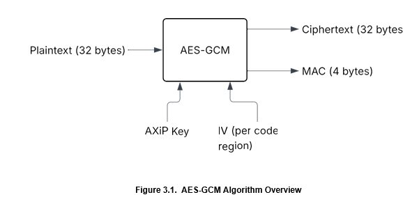
AXiP utilizes the AES-GCM encryption algorithm. AES-GCM is a widely adopted authenticated encryption mode that combines the confidentiality of AES-CTR with the integrity assurance of a Message Authentication Code (MAC).
The AES-GCM algorithm takes in 32-bytes of plaintext and encrypts it with the AXiP Key stored within the SE using an IV generated by the SE for each AXiP enabled code region. The output of this computation is 32-bytes of ciphertext appended with a 4-byte MAC. This 4-byte MAC is independently verifiable per 32-byte blocks of ciphertext. The MAC stored is not directly accessible by the host core, because it has no associated logical address. More details on the differences between physical and logical addresses are covered in Configuring Code Regions.
On decryption, the MAC is verified per 32-bytes of data before decrypting and executing instructions. If the ciphertext is modified at any time, the MAC will no longer be valid, which will cause the MAC verification to fail. If MAC verification fails, a hard fault will occur. This helps to ensure strong integrity, but introduces an additional memory consumption, which should be considered when planning memory usage.
AXiP Key#
The AXiP feature utilizes a single 256-bit AES key that is derived at boot from a device-unique Physical Unclonable Function (PUF) seed. The PUF is only available while the device is powered on, and the AXiP key derived from this unique seed when needed. This ensures that the AXiP key has enhanced resistance to physical attacks. As this key is derived from the PUF, it is permanent for the lifetime of the device. The AXiP key is shared across all AXiP-configured code regions of the device.
IV Generation#
Unique initialization vectors ensure that multiple encryptions of identical plaintexts yield different ciphertexts. In AXiP, IVs are generated using the True Random Number Generator (TRNG) and are stored within the SE's MTP. In order to prevent IV reuse, which could introduce predictable bit patterns, a new IV is generated when flashing a code region with AXiP enabled. For more details, see Considerations for Development Devices.
AXiP Default Device Configuration#
Series 3 devices with in-package flash are delivered secured by default, with AXiP enabled out of the box on two code regions. No additional configuration is required to use AXiP on a factory-new in-package flash devices, users only need to flash a firmware image to the predefined code region to implement AXiP.
Unlike in-package flash devices, external flash devices require external flash initialization and SE firmware programming before AXiP is enabled. After the external flash is set up, two regions are configured for AXiP, similar to the default configuration of in-package flash devices. Beyond these external flash initialization steps, region configuration and usage are equivalent to in-package devices.
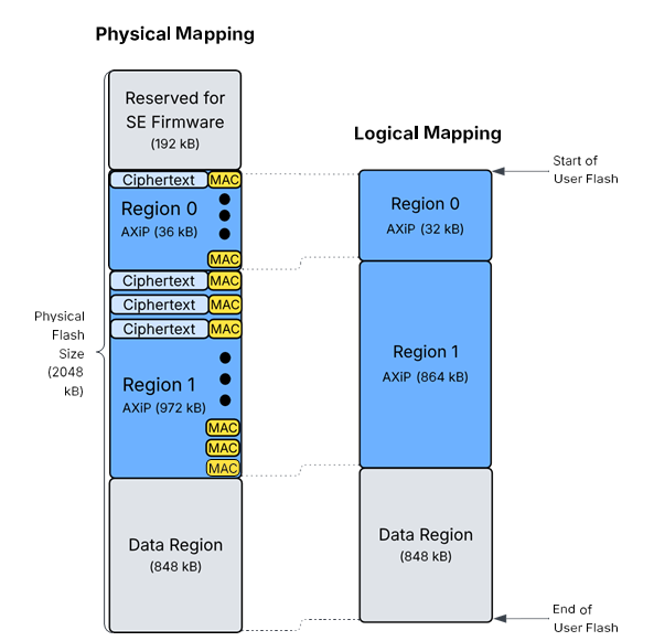
Typically, a factory-new in-package flash device is set up with Code Region 0 designated for bootloader use. This region is configured with AXiP enabled and a fixed size of 32 kB in logical address space. Code Region 1 is generally intended for application code. It is also AXiP-enabled and sized in multiples of 32 kB logical space, depending on application requirements. The data region is located after the final configured code region, and is a variable size dependent on code region configuration. The default code region sizes may vary among Series 3 OPNs, depending on the flash capacity of the in-package flash devices.
An example of default device configuration is shown below on a 2048 kB flash SixG301 device. Additional details on physical and logical flash mapping on devices with AXiP enabled can be found in Physical versus Logical Mapping.
Note: By default, the initial 192 kB of flash memory is allocated for SE Firmware. This region is reserved and not accessible to the user.