Configuring Code Regions#
Devices with in-package flash are delivered secure by default, with AXiP enabled on two code regions, so no additional configuration is typically required. However, users working with external flash devices, or those with specific application needs, may choose to configure code regions for greater flexibility. Configuring code regions is highly application dependent, so some consideration and planning is needed. This section will serve as a guide to helping users understand how to plan out code region configurations.
There are two methods that can be used in order to set a custom code region configuration. One method is to use SE Manager APIs, such as sl_se_code_region_get_config, sl_se_code_region_apply_config, and sl_se_code_region_close, which respectively read, apply, and close the custom region configuration. More details on these APIs can be found in our SE Manager Documentation.
The second method is configuring code regions through the DCI on the device using Simplicity Commander. This is the main method used in upcoming sections of this document.
Data Regions versus Code Regions#
Series 3 devices introduce the concept of separate code regions and data regions in flash. Code regions are made up of 32 kB erasable pages which are used to store firmware images. Each code region supports only one updatable firmware image, which is why it is standard practice to allocate one region for the bootloader and another for the application firmware. Alternatively, they can be combined within a single region, in which case both must be updated simultaneously and share the same version number.
Data regions are 4 kB erasable pages which are used to store data, and are most commonly used for NVM3 and GBLv4 storage. The XiP features (AXiP and EXiP) are only applicable to code regions, not to data regions. This does not mean that data in the data region cannot be protected; NVM3 and GBLv4 data can be encrypted before it is written to the data region.
It is important to take into account the size of the data region required by an application when configuring code regions, as resizing code regions impacts the size of the data region. Configuring code regions via OTA updates is not supported. Thus, users should ensure enough space is reserved for the bootloader, application firmware, NVM3, GBLv4, and any other required components, for the lifetime of the device.
Physical versus Logical Mapping#
Differences in physical and logical flash mapping must be considered when resizing regions to ensure no code or data regions are overwritten. Physical flash space is allocated to regions based on configuration (AXiP, EXiP, plaintext) and region type (code, data, or reserved for SE firmware).
One reserved region in physical flash is the 192 kB area allocated for SE Firmware. It is placed at the beginning of physical flash and ends at the start of user-accessible flash, or the start of code region 0.
When AXiP is enabled, an extra 4-bytes of MAC data is stored for every 32-bytes of ciphertext. Thus, this results in 4 kB of MAC data stored for every 32 kB ciphertext data. This MAC is not directly accessible, because it has no associated logical address, but must be accounted for when calculating code and data region sizes.
For EXiP, plaintext code regions, and data regions, one-to-one mapping is used between physical and logical flash maps, independent of other code regions. Address translation between physical and logical flash mapping is handled by the EXTMEM subsystem.
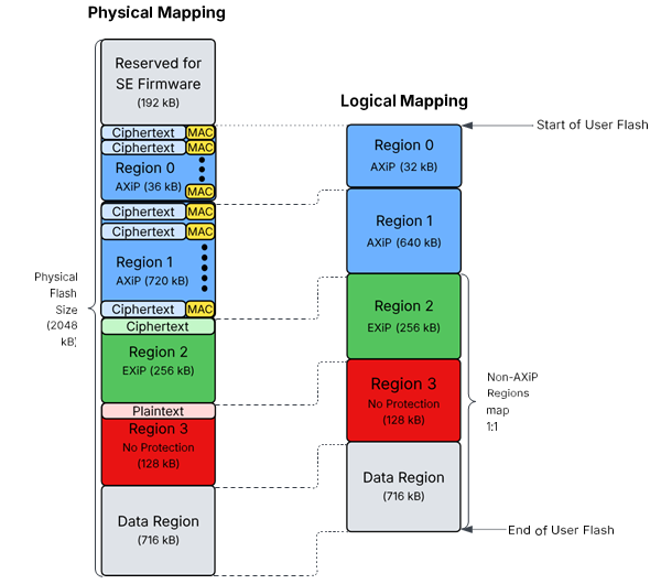
An example of a SixG301 device with a custom code region configuration is shown above. The image illustrates a side-by-side comparison of physical and logical address space. In this example, AXiP is enabled on Region 0 and 1, resulting in 4 kB of MAC data stored per 32 kB of ciphertext. The EXiP, plaintext, and data regions map one to one.
To determine the remaining flash available for the data region, subtract the total size of all configured code regions (including MAC overhead) and the reserved SE firmware area from the total flash size. The result is the available space for the data region. For example:
Data Region Size = (Total Flash) - (Reserved SE Firmware Region) - (Total Code Region Size, including MAC overhead)
Code Region Configuration File#
To configure code regions via the DCI, Commander takes in a YAML format configuration file, which can be generated by reading the current configuration from the device. The examples section of this document contains step-by-step instructions on how to use this file to reconfigure code regions. An example code region configuration file in YAML format is shown below.
regions:
- size_kb: 32
protection: encrypted_authenticated
- size_kb: 1408
protection: encrypted_authenticatedListed below are the required fields for the configuration file as well as their acceptable values.
Regions#
Up to 8 regions can be configured
Each region is listed as a bullet point, starting from Region 0 at the top of the file, and incrementing one region at a time.
Each region must have a size and protection type set.
Size#
Each region must be sized as a multiple of 32 kB.
Protection Type#
Setting the protection to
encrypted_authenticatedenables AXiP on the code region.Setting the protection to
encryptedenables EXiP on the code region.Setting the protection to
nonedisables all protection on the code region, resulting in the code stored in plaintext.
For example, the code region configuration for the custom configuration illustrated in Figure 5.1 is listed below.
regions:
- size_kb: 32
protection: encrypted_authenticated
- size_kb: 640
protection: encrypted_authenticated
- size_kb: 256
protection: encrypted
- size_kb: 128
protection: noneNote: When code regions are modified, firmware images must also be updated to ensure the linker files align with the code region configuration. Refer to Platform Software Documentation for details on modifying linker files to match code region configurations.
Closing a Code Region#
Once code regions are configured and firmware is programmed to the device, code regions must be closed. Closing a code region locks the code region to prevent writes to the region, as well as further region configuration. Each time a code region is closed, the SE's MTP is updated, which causes an SE OTP bit to be used. More details on SE OTP bits are covered in the following section.
Note: To open a closed code region, an erase of the region must be performed.