Network Core Configuration#
Micrium OS Network core includes the TCP/IP stack and the service modules DHCP and DNS. Before using these components, you must properly configure the network core. There are two groups of configuration parameters for the network core:
Furthermore, to successfully configure a network interface, there are two additional configuration layers:
Network Core Compile-Time Configurations#
To configure the Micrium OS Network core module, you make use of approximately 50 #defines located in your application’s net_cfg.h file. The core module uses #defines because they allow code and data sizes to be scaled based on the features you choose to enable and the number of network objects you configure. This allows the ROM and RAM footprints of the Network module to be adjusted based on your application's requirements.
Most of the #defines should be configured with the default configuration values. A handful of these values will likely never be changeable because there is currently only one configuration choice available. This leaves approximately a dozen #defines that you might need to configure.
We recommend that you begin the configuration process with the default values, which are shown in bold.
The topics in this section are organized following the order in the template configuration file, net_cfg.h
Mandatory Configurations#
Debug Features Configuration#
Table - Debug Feature Constants#
Constant | Description | Possible Values |
|---|---|---|
NET_DBG_CFG_MEM_CLR_EN | Clears the internal network data structures when allocated or de-allocated. By clearing, all bytes in internal data structures are set to ‘0’ or to their default initialization values. This configuration is typically set to DEF_DISABLED unless you need to examine the contents of the internal network data structures for debugging purposes. Having the internal network data structures cleared generally helps to differentiate between “proper” data and “pollution”. Note that the network performance can be affected when enabled. | DEF_ENABLED or DEF_DISABLED |
Counters Configuration#
The Network core module contains code that increments counters to keep track of statistics such as the number of packets received, the number of packets transmitted, etc. It also contains counters that are incremented when error conditions are detected.
Table - Counter Configuration Constants#
Constant | Description | Possible Values |
|---|---|---|
NET_CTR_CFG_STAT_EN | Allocates code and data space used to keep track of statistics. | DEF_ENABLED or DEF_DISABLED |
NET_CTR_CFG_ERR_EN | Allocates code and data space used to keep track of errors. | DEF_ENABLED or DEF_DISABLED |
Statistic Pool Configuration#
The Network core module uses pools to allocate many of its internal objects. Using the macro configurations below, the statistics can be enabled for each of those pools individually.
Table - Statistic Pool Configuration Constants#
Constant | Description | Possible Values |
|---|---|---|
NET_STAT_POOL_BUF_EN | Allocates code and data space for the Buffers statistic pool. | DEF_ENABLED or DEF_DISABLED |
NET_STAT_POOL_ARP_EN | Allocates code and data space for the ARP cache statistic pool. | DEF_ENABLED or DEF_DISABLED |
NET_STAT_POOL_NDP_EN | Allocates code and data space for the NDP cache statistic pool. | DEF_ENABLED or DEF_DISABLED |
NET_STAT_POOL_IGMP_EN | Allocates code and data space for the IGMP host group statistic pool. | DEF_ENABLED or DEF_DISABLED |
NET_STAT_POOL_MLDP_EN | Allocates code and data space for the MLDP host group statistic pool. | DEF_ENABLED or DEF_DISABLED |
NET_STAT_POOL_TMR_EN | Allocates code and data space for the Network Timer statistic pool. | DEF_ENABLED or DEF_DISABLED |
NET_STAT_POOL_SOCK_EN | Allocates code and data space for the Socket statistic pool. | DEF_ENABLED or DEF_DISABLED |
NET_STAT_POOL_CONN_EN | Allocates code and data space for the Connection statistic pool. | DEF_ENABLED or DEF_DISABLED |
NET_STAT_POOL_TCP_CONN_EN | Allocates code and data space for the TCP Connection statistic pool. | DEF_ENABLED or DEF_DISABLED |
Network Interfaces Configuration#
Table - Interface Configuration Constants#
Constant | Description | Possible Values |
|---|---|---|
NET_IF_CFG_MAX_NBR_IF | Specifies the maximum number of network interfaces that the network module can create. | 1 u if a single network interface is present. |
NET_IF_CFG_LOOPBACK_EN | Allocates code and data space used to support the loopback interface for internal-only communication. | DEF_ENABLED or DEF_DISABLED |
NET_IF_CFG_TX_SUSPEND_TIMEOUT_MS | Specifies the network interface transmit suspend timeout value in milliseconds. | 1 u |
NET_IF_CFG_WAIT_SETUP_READY_EN | Specifies whether the wait feature for the interface setup is enabled. When enabled, your application can wait for the network interface setup to complete by using the function NetIF_WaitSetupReady() . The network interface setup consists mainly of IP address configurations. The NetIF_WaitSetupReady() function will wait for all configuration processes that were specified in the start function to complete before returning. | DEF_ENABLED or DEF_DISABLED |
Address Resolution Protocol (ARP) Configuration#
Table - ARP Configuration Constants#
Constant | Description | Possible Values |
|---|---|---|
NET_ARP_CFG_CACHE_NBR | Specifies the number of ARP cache entries. | 3 u |
ARP caches the mapping of IPv4 addresses to physical (i.e., MAC) addresses. NET_ARP_CFG_NBR_CACHE specifies the number of ARP cache entries. Each cache entry requires approximately 18 bytes of RAM, plus seven pointers, plus a hardware address and protocol address (10 bytes assuming Ethernet interfaces and IPv4 addresses).
The number of ARP caches required by your application depends on how many different hosts your application is expected to communicate with. If your application communicates only with hosts on remote networks via the local network’s default gateway (i.e., router), then you need to configure only a single ARP cache.
To test the network module with a small network, the default number of three ARP caches should be sufficient.
Neighbor Discovery Protocol (NDP) Configuration#
Table - NDP Configuration Constants#
Constant | Description | Possible Values |
|---|---|---|
NET_NDP_CFG_CACHE_NBR | Configures the number of NDP Neighbor cache entries. | 6 u |
NET_NDP_CFG_DEST_NBR | Configures the number of NDP Destination cache entries. | 5 u |
NET_NDP_CFG_PREFIX_NBR | Configures the number of NDP Prefix entries. | 5 u |
NET_NDP_CFG_ROUTER_NBR | Configures the number of NDP Router entries. | 1 u |
NDP caches the mapping of IPv6 addresses to physical (i.e., MAC) addresses. NET_NDP_CFG_NBR_CACHE specifies the number of NDP Neighbor cache entries. Each cache entry requires approximately 18 bytes of RAM, plus seven pointers, plus a hardware address and protocol address (22 bytes assuming Ethernet interfaces and IPv6 addresses).
NDP also caches recent IPv6 destination addresses by mapping next-hop address to the final destination address, thereby relieving the network stack from having to re-calculate the next-hop for each packet to send. NET_NDP_CFG_DEST_NBR specifies the number of NDP destination caches available for the TCP/IP stack.
In IPv6, routers send router advertisement messages to inform hosts about different values such as the on-link IPv6 prefix. Those on-link prefixes are stored in an NDP prefix list. NET_NDP_CFG_PREFIX_NBR specifies the number of prefix entries available in the list.
IPv6 defines an algorithm to chose the optimal router on the network to use to transmit packets in case more than one IPv6 router is available. NET_NDP_CFG_ROUTER_NBR specifies the number of router entries that can be stored by the TCP/IP stack.
IPv4 Layer Configuration#
Table - IPv4 Configuration Constants#
Constant | Description | Possible Values |
|---|---|---|
NET_IPv4_CFG_EN | Enables the IPv4 module. | DEF_ENABLED or DEF_DISABLED |
NET_IPv4_CFG_LINK_LOCAL_EN | Enables the IPv4 Link-Local address module. | DEF_ENABLED or DEF_DISABLED |
NET_IPv4_CFG_IF_MAX_NBR_ADDR | Specifies the maximum number of IPv4 addresses that may be configured for all network interfaces at run-time. | At least 1 |
IPv6 Layer Configuration#
Constant | Description | Possible Values |
|---|---|---|
NET_IPv6_CFG_EN | Enables the IPv6 module. | DEF_ENABLED or DEF_DISABLED |
NET_IPv6_CFG_ADDR_AUTO_CFG_EN | Enables the IPv6 Stateless Address Auto-Configuration module. | DEF_ENABLED or DEF_DISABLED |
NET_IPv6_CFG_DAD_EN | Enables the Duplication Address Detection (DAD) module. | DEF_ENABLED or DEF_DISABLED |
NET_IPv6_CFG_IF_MAX_NBR_ADDR | Specifies the maximum number of IPv6 addresses that may be configured for all network interfaces at run-time. | At least 2 |
Table - IPv6 Configuration Constants#
Multicast Configuration (IGMP and MLDP)#
Table - Multicast Configuration Constants#
Constant | Description | Possible Values |
|---|---|---|
NET_MCAST_CFG_IPv4_RX_EN | Enables multicast support in reception for IPv4. | DEF_ENABLED or DEF_DISABLED |
NET_MCAST_CFG_IPv4_TX_EN | Enables multicast support in transmission for IPv4. | DEF_ENABLED or DEF_DISABLED |
NET_MCAST_CFG_HOST_GRP_NBR_MAX | Specifies the maximum number of IGMP and MLDP host groups that may be joined at any time. | 4 u |
NET_MCAST_CFG_MAX_NBR_HOST_GRP configures the maximum number of IGMP and MLDP host groups that may be joined at any time. Each group entry requires approximately 12 bytes of RAM, plus three pointers, plus a protocol address (4 bytes assuming IPv4 address).
The number of host groups required by your application depends on how many host groups you expect your application to join at a given time. Since each configured multicast address requires its own host group, we recommend that you configure at least one host group per multicast address used by the application, plus one additional host group. Thus for a single multicast address, we recommend that you set NET_MCAST_CFG_MAX_NBR_HOST_GRP to an initial value of 2.
If IPv6 is enabled, MLDP multicast is enabled automatically and NET_MCAST_CFG_MAX_NBR_HOST_GRP must be adjusted because an interface with IPv6 support will need at least two multicast address.
Socket Layer Configuration#
The Network module supports BSD 4.x sockets and basic socket API for the TCP/UDP/IP protocols.
Table - Socket Configuration Constants#
Constant | Description | Possible Values |
|---|---|---|
NET_SOCK_CFG_SOCK_NBR_TCP | Specifies the total number of TCP connections. | 5 |
NET_SOCK_CFG_SOCK_NBR_UDP | Specifies the total number of UDP connections. | 2 |
NET_SOCK_CFG_SEL_EN | Enables socket select functionality. | DEF_ENABLED or DEF_DISABLED |
NET_SOCK_CFG_CONN_ACCEPT_Q_SIZE_MAX | Specifies the maximum size of the stream-type sockets' accept queue. | 2 |
NET_SOCK_CFG_RX_Q_SIZE_OCTET | Specifies the buffer size of the socket receive queue. | 4096 |
NET_SOCK_CFG_TX_Q_SIZE_OCTET | Specifies the buffer size of the socket transmit queue. | 4096 |
TCP Layer Configuration#
Table - TCP Configuration Constants#
Constant | Description | Possible Values |
|---|---|---|
NET_TCP_CFG_EN | Enables the TCP module. | DEF_ENABLED or DEF_DISABLED |
UDP Layer Configuration#
Table - UDP Configuration Constants#
Constant | Description | Possible Values |
|---|---|---|
NET_UDP_CFG_RX_CHK_SUM_DISCARD_EN | Used to determine whether received UDP packets without a valid checksum are discarded or are handled and processed. Before a UDP datagram checksum is validated, it is necessary to check whether the UDP datagram was transmitted with or without a computed checksum. | DEF_ENABLED or DEF_DISABLED |
NET_UDP_CFG_TX_CHK_SUM_EN | Used to determine whether UDP checksums are computed for transmission to other hosts. | DEF_ENABLED or DEF_DISABLED |
Transport Layer Security Configuration#
Table - Security Management Constants#
Constant | Description | Possible Values |
|---|---|---|
NET_SECURE_CFG_MAX_NBR_SOCK_SERVER | Specifies the total number of server secure sockets. | 5 |
NET_SECURE_CFG_MAX_NBR_SOCK_CLIENT | Specifies the total number of client secure sockets. | 5 |
NET_SECURE_CFG_MAX_CERT_LEN | Specifies the maximum length (in octets) of server certificates. | 2048 |
NET_SECURE_CFG_MAX_KEY_LEN | Specifies the maximum length (in octets) of server keys. | 2048 |
NET_SECURE_CFG_MAX_NBR_CA | Specifies the maximum number of certificate authorities that can be installed. | 1 |
NET_SECURE_CFG_MAX_CA_CERT_LEN | Specifies the maximum length (in octets) of certificate authority certificates. | 2048 |
Core Modules Configuration#
The network core module includes basic network services such as DHCP and DNS client, which can be disabled if not required.
Table - Core Modules Configuration#
Constant | Description | Possible Values |
|---|---|---|
NET_DHCP_CLIENT_CFG_MODULE_EN | Enables the DHCP client module. | DEF_ENABLED or DEF_DISABLED |
NET_DNS_CLIENT_CFG_MODULE_EN | Enables the DNS client module. | DEF_ENABLED or DEF_DISABLED |
Advanced Configurations#
The Network module has many compile-time configurations that are already defined by the module with default values. Those values should work for most cases, but your application can still override them if necessary.
Table - Network Core Default Configuration#
{@Manual intervention complex table}
Name | Description | Default Value |
|---|---|---|
NET_TMR_CFG_NBR_TMR | By default, the network timer pool size has no limits.To limit the maximum number of network timers, you can adjust this configuration. | LIB_MEM_BLK_QTY_UNLIMITED |
Socket | ||
NET_SOCK_DFLT_BSD_EN | Enable or Disable BSD API and data type declaration. By default, the API and declaration are included.Note that your application doesn't require BSD API and you experimenting issue with duplication declaration with your compiler you can disable the BSD compatibility. If you BSD compatibility is required and you experimenting duplication declaration you have to change your toolchain setting to remove the BSD and POSIX declaration. | DEF_ENABLED |
NET_SOCK_DFLT_NO_BLOCK_EN | Sets all sockets as non-blocking. By default, sockets are set to block.Note that it's possible to change the socket's blocking mode at run-time using the Socket Option API. | DEF_DISABLED |
NET_SOCK_DFLT_PORT_NBR_RANDOM_BASE | Specifies the initial random port number. By default, the random port number start at 49152. | 49152 |
NET_SOCK_DFLT_TIMEOUT_RX_Q_MS | Specifies the timeout for the socket reception queue in milliseconds.When a socket is set as blocking, the specified timeout value is used.Timeout values may also be configured to never time out with the network time constant NET_TMR_TIME_INFINITE.Note that it's possible to change at run-time any timeout values using the Socket Option API. | 10000 |
NET_SOCK_DFLT_TIMEOUT_CONN_REQ_MS | Specifies the default timeout for the socket connection connect request in milliseconds.When a socket is set as blocking the specified timeout value is used.Timeout values may also be configured to never time out with the network time constant NET_TMR_TIME_INFINITE.Note that it's possible to change at run-time any timeout values using the Socket Option API. | 10000 |
NET_SOCK_DFLT_TIMEOUT_CONN_ACCEPT_MS | Specifies the timeout for the socket connection accept in milliseconds.When a socket is set as blocking the following specified timeout value is used.Timeout values may also be configured to never time out with the network time constant NET_TMR_TIME_INFINITE.Note that it's possible to change at run-time any timeout values using the Socket Option API. | 10000 |
NET_SOCK_DFLT_TIMEOUT_CONN_CLOSE_MS | Specifies the timeout for the socket connection close in milliseconds.When a socket is set as blocking the following specified timeout value is used.Timeout values may also be configured to never time out with the network time constant NET_TMR_TIME_INFINITE.Note that it's possible to change at run-time any timeout values using Socket Option API. | 10000 |
TCP | ||
NET_TCP_DFLT_RX_WIN_SIZE_OCTET | Specifies the TCP RX window size.By default, the TCP RX window is set to equal the socket RX queue size. TCP windows must be properly configured to optimize performance (see section Configuring Window Sizes ).Note that it's possible to decrease window size at run time using Socket Option API. | NET_SOCK_CFG_RX_Q_SIZE_OCTET |
NET_TCP_DFLT_TX_WIN_SIZE_OCTET | Specifies the TCP TX window size.By default, the TCP TX window is set to equal the socket TX queue size. TCP windows must be properly configured to optimize performance (see section Configuring Window Sizes ).Note that it's possible to decrease window size at run time using Socket Option API. | NET_SOCK_CFG_TX_Q_SIZE_OCTET |
NET_TCP_DFLT_TIMEOUT_CONN_MAX_SEG_SEC | Specifies the TIME_WAIT connection timeout.As shown in the TCP state diagram (see RFC #793), before moving to the 'CLOSED' state, the connection waits for a short period (typically 2 minutes), which is called the TIME_WAIT state. This timeout prevents the TCP connection from becoming immediately available for subsequent TCP connections. But this delay can be a problem for embedded systems that cannot handle many simultaneous connections, especially when many TCP connections are made in a small period of time. Therefore this timeout is set to 0 by default to avoid this kind of problem, and the connection is made available as soon as the TIME_WAIT state is reached.Note that it is possible to change the MSL timeout for a specific TCP connection using Socket Option API. | 0 |
NET_TCP_DFLT_TIMEOUT_CONN_FIN_WAIT_2_SEC | Specifies the FIN_WAIT_2 connection timeout.In the FIN_WAIT_2 state, the local endpoint is waiting for a connection termination request from the remote endpoint. To prevent a connection from being left open indefinitely if the termination request never arrives, the TCP connection's timer is set to 15 seconds by default, and when it expires the connection is dropped. | 15 |
NET_TCP_CFG_NBR_CONN | Specifies the total number of TCP connections.The number of TCP connections is based on the number of TCP sockets and the accept queue size when TIME_WAIT is set to 0 ms. However, since the default TIME_WAIT value can be modified, you might need to increase the number of TCP connections in order to establish new connections when waiting for the TIME_WAIT expiration. | 0 |
NET_TCP_DFLT_TIMEOUT_CONN_ACK_DLY_MS | Specifies the ACK delay in milliseconds.By default, an ACK is generated within 500 ms of the arrival of the first unacknowledged packet, as specified in RFC #2581, Section 4.2. | 500 |
NET_TCP_DFLT_TIMEOUT_CONN_RX_Q_MS | Specifies the default timeout for the TCP Reception Queue in milliseconds.This value determines how long a socket is allowed to remain blocking when receiving.Timeout values may also be configured to never time out with the network time constant NET_TMR_TIME_INFINITE.Note that it's possible to change at run-time any timeout values using the Socket Option API. | 1000 |
NET_TCP_DFLT_TIMEOUT_CONN_TX_Q_MS | Specifies the default timeout for the TCP Transmission Queue, in milliseconds.This value determines how long a socket is allowed to remain blocking when transmitting.Timeout values may also be configured to never time out with network time constant, NET_TMR_TIME_INFINITE.Note that it's possible to change at run-time any timeout values using the Socket Option API. | 1000 |
Checksum Offload | ||
By default, all checksum are validated by the stack. However, it is possible to enable or disable validation for specific checksums. Enable any of the following defines in your net_cfg.h file to change the default behavior. Turning off checksum validation can also provide a performance boost. | ||
NET_IPV4_CFG_CHK_SUM_OFFLOAD_RX_EN | Turn off validation in reception for IPv4 checksums. | DEF_DISABLED |
NET_IPV4_CFG_CHK_SUM_OFFLOAD_TX_EN | Turn off calculation in transmission for IPv4 checksums. | DEF_DISABLED |
NET_ICMP_CFG_CHK_SUM_OFFLOAD_RX_EN | Turn off validation in reception for ICMP checksums. | DEF_DISABLED |
NET_ICMP_CFG_CHK_SUM_OFFLOAD_TX_EN | Turn off calculation in transmission for ICMP checksums. | DEF_DISABLED |
NET_UDP_CFG_CHK_SUM_OFFLOAD_RX_EN | Turn off validation in reception for UDP checksums. | DEF_DISABLED |
NET_UDP_CFG_CHK_SUM_OFFLOAD_TX_EN | Turn off calculation in transmission for UDP checksums. | DEF_DISABLED |
NET_TCP_CFG_CHK_SUM_OFFLOAD_RX_EN | Turn off validation in reception for TCP checksums. | DEF_DISABLED |
NET_TCP_CFG_CHK_SUM_OFFLOAD_TX_EN | Turn off calculation in transmission for TCP checksums. | DEF_DISABLED |
Network Core Run-Time Configurations#
This section describes the application-specific configurations of the Micrium OS Network module, that are specified at run-time.
For more information on how default run-time configuration values can be changed or used, see Initialization of the Common Module .
For more information on how to initialize any Micrium OS modules, see Stacks Initialization Methods .
Network Core Configuration#
To initialize the Micrium OS Network Core module, you must call the function Net_Init(). This function does not have any mandatory configuration argument.
Optional Configurations#
The configurations described below are optional; if you do not set them in your application, the default values will apply. The default values can be retrieved via the structure Net_InitCfgDflt.
There are two different ways of overriding the default values:
The first method is to via the four functions listed in the table below.
The second method is for your application to define the configuration structure over the one declared by Micrium OS (as an extern variable).
Note that in either case, these configurations must be set before calling the Net_Init() function. |
|---|
Method 1 - Specific Function Calls#
Memory Segments#
Specifies a pointer to a memory segment to use when allocating control data for the network core.
Configuration Type | Function to Call | Default | Field From Default Configuration Structure |
|---|---|---|---|
MEM_SEG* | Net_ConfigureMemSeg() | .MemSegPtr |
Network Core Task's Stack Size#
Specifies the size (in CPU_STK elements) of the stack for the network core task. The core stack is used for the main TCP/IP core operations: receive packets, demux packets up to the socket layer, network timer handling, free network buffers, etc.
Configuration Type | Function to Call | Default | Field From Default Configuration Structure |
|---|---|---|---|
CPU_STK_SIZECPU_STK* | Net_ConfigureCoreTaskStk() | A stack of 512 elements allocated on network core's memory segment. | .CoreStkSizeElements.CoreStkPtr |
Network Core Services Task's Stack Size#
Specifies the size (in CPU_STK elements) of the stack for the network core services task. The core services task is used for the DHCP client and DNS client module.
Configuration Type | Function to Call | Default | Field From Default Configuration Structure |
|---|---|---|---|
CPU_STK_SIZECPU_STK* | Net_ConfigureCoreSvcTaskStk() | A stack of 512 elements allocated on network core's memory segment. | .CoreSvcStkSizeElements.CoreSvcStkPtr |
DNS Configuration#
Specifies the configuration structure for the DNS client core module. The fields in this structure are as follows:
Field | Description | Possible Values |
|---|---|---|
.HostNameLenMax | Maximum host name length that can be requested. | Any 16-bit unsigned integer, 255 u by default. |
.CacheEntriesMaxNbr | Number of entries the cache can contain. | Any unsigned integer, LIB_MEM_BLK_QTY_UNLIMITED by default. |
.AddrIPv4MaxPerHost | The maximum number of IPv4 addresses that can be stored by a host in the cache.Only valid if IPv4 is enabled. | Any unsigned integer, LIB_MEM_BLK_QTY_UNLIMITED by default. |
.AddrIPv6MaxPerHost | The maximum number of IPv6 addresses that can be stored by a host in the cache.Only valid if IPv6 is enabled. | Any unsigned integer, LIB_MEM_BLK_QTY_UNLIMITED by default. |
.OpDly_ms | Configures the operations delay in integer milliseconds. | Any 8-bit unsigned integer, 50 u by default. |
.ReqRetryNbrMax | Configures maximum of request resolution retry. | Any 8-bit unsigned integer, 3 u by default. |
.ReqRetryTimeout_ms | Configures timeout before a request resolution retry. | Any 16-bit unsigned integer, 1000 u by default. |
.DfltServerAddrFallbackEn | Enables the DNS process to fallback to the default DNS server address if no address is available. By default, the fallback DNS server address is 8.8.8.8 | DEF_ENABLED or DEF_DISABLED |
Configuration Type | Function to Call | Default | Field From Default Configuration Structure |
|---|---|---|---|
DNSc_CFG | Net_ConfigureDNS_Client() | See structure's description. | .DNSc_Cfg |
Method 2 - Externalized Structure#
If you prefer to use the advanced configuration method, you must set the flag RTOS_CFG_EXTERNALIZE_OPTIONAL_CFG to DEF_ENABLED. In addition, the Network module will assume that your application will define a NET_INIT_CFG structure named Net_InitCfg. Optionally, you may assign Net_InitCfg the value of NET_INIT_CFG_DFLT to begin, and then modify some fields (see the table from Method 1) to suit your application's needs. See Initializing the Network Core Module for more information.
Post-Init Configurations#
This section describes the configurations that can be set at any time during execution after you call the function Net_Init().
These configurations are optional. If you do not set them in your application, the default configurations will apply.
Configurations | Description | Type | Function to call | Default |
|---|---|---|---|---|
Network core task priority | Net_Init() creates a task for handling the TCP/IP core. You can change the priority of this task at any time. | RTOS_TASK_PRIO | Net_CoreTaskPrioSet() | |
Network core services task priority | Net_Init() creates a task for handling core services such as the DHCP client and the DNS client. You can change the priority of this task at any time. | RTOS_TASK_PRIO | Net_CoreSvcTaskPrioSet() |
Network Interface Controller Configuration#
The approach to configuring your network interface controller is a bit different depending on the interface type. The sections below discuss the different strategies for the two supported network interfaces: Ethernet and Wi-Fi.
Ethernet Controller#
For an Ethernet interface controller, all the application and hardware parameters are grouped into one global configuration structure named NET_DEV_CFG_ETHER. Each Ethernet interface present on your board must have its own NET_DEV_CFG_ETHER object. This object must also be defined in the BSP files of your project because it will be passed as an argument when registering the network interface with the BSP_OS_Init() function. Refer to the section Network Core Hardware Porting Guide for more details.
The NET_DEV_CFG_ETHER object is passed to the network stack during the registration process inside the BSP. So, when your application adds an Ethernet interface (using the NetIF_Ether_Add() function), there is no need to pass arguments describing the interface configuration.
Table - NET_DEV_CFG_ETHER Configuration Structure in the Network Interface Controller Configuration page describes each field available in this configuration structure.
Table - NET_DEV_CFG_ETHER Configuration Structure#
Field | Description |
|---|---|
.RxBufPoolType | Specifies the memory location for the receive data buffers. Buffers may be located either in main memory or in a dedicated memory region. This setting is used by the Interface layer to initialize the Rx memory pool. This field must be set to one of two macros: NET_IF_MEM_TYPE_MAIN or NET_IF_MEM_TYPE_DEDICATED. You may want to set this field when using DMA with dedicated memory. It is possible that you might have to store descriptors within the dedicated memory if your device requires it. |
.RxBufLargeSize | Specifies the size of all receive buffers. Specifying a value is required. The default buffer length is set to 1518 bytes, which corresponds to the Maximum Transmission Unit (MTU) size for an Ethernet network. For DMA-based Ethernet controllers, you must set the receive data buffer size to be greater or equal to the size of the largest receivable frame. If the size of the total buffer allocation is greater than the amount of available memory in the chosen memory region, a run-time error will be generated when the device is initialized. |
.RxBufLargeNbr | Specifies the number of receive buffers that will be allocated to the device. There should be at least one receive buffer allocated, and it is recommended to have at least ten receive buffers. The optimal number of receive buffers depends on your application. |
.RxBufAlignOctets | Specifies the required alignment of the receive buffers, in bytes. Some devices require that the receive buffers be aligned to a specific byte boundary. Additionally, some processor architectures do not allow multi-byte reads and writes across word boundaries and therefore may require buffer alignment. In general, it is probably a best practice to align buffers to the data bus width of the processor, which may improve performance. For example, a 32-bit processor may benefit from having buffers aligned on a four-byte boundary. |
.RxBufIxOffset | Specifies the receive buffer offset in bytes. Most devices receive packets starting at base index zero in the network buffer data areas. However, some devices may buffer additional bytes prior to the actual received Ethernet packet. This setting configures an offset to ignore these additional bytes. If a device does not buffer any additional bytes ahead of the received Ethernet packet, then an offset of 0 must be specified. However, if a device does buffer additional bytes ahead of the received Ethernet packet, then you should configure this offset with the number of additional bytes. |
.TxBufPoolType | Specifies the memory placement of the transmit data buffers. Buffers may be placed either in main memory or in a dedicated memory region. This field is used by the Interface layer, and it should be set to one of two macros: NET_IF_MEM_TYPE_MAIN or NET_IF_MEM_TYPE_DEDICATED. When DMA descriptors are used, they may be stored in dedicated memory. |
.TxBufLargeSize | Specifies the size of the large transmit buffers in bytes. This field has no effect if the number of large transmit buffers is configured to zero. Setting the size of the large transmit buffers below 1594 bytes may hinder the TCP/IP module’s ability to transmit full sized IP datagrams since IP transmit fragmentation is not yet supported. We recommend setting this field between 1594 and 1614 bytes in order to accommodate all of the maximum transmit packet sizes for TCP-IP’s protocols.You can also optimize the transmit buffer if you know in advance what the maximum size of the packets the user will want to transmit through the device are. |
.TxBufLargeNbr | Specifies the number of large transmit buffers allocated to the device. You may set this field to zero to make room for additional small transmit buffers, however, the size of the maximum transmittable packet will then depend on the size of the small transmit buffers. |
.TxBufSmallSize | Specifies the small transmit buffer size. For devices with a minimal amount of RAM, it is possible to allocate small transmit buffers as well as large transmit buffers. In general, we recommend a small transmit buffer size of 64 bytes, however, you may adjust this value according to the application requirements. This field has no effect if the number of small transmit buffers is configured to zero. |
.TxBufSmallNbr | Specifies the numbers of small transmit buffers. This field controls the number of small transmit buffers allocated to the device. You may set this field to zero to make room for additional large transmit buffers if required. |
.TxBufAlignOctets | Specifies the transmit buffer alignment in bytes. Some devices require that the transmit buffers be aligned to a specific byte boundary. Additionally, some processor architectures do not allow multi-byte reads and writes across word boundaries, and therefore may require buffer alignment. In general, it's probably a best practice to align buffers to the data bus width of the processor which may improve performance. For example, a 32-bit processor may benefit from having buffers aligned on a four-byte boundary. |
.TxBufIxOffset | Specifies the transmit buffer offset in bytes. Most devices only need to transmit the actual Ethernet packets as prepared by the higher network layers. However, some devices may need to transmit additional bytes prior to the actual Ethernet packet. This setting configures an offset to prepare space for these additional bytes. If a device does not transmit any additional bytes ahead of the Ethernet packet, the default offset of zero should be configured. However, if a device does transmit additional bytes ahead of the Ethernet packet then configure this offset with the number of additional bytes. |
.MemAddr | Specifies the starting address of the dedicated memory region for devices with this memory type. For devices with non-dedicated memory, you can initialize this field to zero. You may use this setting to put DMA descriptors into the dedicated memory. |
.MemSize | Specifies the size of the dedicated memory region in bytes for devices with this memory type. For devices with non-dedicated memory, you can initialize this field to zero. You may use this setting to put DMA descriptors into the dedicated memory. |
.Flags | Specify the optional configuration flags. Configure (optional) device features by logically OR’ing bit-field flags:NET_DEV_CFG_FLAG_NONE — No device configuration flags selected.NET_DEV_CFG_FLAG_SWAP_OCTETS — Swap data bytes (i.e., swap data words’ high-order bytes with data words’ low-order bytes, and vice-versa) if required by device-to-CPU data bus wiring and/or CPU endian word order. |
.RxDescNbr | Specifies the number of receive descriptors. For DMA-based devices, this value is used by the device driver during initialization in order to allocate a fixed-size pool of receive descriptors to be used by the device. The number of descriptors must be less than the number of configured receive buffers. We recommend setting this value to something within 40% and 70% of the number of receive buffers. Non-DMA based devices may configure this value to zero. You must use this setting with DMA based devices and at least two descriptors must be set. |
.TxDescNbr | Specifies the number of transmit descriptors. For DMA based devices, this value is used by the device driver during initialization to allocate a fixed size pool of transmit descriptors to be used by the device. For best performance, it’s recommended to set the number of transmit descriptors equal to the number of small, plus the number of large transmit buffers configured for the device. Non-DMA based devices may configure this value to zero. You must use this setting with DMA based devices and set at least two descriptors. |
.BaseAddr | Specifies the base address of the device’s hardware/registers. |
.DataBusSizeNbrBits | Specifies the size of device's data bus (in bits), if available. |
.HW_AddrStr | Specifies the desired device hardware address; may be NULL address or string if the device hardware address is configured or set at run-time.Depending on the driver, if this value is kept NULL or invalid, most of the device driver will automatically try to load and use the hardware address located in the memory of the device. |
.CfgExtPtr | Specifies the pointer to an extension configuration structure if needed, else set to DEF_NULL. |
There is an additional configuration structure for PHY controllers: NET_PHY_CFG_ETHER. You might need to adjust some of the configuration fields in this structure depending on your specific needs (for example, the link speed). See PHY Configuration and Information for more details.
Wi-Fi Controller#
In contrast to the Ethernet interface, the Wi-Fi interface separates the application-specific configuration parameters from the hardware parameters for the controller. So, when adding a Wi-Fi interface with NetIF_WiFi_Add(), you must pass a NET_IF_BUF_CFG argument. The NET_IF_BUF_CFG structure contains all the fields related to the network buffer configuration of a Wi-Fi interface.
Table - NET_IF_BUF_CFG Configuration Structure#
Filed | Description |
|---|---|
.RxBufLargeNbr | Specifies the number of receive buffers that will be allocated to the device. There should be at least one receive buffer allocated, and we recommend at least ten receive buffers. The optimal number of receive buffers depends on your application. |
.TxBufLargeNbr | Specifies the number of large transmit buffers allocated to the device. You may set this field to zero to make room for additional small transmit buffers; however, the size of the maximum transmittable packet will then depend on the size of the small transmit buffers. |
.TxBufSmallNbr | Specifies the numbers of small transmit buffers. This field controls the number of small transmit buffers allocated to the device. You may set this field to zero to make room for additional large transmit buffers if required. |
.BufAlignOctets | Specifies the network buffer alignment in bytes. Some devices require that the buffers be aligned to a specific byte boundary. Additionally, some processor architectures do not allow multi-byte reads and writes across word boundaries and therefore may require buffer alignment. In general, it's probably a best practice to align buffers to the data bus width of the processor, which may improve performance. For example, a 32-bit processor may benefit from having buffers aligned on a four-byte boundary. |
.BufPoolType | Specifies the memory location for the network buffers. Buffers may be located either in main memory or in a dedicated memory region. This field must be set to one of two macros: NET_IF_MEM_TYPE_MAIN or NET_IF_MEM_TYPE_DEDICATED. |
.MemAddr | Specifies the starting address of the dedicated memory region for devices with this memory type. For devices with non-dedicated memory, you can initialize this field to zero. |
.MemSize | Specifies the size of the dedicated memory region in bytes for devices with this memory type. For devices with non-dedicated memory, you can initialize this field to zero. |
Network Interface Start Setup#
To start a network interface, you need to make only one API call. This is done by providing a configuration structure as an argument to the NetIF_Ether_Start() or NetIF_WiFi_Start() functions. Each interface type has its own configuration structure since some parameters are unique. These structures include parameters for the local IP address and DHCP setup, among others.
Using this configuration structure is optional; both NetIF_Ether_Start() and NetIF_WiFi_Start() can be called with a null pointer as an argument instead. If you start the network interface without a configuration, the interface will not be active on the network until you provide the necessary configuration information using additional API calls. This would include, for example, setting the local IP address, network mask, and gateway. See the IP Address Programming section of the Network Core Programming Guide for more details.
The following sections describe the parameters for the Network Interface Start configuration structure.
Ethernet Interface#
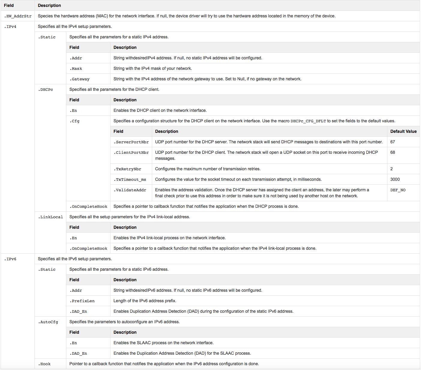
Table - NET_IF_ETHER_CFG Setup Structure in the Network Interface Start Setup page shows the setup structure for the Ethernet interface. To start and configure the Ethernet interface, call NetIF_Ether_Start() using this structure as the second argument in the function.
Table - NET_IF_ETHER_CFG Setup Structure#
Wi-Fi Interface#
Table - NET_IF_WIFI_CFG Setup Structure in the Network Interface Start Setup page shows the setup structure for the Wi-Fi interface. To start and configure the Wi-Fi interface, call NetIF_WiFi_Start() using this structure as the second argument in the function. As you can see, it is almost the same structure as for the Ethernet interface, plus additional Wi-Fi-specific parameters.
Table - NET_IF_WIFI_CFG Setup Structure#
Field | Description |
|---|---|
.HW_AddrStr | Same as for the Ethernet interface. See Table - NET_IF_ETHER_CFG Setup Structure in the Network Interface Start Setup page |
.IPv4 | Same as for the Ethernet interface. See Table - NET_IF_ETHER_CFG Setup Structure in the Network Interface Start Setup page |
.IPv6 | Same as for the Ethernet interface. See Table - NET_IF_ETHER_CFG Setup Structure in the Network Interface Start Setup page |
.Band | Configures the wireless band used by the Wi-Fi device: NET_DEV_2_4_GHZ, NET_DEV_5_0_GHZ, NET_DEV_DUAL |