File System Hardware Porting Guide#
The Micrium OS File System module includes a certain number of drivers that support a range of memory controllers.
Each memory controller used by your project requires a Board Support Package (BSP). The BSP has two purposes:
It initializes and configures any resources needed by the memory controller, but which are provided by external modules. These include the clock, GPIO, interrupts, etc.
It provides hardware information to the memory controller driver.
Micrium provides example BSPs for several popular platforms. If one is available for your platform, we recommend that you use it as a starting point. However, if no example BSP is available for your platform, the information in this section will help you understand how to create your own BSP and port the File System module to your platform.
File System Memory Driver Selection Guide#
Memory Controller Types#
The File System module supports three types of memory interfaces: NAND, NOR and SD.
Note that RAM Disk and SCSI do not have dedicated memory interfaces.
Indeed, RAM Disk emulates a volatile memory region aimed to quickly show the File System module capabilities. RAM Disk is created using the RAM of your program. The program RAM can be located in the internal (for instance SRAM) or external (for example DDR SDRAM) memory of the microcontroller. The File system does not provide any driver for such memory.
SCSI devices exist using a transport medium such as USB. The memory controller equivalent for SCSI is, in fact, a USB host controller. Consequently, supporting SCSI devices requires that you have a USB host controller on your platform.
NAND#
Microcontroller units (MCU) usually offer a few different types of peripherals to access external NAND flash devices. The peripheral depends on the NAND chip interface to the MCU: parallel or serial. For parallel NAND, the MCU can offer a dedicated NAND controller or a more flexible memory controller able to support both parallel NAND and NOR flash devices. For serial NAND, the prevailing MCU peripheral is an SPI controller.
The Micrium OS File System offers a NAND media driver that:
Supports parallel NAND. Drivers are offered for some memory controllers.
Does not support serial NAND.
NOR#
Microcontrollers usually offer a few different types of peripherals to access external NOR flash devices. The peripheral depends on the NOR chip interface to the MCU: parallel or serial. For parallel NOR, the MCU can offer a dedicated NOR controller or a more flexible memory controller able to support both parallel NAND and NOR flash devices. For serial NOR, two MCU peripherals are common, either a Quad SPI controller or an SPI controller.
The Micrium OS File System offers a NOR media driver that:
Supports parallel NOR. However, no memory controller drivers are available for the moment.
Supports serial NOR. Drivers are available for some Quad SPI controllers. SPI controller drivers are implemented by the Micrium OS IO-SPI module. Moreover, the File System offers drivers for some NOR serial flash devices (refer to the File System Drivers page to view the supported NOR).
SD#
An MCU can support SD cards using two types of peripherals: SPI or SDHC controller. An SD card can operate either in SD mode, managed by an SDHC controller, or in SPI mode, managed by an SPI controller.
The Micrium OS File System offers an SD media driver that:
Supports SD cards in SD mode. Drivers are available for some SDHC controllers.
Support SD cards in SPI mode. SPI controller drivers are implemented by the Micrium OS IO-SPI module.
File System Memory BSP Functions Guide#
A Board Support Package contains a set of functions that support your hardware platform on Micrium OS. These functions are called by the memory controller driver, and they perform hardware configuration and initialization of the clock, I/O pins, interrupts, and so on. It is your responsibility to either create these functions from scratch, or to modify example code to fit the needs and specifics of your platform.
A BSP provides a layer of abstraction between the memory controller driver and the context of the memory controller in your platform. This is useful because although the driver knows the details of a specific controller IP (such as the registers that it contains, and how to properly read and write them), the driver does not know the context in which the controller exists in your hardware solution: what are the I/O and interrupt pins, clock source, and so on. The functions of a BSP can be (and often are) customized based on how the controller is wired to your board.
Each memory controller you intend to use will need its own BSP, and each BSP defines the set of functions called by the drivers. Each of these functions is described below according to the media and memory controller type.
NOR#
Quad SPI Controller#
Initialize#
The Initialize function is called by the Quad SPI driver when a NOR media is added to the Storage layer. Listing - BSP Init Function Signature in the File System Memory BSP Functions Guide page shows the signature of this function.
Listing - BSP Init Function Signature#
CPU_BOOLEAN BSP_FS_NOR_QuadSPI_Init (FS_NOR_QUAD_SPI_ISR_HANDLE_FNCT isr_fnct,
void *p_drv_data);Its purpose is to initialize and allocate resources that will be needed by the Quad SPI controller BSP.
The initialization function receives two arguments: isr_fnct and p_drv_data, which are used when handling interrupts from the Quad SPI controller. The argument isr_fnct is a pointer to a driver function that must be called when a Quad SPI interrupt occurs, and this driver function takes p_drv_data as an argument. So it is important to save these as global variables in your BSP. If the memory controller driver does not implement interrupt-based communication, these two arguments can be ignored by using the macro PP_UNUSED_PARAM().
You must return DEF_OK from this function if it executes successfully, or DEF_FAIL, otherwise.
Clock Configuration#
The Clock Configuration function is called by the Quad SPI driver when a NOR media is added to the Storage layer. Listing - BSP Clock Configure Function Signature in the File System Memory BSP Functions Guide page shows the signature of the function.
Listing - BSP Clock Configure Function Signature#
CPU_BOOLEAN BSP_FS_NOR_QuadSPI_ClkCfg (void);Its purpose is to configure the clock of the Quad SPI controller by accessing certain registers of the microcontroller's clock management peripheral.
You must return DEF_OK from this function if it executed successfully, or DEF_FAIL, otherwise.
I/O Configuration#
The I/O Configuration function is called by the Quad SPI driver when a NOR media is added to the Storage layer. Listing - BSP IO Configure Function Signature in the File System Memory BSP Functions Guide page shows the signature of the function.
Listing - BSP IO Configure Function Signature#
CPU_BOOLEAN BSP_FS_NOR_QuadSPI_IO_Cfg (void);Its purpose is to configure the I/O pins for the Quad SPI controller.
You must return DEF_OK from this function if it executed successfully, or DEF_FAIL, otherwise.
Chip Select Enable#
The Chip Select Enable function is called by the Quad SPI driver each time communication is started with the NOR chip. Listing - BSP Chip Select Enable Function Signature in the File System Memory BSP Functions Guide page shows the signature of this function.
Listing - BSP Chip Select Enable Function Signature#
CPU_BOOLEAN BSP_FS_NOR_QuadSPI_ChipSelEn (CPU_INT16U part_slave_id);Its purpose is to select the NOR chip in order to allow communication with the NOR chip, including access to NOR registers and data memory regions. Selecting the NOR flash device is performed by driving the Chip Enable signal, and usually, an I/O peripheral register performs this job. The argument part_slave_id represents the slave ID of the NOR chip, which is used when a serial bus is shared with other external devices. If the NOR flash chip is the only device connected to the serial bus, the slave ID can be ignored.
You may not have to implement this function if the Chip Select signal is controlled directly by a Quad SPI controller's register.
You must return DEF_OK from this function if it executed successfully, or DEF_FAIL, otherwise.
Chip Select Disable#
The Chip Select Disable function is called by the Quad SPI driver to end communication with the NOR chip. Listing - Chip Select Disable Function Signature in the File System Memory BSP Functions Guide page shows the signature of this function.
Listing - Chip Select Disable Function Signature#
CPU_BOOLEAN BSP_FS_NOR_QuadSPI_ChipSelDis (CPU_INT16U part_slave_id);Its purpose is to deselect the NOR chip in order to prevent further communication with the NOR chip, including access to NOR registers and data memory regions. Selecting the NOR flash device is performed by driving the Chip Enable signal, and usually, an I/O peripheral register performs this job. The argument part_slave_id represents the slave ID of the NOR chip, which is used when a serial bus is shared with other external devices. If the NOR flash chip is the only device connected to the serial bus, the slave ID can be ignored.
You may not have to implement this function if the Chip Select signal is controlled directly by a Quad SPI controller's register.
You must return DEF_OK from this function if it executed successfully, or DEF_FAIL, otherwise.
Clock Frequency Get#
The Clock Frequency Get function is called by the driver when the controller clock is configured. Listing - BSP Clock Frequency Get Function Signature in the File System Memory BSP Functions Guide page shows the signature of this function.
Listing - BSP Clock Frequency Get Function Signature#
CPU_INT32U BSP_FS_NOR_QuadSPI_ClkFreqGet (void)It is used to determine the clock divider that must be used to achieve the desired serial clock. The function must always return the clock frequency, in Hertz, of the clock that feeds the Quad SPI controller.
ISR Handling#
The CMSIS standard function QSPIx_IRQHandler() is called each time a QSPI interrupt is triggered. This function is defined as weak in the Silicon Labs Gecko SDK. If the memory controller driver implements interrupt-based communication, this function must be redefined in the BSP to properly handle the IRQ. Otherwise, it is not required.
SPI Controller#
Writing a BSP for NOR SPI means writing a BSP that uses the SPI driver offered by the Micrium OS IO-SPI module. Refer to SPI BSP Functions Guide for more details about the BSP functions to implement.
SCSI#
USB Host Controller#
Writing a BSP for SCSI means writing a BSP that uses the USB host driver offered by the Micrium OS USB Host module. Refer to USB Host BSP Functions Guide for more details about the BSP functions to implement.
SD#
SD Host Controller (SDHC)#
The SDHC (also called SD Card) BSP has a particularity compared to the BSPs for NOR QSPI/SPI and SD SPI: the BSP is also the memory controller's driver.
Usually, the BSP is responsible for setting the clock, interrupts, and GPIO needed by the memory controller. Thus, the BSP configures the other peripherals to allow the memory controller driver to work. The BSP is not normally a driver that implements the memory controller functions. However, in the case of SD Card, the BSP is also the memory controller's driver. This particularity will be removed in a future release of Micrium OS File System in order to simplify the SD Card BSP API.
Add#
The Add function is called by the driver when the application adds an SD media. Listing - Add Function Signature in the File System Memory BSP Functions Guide page shows the signature of this function.
Listing - Add Function Signature#
void *BSP_FS_SD_Card_Add (RTOS_ERR *p_err);Its purpose is to allocate and configure any software resources needed by the controller driver.
Open#
The Open function is called by the driver when the application opens an SD block device. Listing - Open Function Signature in the File System Memory BSP Functions Guide page shows the signature of this function.
Listing - Open Function Signature#
CPU_BOOLEAN BSP_FS_SD_Card_Open (void);Its purpose is to initialize and allocate resources that will be needed by the memory controller driver.
This function, for example, can configure:
The input clocks required by the controller
Any needed GPIO pins
The interrupt (in the interrupt controller) if the controller is used in interrupt mode
Any registers required to start the controller's operations
Close#
The Close function is called by the driver when the application closes an SD block device. Listing - Close Function Signature in the File System Memory BSP Functions Guide page shows the signature of this function.
Listing - Close Function Signature#
void BSP_FS_SD_Card_Close (void);Its purpose is to terminate and free resources that were used by the memory controller driver. For instance, it may be required to disable the controller's operation and to reset some of the controller's registers to a known state.
Lock#
The Lock function is called by the driver when a sequence of SD operations must be protected. Listing - Lock Function Signature in the File System Memory BSP Functions Guide page shows the signature of this function.
Listing - Lock Function Signature#
void BSP_FS_SD_Card_Lock (void);Its purpose is to protect the SD card bus from multiple concurrent accesses. Indeed, more than one SD card can share the card bus.
Unlock#
The Unlock function is called by the driver when the sequence of SD operations to be protected is finished. Listing - Unlock Function Signature in the File System Memory BSP Functions Guide page shows the signature of this function.
Listing - Unlock Function Signature#
void BSP_FS_SD_Card_Unlock (void);Its purpose is to unlock the SD card bus.
Command Start#
The Command Start function is called by the driver when the command phase of an SD card mode transfer starts. Listing - Command Start Function Signature in the File System Memory BSP Functions Guide page shows the signature of this function.
Listing - Command Start Function Signature#
void BSP_FS_SD_Card_CmdStart (FS_DEV_SD_CARD_CMD *p_cmd,
void *p_data,
FS_DEV_SD_CARD_ERR *p_err);Its purpose is to send a command to the SD card to start an operation such as a register or a data memory access.
Command End Wait#
The Command End Wait function is called by the driver while it waits for the response of the command phase of an SD card mode transfer. Listing - Command End Wait Function Signature in the File System Memory BSP Functions Guide page shows the signature of this function.
Listing - Command End Wait Function Signature#
void BSP_FS_SD_Card_CmdEndWait (FS_DEV_SD_CARD_CMD *p_cmd,
CPU_INT32U *p_resp,
FS_DEV_SD_CARD_ERR *p_err);Its purpose is to receive a response from the SD card following the reception of a command. The response gives information about the command's execution status.
Command Data Read#
The Command Data Read function is called by the driver if the command previously sent requires a data read phase. Listing - Command Data Read Function Signature in the File System Memory BSP Functions Guide page shows the signature of this function.
Listing - Command Data Read Function Signature#
void BSP_FS_SD_Card_CmdDataRd (FS_DEV_SD_CARD_CMD *p_cmd,
void *p_dest,
FS_DEV_SD_CARD_ERR *p_err);Its purpose is to receive data from the SD card memory region. A data read phase transports only data from the memory and never register content. A register's content is retrieved as part of the command response phase.
Command Data Write#
The Command Data Write function is called by the driver if the command previously sent requires a data write phase. Listing - Command Data Write Function Signature in the File System Memory BSP Functions Guide page shows the signature of this function.
Listing - Command Data Write Function Signature#
void BSP_FS_SD_Card_CmdDataWr (FS_DEV_SD_CARD_CMD *p_cmd,
void *p_src,
FS_DEV_SD_CARD_ERR *p_err);Its purpose is to send data to the SD card memory region. A data write phase transports only data aimed to be stored in the memory and will never carry register content. A register's content is carried over the argument field of the command phase.
Block Count Maximum Get#
The Block Count Maximum Get function is called by the driver when the application opens an SD block device. Listing - Block Count Maximum Get Function Signature in the File System Memory BSP Functions Guide page shows the signature of this function.
Listing - Block Count Maximum Get Function Signature#
CPU_INT32U BSP_FS_SD_Card_BlkCntMaxGet (CPU_INT32U blk_size);Its purpose is to retrieve the maximum number of blocks that can be transferred with a multiple read or multiple write command.
Bus Width Maximum Get#
The Bus Width Maximum Get function is called by the driver when the application opens an SD block device. Listing - Bus Width Maximum Get Function Signature in the File System Memory BSP Functions Guide page shows the signature of this function.
Listing - Bus Width Maximum Get Function Signature#
CPU_INT08U BSP_FS_SD_Card_BusWidthMaxGet (void);Its purpose is to retrieve the bus width of the SD card bus. Typically the bus width is 1 or 4 bit.
Bus Width Set#
The Bus Width Set function is called by the driver when the application opens an SD block device. Listing - Bus Width Set Function Signature in the File System Memory BSP Functions Guide page shows the signature of this function.
Listing - Bus Width Set Function Signature#
void BSP_FS_SD_Card_BusWidthSet (CPU_INT08U width);Its purpose is to set the data transfer width to 1-bit or 4-bit mode.
Clock Frequency Set#
The Clock Frequency Set function is called by the driver when the application opens an SD block device. Listing - Clock Frequency Set Function Signature in the File System Memory BSP Functions Guide page shows the signature of this function.
Listing - Clock Frequency Set Function Signature#
void BSP_FS_SD_Card_ClkFreqSet (CPU_INT32U freq);Its purpose is to set the SD card bus operating frequency. Usually, during the identification phase, the SD bus operates at between 100 and 400 kHz. Once initialized, the SD card can operate up to 25 MHz for default speed mode and up to 50 MHz for high-speed mode.
Timeout Data Set#
The Timeout Data Set function is called by the driver when the application opens an SD block device. Listing - Timeout Data Set Function Signature in the File System Memory BSP Functions Guide page shows the signature of this function.
Listing - Timeout Data Set Function Signature#
void BSP_FS_SD_Card_TimeoutDataSet (CPU_INT32U to_clks);Its purpose is to configure the timeout used during the data phase of an SD transfer. The unit is expressed in card bus clock periods.
Timeout Response Set#
The Timeout Response Set function is called by the driver when the application opens an SD block device. Listing - Timeout Response Set Function Signature in the File System Memory BSP Functions Guide page shows the signature of this function.
Listing - Timeout Response Set Function Signature#
void BSP_FS_SD_Card_TimeoutRespSet (CPU_INT32U to_ms);Its purpose is to configure the timeout used during the response phase of an SD transfer. It helps to limit the waiting time of the response to a command. The unit is expressed in milliseconds. Sometimes nothing needs to be configured in the SDHC controller as this one uses a fixed hardware timeout of N periods of the SD clock.
ISR Handling#
The CMSIS standard function SDIO_IRQHandler() is called each time an SD interrupt is triggered. This function is defined as weak in the Silicon Labs Gecko SDK. It must be redefined in the BSP to properly handle the IRQ.
SPI Controller#
Writing a BSP for SD SPI means writing a BSP that uses the SPI driver offered by the Micrium OS IO-SPI module. Refer to SPI BSP Functions Guide for more details about the BSP functions to implement.
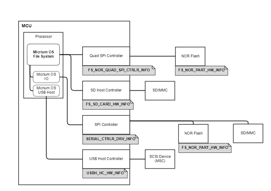
File System Memory Hardware Information#
This section presents the various memory hardware information structures used to configure the different memories (NOR, SCSI and SD). Figure - Memories and their Hardware Information in the File System Memory Hardware Information page gives at a glance the different memories and their associated hardware information structure (in rectangles with a grey background).
Figure - Memories and their Hardware Information#
NOR#
Quad SPI#
The NOR Quad SPI (QSPI) hardware information is a structure of type FS_NOR_QUAD_SPI_HW_INFO. This structure is used by the macro FS_NOR_QUAD_SPI_HW_INFO_REG() to register the NOR QSPI into the Platform Manager . For more information about using the macro FS_NOR_QUAD_SPI_HW_INFO_REG(), refer to the NOR Quad SPI Registration section. The NOR QSPI hardware information structure contain other structures which provide information about the QSPI controller and the NOR flash device. All structures composing the NOR QSPI hardware information structure are explained in the sections below.
Hardware Driver Information#
You need to define the two following structures to fully describe the NOR Quad SPI hardware information:
FS_NOR_QUAD_SPI_CTRLR_INFO (for the QSPI controller)
FS_NOR_PART_INFO (for the NOR flash device)
The following sub-sections give you more details about each structures' field. Listing - Typical NOR Hardware Initialization in the File System Memory Hardware Information page illustrate a typical initialization of the two structures in the file bsp_fs_nor_quad_spi.c.
Listing - Typical NOR Hardware Initialization#
/* Quad SPI controller hardware info. */
const FS_NOR_QUAD_SPI_CTRLR_INFO BSP_FS_NOR_QuadSPICtrl_HwInfo = {
.DrvApiPtr = (FS_NOR_QUAD_SPI_DRV_API *)&FS_NOR_QuadSpiDrvAPI_Silabs_EFM32GG11,
.BspApiPtr = (FS_NOR_QUAD_SPI_BSP_API *)&QuadSPI_Ctrlr_BSP_API,
.BaseAddr = QSPI0_BASE,
.AlignReq = sizeof(CPU_ALIGN),
.FlashMemMapStartAddr = QSPI0_MEM_BASE,
.BusWidth = FS_NOR_SERIAL_BUS_WIDTH_SINGLE_IO
};
/* NOR info composed of QSPI controller & NOR memory chip.*/
const FS_NOR_QUAD_SPI_HW_INFO BSP_FS_NOR_QuadSPI_HwInfo = {
.PartHwInfo.PhyApiPtr = (CPU_INT32U)(&FS_NOR_PHY_MX25R_API),
.PartHwInfo.ChipSelID = 0u,
.CtrlrHwInfoPtr = &BSP_FS_NOR_QuadSPICtrl_HwInfo
};Quad SPI Controller Information#
The Quad SPI driver requires information about the Quad SPI controller on your MCU, which you provide using a structure of type FS_NOR_QUAD_SPI_CTRLR_INFO. Some pieces of information can be found in the MCU's reference manual. Listing - Typical NOR Hardware Initialization in the File System Memory Hardware Information page shows an example of this structure's initialization.
Table - FS_NOR_QUAD_SPI_CTRLR_INFO structure in the File System Memory Hardware Information page describes each configuration field of this structure.
Table - FS_NOR_QUAD_SPI_CTRLR_INFO structure#
Field | Description |
|---|---|
.DrvApiPtr | Pointer to QSPI driver API. |
.BspApiPtr | Pointer to QSPI BSP API. Refer to the next section BSP API Structure for more information. |
.BaseAddr | Base address of the QSPI controller register set. This corresponds to the address of the first register. |
.AlignReq | Buffer alignment requirement if the QSPI controller uses DMA transfers. If no special buffer alignment is required, you may initialize this field to sizeof(CPU_ALIGN). |
.FlashMemMapStartAddr | Start address of the NOR flash range within the microcontroller's internal memory. This field is reserved for future considerations. Must be always DEF_NULL. The Quad SPI controller supports a functional mode called memory-mapped or direct mode. In memory-mapped mode, the external flash memory is mapped in the microcontroller's address space and is seen by the system as if it was internal memory. This mode allows to both access data and execute code from the external flash memory. The memory-mapped mode works with the NOR flash device configured in XIP (eXecute In Place) mode. When the external flash device is memory-mapped, an address range is dedicated to it besides the QSPI registers address range. |
.BusWidth | Width of the serial bus connected between the microcontroller and the NOR flash. Possible values: |
FS_NOR_SERIAL_BUS_WIDTH_SINGLE_IO 1-bit SPI bus | |
FS_NOR_SERIAL_BUS_WIDTH_DUAL_IO 2-bit SPI bus | |
FS_NOR_SERIAL_BUS_WIDTH_QUAD_IO 4-bit SPI bus |
NOR Flash Device Information#
The NOR flash device driver requires information about the NOR memory chip interfaced to your MCU, which you provide using a structure of type FS_NOR_PART_INFO. Listing - Typical NOR Hardware Initialization in the File System Memory Hardware Information page shows an example of this structure's initialization.
Table - FS_NOR_PART_INFO Structure in the File System Memory Hardware Information page describes each configuration field available in this structure.
Table - FS_NOR_PART_INFO Structure#
Field | Description |
|---|---|
.PhyApiPtr | Pointer to NOR PHY driver API. Consult the NOR flash drivers list for more information about the API structure name to use. |
.ChipSelID | NOR chip select ID used by the Quad SOI controller driver to select or unselect the NOR flash device for communication. If the NOR chip is the only device connected to a shared bus, you can specify slave ID #0. |
BSP API Structure#
In order to provide a pointer to the BSP functions needed by the Quad SPI controller driver, you need to create a structure of type FS_NOR_QUAD_SPI_BSP_API. You must define this structure in the NOR QSPI's BSP file (bsp_fs_nor_quad_spi.c).
Table - FS_NOR_QUAD_SPI_BSP_API structure in the File System Memory Hardware Information page describes each field of this structure.
Listing - Example of NOR QSPI BSP API Structure in the File System Memory Hardware Information page shows an example of a BSP API structure.
Listing - Example of NOR QSPI BSP API Structure#
static const ST_QUAD_SPI_BSP_API QuadSPI_Ctrlr_BSP_API = {
.Init = BSP_FS_NOR_QuadSPI_Init,
.ClkCfg = BSP_FS_NOR_QuadSPI_ClkCfg,
.IO_Cfg = BSP_FS_NOR_QuadSPI_IO_Cfg,
.IntCfg = BSP_FS_NOR_QuadSPI_IntCfg,
.ChipSelEn = BSP_FS_NOR_QuadSPI_ChipSelEn,
.ChipSelDis = BSP_FS_NOR_QuadSPI_ChipSelDis,
.ClkFreqGet = BSP_FS_NOR_QuadSPI_ClkFreqGet
};Device Hardware Information#
The last step is to create the main device hardware information structure. This structure encompasses other structures. Listing - Typical NOR Hardware Initialization in the File System Memory Hardware Information page shows an example of this structure's initialization.
Table - FS_NOR_QUAD_SPI_HW_INFO structure in the File System Memory Hardware Information page describes each configuration field of this structure.
Table - FS_NOR_QUAD_SPI_HW_INFO structure#
Field | Description |
|---|---|
.PartHwInfo | Structure describing the NOR flash device characteristics. Refer to section Hardware Driver Information for more details about its fields. |
.CtrlrHwInfoPtr | Pointer to the structure describing the Quad SPI controller characteristics. Refer to section Hardware Driver Information for more details about its fields. |
SCSI#
As mentioned in the note at the beginning of the Memory Controller Types section, an SCSI device is bound to the existence of a USB host. Consequently, SCSI does not have a dedicated hardware information. Instead you need to provide the hardware information for a USB host in order to use the SCSI media driver. Refer to USB Host HCD Hardware Information for more details about providing the USB host hardware information.
SD#
Card#
The SD Card hardware information is composed of a structure of type FS_SD_CARD_HW_INFO. This structure is used by the macro FS_SD_CARD_HW_INFO_REG() to register the SD Card into the Platform Manager . Refer to section SD Card Registration for more details about using the FS_SD_CARD_HW_INFO_REG() macro. The SD Card hardware information structure can contain other structures which provide information about the BSP API, the buffer alignment requirement, etc. All structures composing the SD Card hardware information structure are explained in the sections below.
Hardware Driver Information#
The SD Card media driver requires information about the SD Card controller on your MCU. A structure is not necessary as there is only one piece of information needed. This unique information is:
The buffer alignment requirement. You may need to specify that if the SD Card controller uses DMA transfers. If no special buffer alignment is required, you may initialize this field to sizeof(CPU_ALIGN) .
BSP API Structure#
In order to provide a pointer to the BSP functions for the SD Card memory controller (SDHC) driver, you have to create a structure of type FS_SD_CARD_BSP_API. You must define this structure in the SD Card's BSP file (bsp_fs_sd_card.c).
Table - FS_SD_CARD_BSP_API structure in the File System Memory Hardware Information page describes each field of this structure.
Table - FS_SD_CARD_BSP_API structure#
Field | Description |
|---|---|
.Add | Pointer to the BSP add function. |
.Open | Pointer to the BSP open function. |
.Close | Pointer to the BSP close function. |
.Lock | Pointer to the BSP lock function. |
.Unlock | Pointer to the BSP unlock function. |
.CmdStart | Pointer to the BSP command start function. |
.CmdEndWait | Pointer to the BSP command end wait function. |
.CmdDataRd | Pointer to the BSP command data read function. |
.CmdDataWr | Pointer to the BSP command data write function. |
.BlkCntMaxGet | Pointer to the BSP block count maximum get function. |
.BusWidthMaxGet | Pointer to the BSP bus width maximum get function. |
.BusWidthSet | Pointer to the BSP bus width set function. |
.ClkFreqSet | Pointer to the BSP clock frequency set function. |
.TimeoutDataSet | Pointer to the BSP timeout data set function. |
.TimeoutRespSet | Pointer to the BSP timeout response set function. |
Listing - Example of SD Card BSP API Structure in the File System Memory Hardware Information page shows an example of a BSP API structure.
Listing - Example of SD Card BSP API Structure#
static const FS_SD_CARD_BSP_API BSP_FS_SD_Card_STM32F746G_DISCO_BSP_API = {
.Add = BSP_FS_SD_Card_Add,
.Open = BSP_FS_SD_Card_Open,
.Close = BSP_FS_SD_Card_Close,
.Lock = BSP_FS_SD_Card_Lock,
.Unlock = BSP_FS_SD_Card_Unlock,
.CmdStart = BSP_FS_SD_Card_CmdStart,
.CmdEndWait = BSP_FS_SD_Card_CmdEndWait,
.CmdDataRd = BSP_FS_SD_Card_CmdDataRd,
.CmdDataWr = BSP_FS_SD_Card_CmdDataWr,
.BlkCntMaxGet = BSP_FS_SD_Card_BlkCntMaxGet,
.BusWidthMaxGet = BSP_FS_SD_Card_BusWidthMaxGet,
.BusWidthSet = BSP_FS_SD_Card_BusWidthSet,
.ClkFreqSet = BSP_FS_SD_Card_ClkFreqSet,
.TimeoutDataSet = BSP_FS_SD_Card_TimeoutDataSet,
.TimeoutRespSet = BSP_FS_SD_Card_TimeoutRespSet
};Device Hardware Information#
The last step is to create the main device hardware information structure. This structure contains only pointers to other structures.
Table - FS_SD_CARD_HW_INFO structure in the File System Memory Hardware Information page describes each configuration field of this structure.
Table - FS_SD_CARD_HW_INFO structure#
Field | Description |
|---|---|
.BspApiPtr | Pointer to the BSP API structure you created in the BSP API Structure step. |
.AlignReq | Buffer alignment requirement if SD Card controller uses DMA transfers. Refer to section Hardware Driver Information for more details about this field. |
SPI#
SD SPI does not need a specific hardware information structure. SD SPI relies on the proper hardware information settings for SPI. Refer to SPI Hardware Information for more details about providing the SPI hardware information.
File System Memory Controller Registration to the Platform Manager#
Once the hardware information structure for your memory controller is ready, it must be registered with the Platform Manager . This should normally be done with the BSP_OS_Init() function that is located in the file bsp_os.c.
There are four different macros that you can call to register a memory controller. Table - Memory Controller Register Macros in the File System Memory Controller Registration to the Platform Manager page describes the different macros.
Table - Memory Controller Register Macros#
Macro | Description | Definition Location |
|---|---|---|
FS_NOR_QUAD_SPI_HW_INFO_REG() | Registers a NOR Quad SPI controller communicating with an external NOR flash device. | fs_nor.h |
FS_SD_CARD_HW_INFO_REG() | Registers an SD Card controller (also called SDHC) communicating with an external SD Card in card mode. | fs_sd_card.h |
FS_SD_SPI_HW_INFO_REG() | Registers an external SD communicating with the MCU in SPI mode. | fs_sd_spi.h |
NOR Registration#
Quad SPI#
Listing - Example of NOR Quad SPI Controller Registration in the File System Memory Controller Registration to the Platform Manager page shows an example of how to register a NOR Quad SPI controller.
Listing - Example of NOR Quad SPI Controller Registration#
#include <rtos_description.h>
#if defined(RTOS_MODULE_FS_STORAGE_NOR_AVAIL) (1)
BSP_HW_INFO_EXT(const FS_NOR_QUAD_SPI_CTRLR_INFO, BSP_FS_NOR_QuadSPI_HwInfo);
#endif
void BSP_OS_Init (void)
{
/* ... */
/* ------- REGISTER MEMORY CONTROLLERS ------- */
#if defined(RTOS_MODULE_FS_STORAGE_NOR_AVAIL) (2)
FS_NOR_QUAD_SPI_HW_INFO_REG("nor0", &BSP_FS_NOR_QuadSPI_HwInfo);
#endif
}(1) Since the global variable for NOR hardware information is defined in another file, you must declare it as external in your bsp_os.c file. Always use the BSP_HW_INFO_EXT() macro.
(2) Registering a NOR Quad SPI controller with the tag "nor0". The tag will be used internally by the File System stack later on when calling the function FSStorage_Init(). The NOR hardware information structure is described in the NOR Quad SPI section of the Hardware Information page.
SCSI Registration#
As mentioned in the note at the beginning of the Memory Controller Types section, an SCSI device is bound to the existence of a USB host. Consequently, SCSI does not have a dedicated register macro. Instead you need to use the USB host register macro described in USB Host Controller Registration to the Platform Manager .
SD Registration#
SD Card#
Listing - Example of SD Card Controller Registration in the File System Memory Controller Registration to the Platform Manager page shows an example of how to register an SD Card (SDHC) controller.
Listing - Example of SD Card Controller Registration#
#include <rtos_description.h>
#if defined(RTOS_MODULE_FS_STORAGE_SD_CARD_AVAIL) (1)
BSP_HW_INFO_EXT(const FS_SD_CARD_HW_INFO, BSP_FS_SD_Card_HwInfo);
#endif
void BSP_OS_Init (void)
{
/* ... */
/* ------- REGISTER MEMORY CONTROLLERS ------- */
#if defined(RTOS_MODULE_FS_STORAGE_SD_CARD_AVAIL)
FS_SD_CARD_HW_INFO_REG("sd0", &BSP_FS_SD_Card_HwInfo); (2)
#endif
}(1) Since the global variable for SD Card hardware information is defined in another file, you must declare it as external in your bsp_os.c file. Always use the BSP_HW_INFO_EXT() macro.
(2) Registering an SD Card (SDHC) controller with the tag "sd0". The tag will be used internally by the File System stack later on when calling the function FSStorage_Init(). The SD Card hardware information structure is described in the SD Card section of the Hardware Information page .
SD SPI#
Listing - Example of SD SPI Controller Registration in the File System Memory Controller Registration to the Platform Manager page shows an example of how to register an SD Card controller and an SD using an SPI controller.
Listing - Example of SD SPI Controller Registration#
#include <rtos_description.h>
#ifdef RTOS_MODULE_IO_SERIAL_AVAIL (1)
BSP_HW_INFO_EXT(const SERIAL_CTRLR_DRV_INFO, BSP_Serial_SiliconLabs_Bus0_DrvInfo);
#endif
void BSP_OS_Init (void)
{
/* ... */
/* ------- REGISTER MEMORY CONTROLLERS ------- */
#if defined(RTOS_MODULE_IO_SERIAL_AVAIL)
IO_SERIAL_CTRLR_REG("spi0", &BSP_Serial_SiliconLabs_Bus0_DrvInfo); (2)
#endif
#if defined(RTOS_MODULE_FS_STORAGE_SD_SPI_AVAIL)
FS_SD_SPI_HW_INFO_REG("sd0", "spi0", 0u); (3)
#endif
}(1) Since the global variable for SPI hardware information is defined in another file, you must declare it as external in your bsp_os.c file. Always use the BSP_HW_INFO_EXT() macro.
(2) Registering an SPI controller with the tag "spi0". The tag will be used later on when calling the function SPI_BusAdd() . The SPI hardware information structure is described in SPI Hardware Information .
(3) Registering an SD in SPI mode with the tag "sd0". The tag will be used internally by the File System stack later on when calling the function FSStorage_Init(). You need to indicate the SPI controller tag, "spi0" in this case, to which the SD is interfaced to. The third macro parameter specifies a slave ID in case there are other slaves connected to the same SPI bus besides SD.