Getting Started with Development#
This section assumes that you have downloaded SSv6, Simplicity Studio Extension for VS Code and the Silicon Labs OpenThread SDK, and are familiar with the features of the SSv6 Launcher perspective.
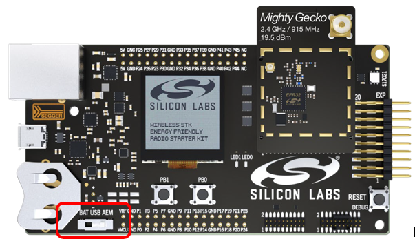
The mainboard should be connected.
Note: For best performance in Simplicity Studio, be sure that the power switch on your mainboard is in the Advanced Energy Monitoring or "AEM" position, as shown in the following figure.
In these instructions you will compile and load a simple ot-cli-ftd application on two nodes. Section Creating a Network describes how to use the examples to create a network. Section Network Analyzer describes how to use Network Analyzer to observe traffic across the network.
When working with an example application in Simplicity Studio, you will be executing the steps in the following order:
Create a project based on an example.
Configure the project.
Build the application image and flash it to your device.
These steps are described in detail in the following sections. These procedures are illustrated for a mainboard with an EFR32MG24.
Note: Your SDK version may be later than the version shown in the figures.
Creating a Project Based on an Example#
Simplicity Studio (SSv6) offers a variety of ways to begin a project using an example application. The online Simplicity Studio 6 User's Guide, available both through Simplicity Studio 6 User's Guide and in the Learn & Support section on the Home page of SSv6. This guide uses the Start A New Project on the Home page, because it takes you through all three of the Project Creation Dialogs.
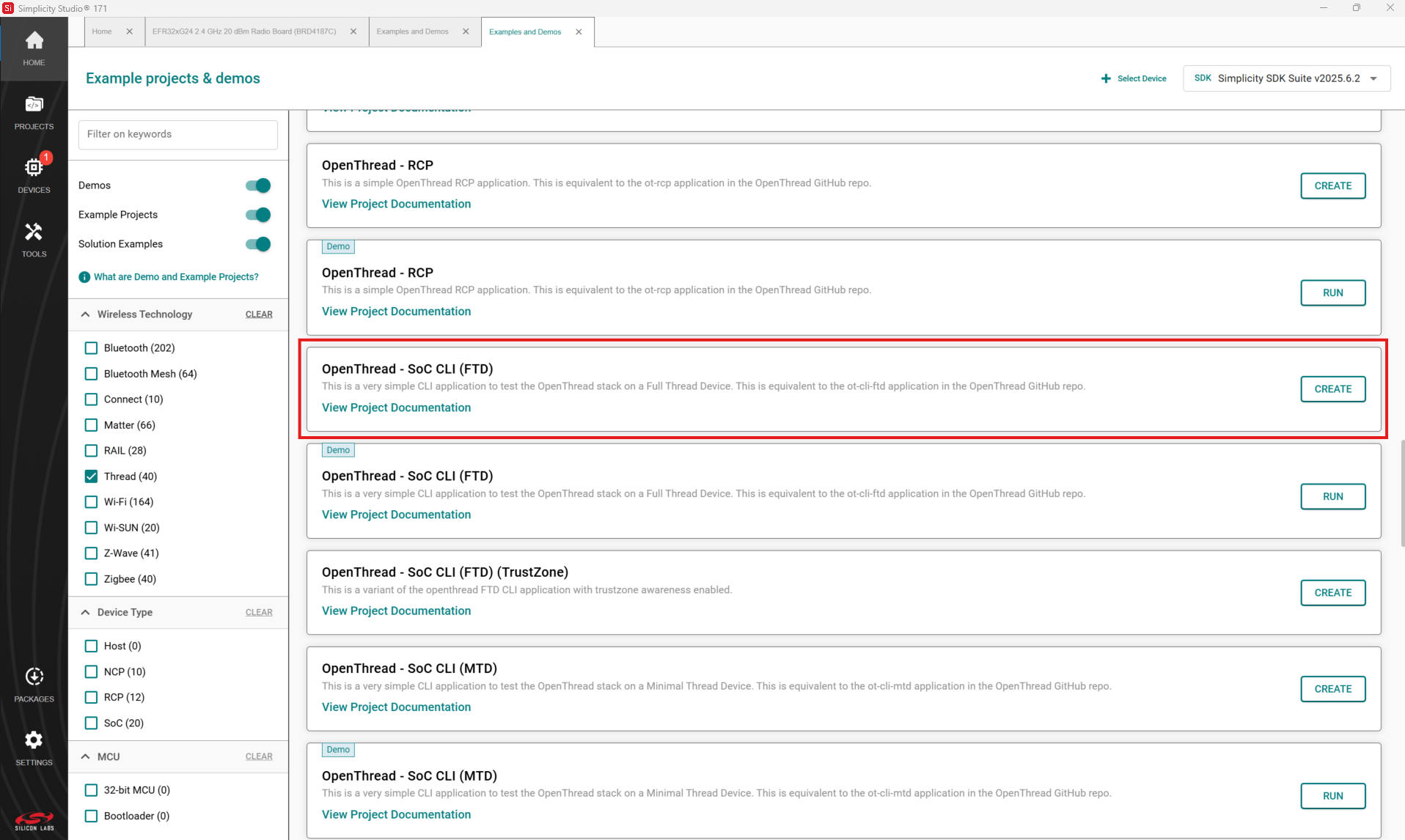
The Example Project Selection dialog opens. Use the ‘Thread’ Technology Type and Keyword filters to search for a specific example, in this case OpenThread – SoC CLI (FTD). Select it and click CREATE.
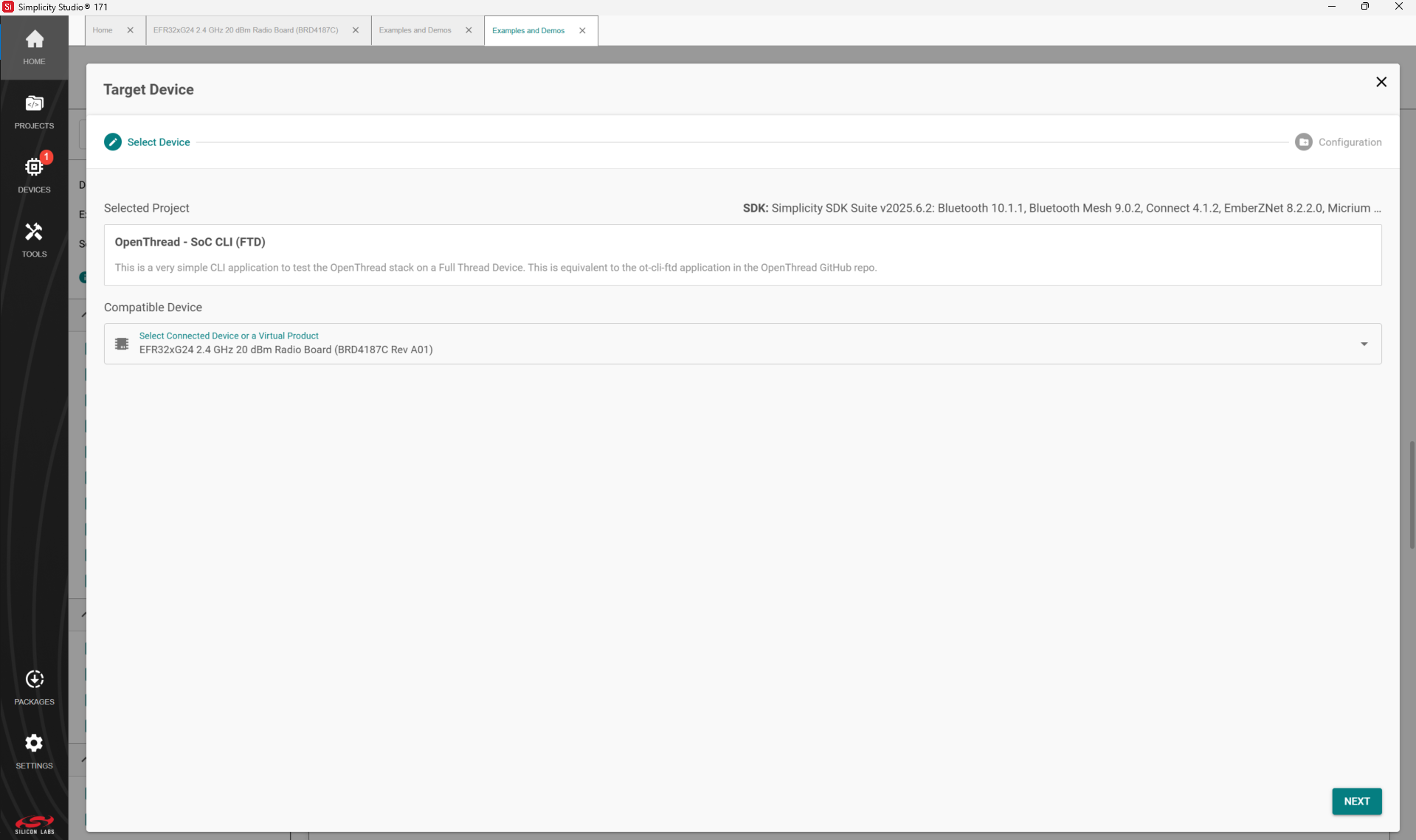
Select Compatible Device and click NEXT.
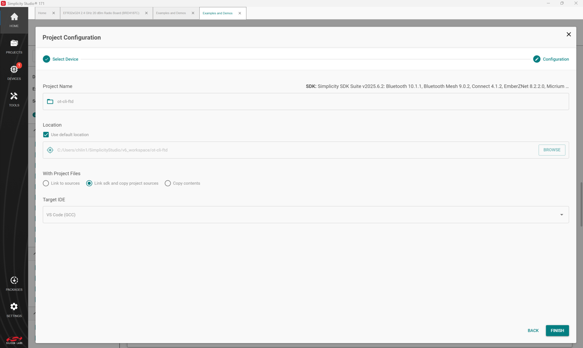
The Project Configuration dialog opens. Here you can rename your project, change the default project file location, and determine if you will link to or copy project files. Note that if you change any linked resource, it is changed for any other project that references it. Do not change the default VS Code GCC toolchain supported by OpenThread. Click FINISH.
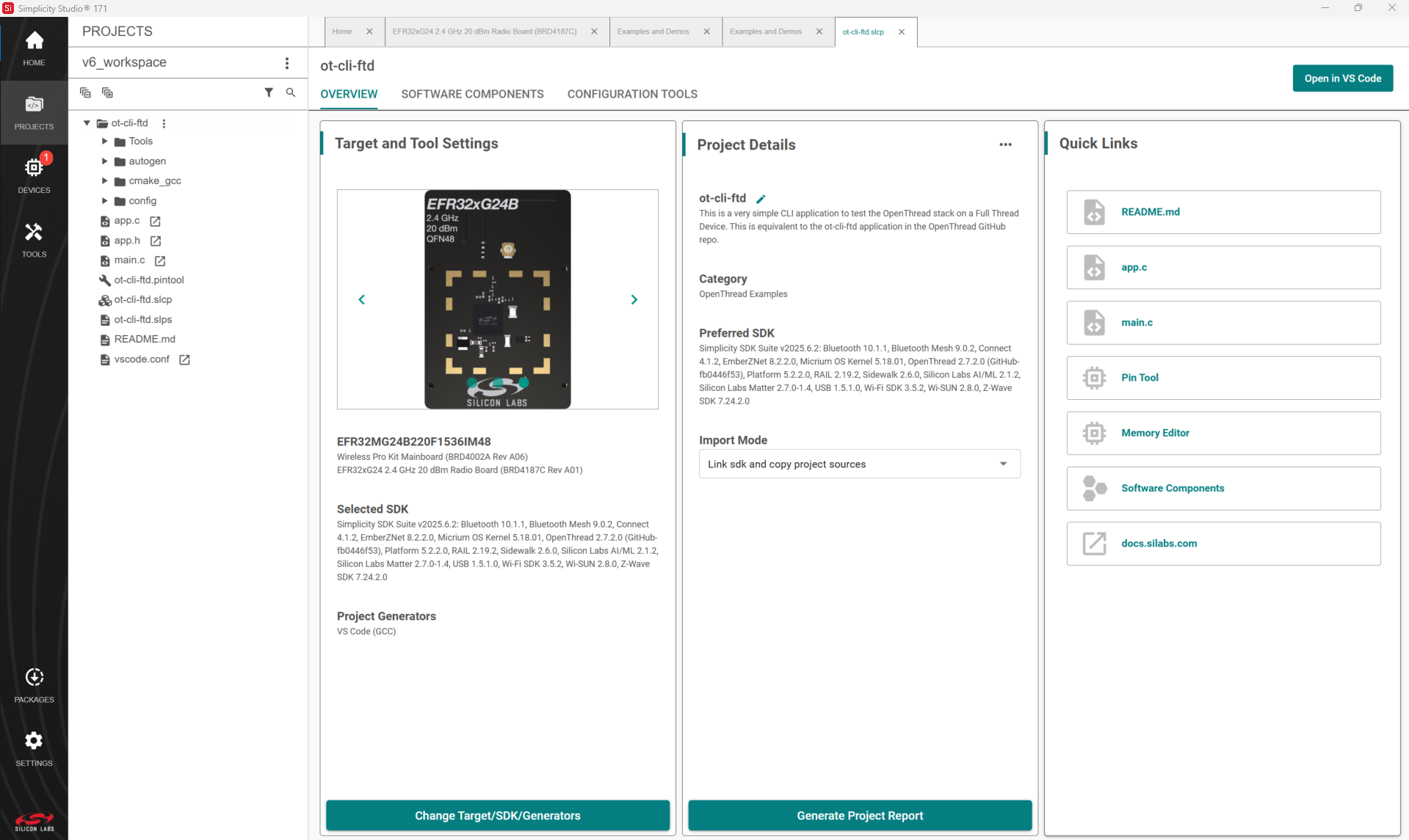
The SSv6 Perspective opens with a description of the project on a readme tab. Click the <project>.slcp tab to open the Project Configurator’s OVERVIEW tab. See the online Simplicity Studio 6 User’s Guide for details about the functionality available through the SSv6 perspective and the Project Configurator.
Configuring the Project#
Silicon Labs OpenThread applications are built on a Gecko Platform component structure. Click the SOFTWARE COMPONENTS tab to see a complete list of Component categories.
Note: All EFR32 parts have a unique RSSI offset. In addition, board, antenna and enclosure design can also impact RSSI. When creating a new project, install the RAIL Utility, RSSI component. This feature includes the default RSSI Offset Silicon Labs has measured for each part. This offset can be modified if necessary after RF testing of your complete product.
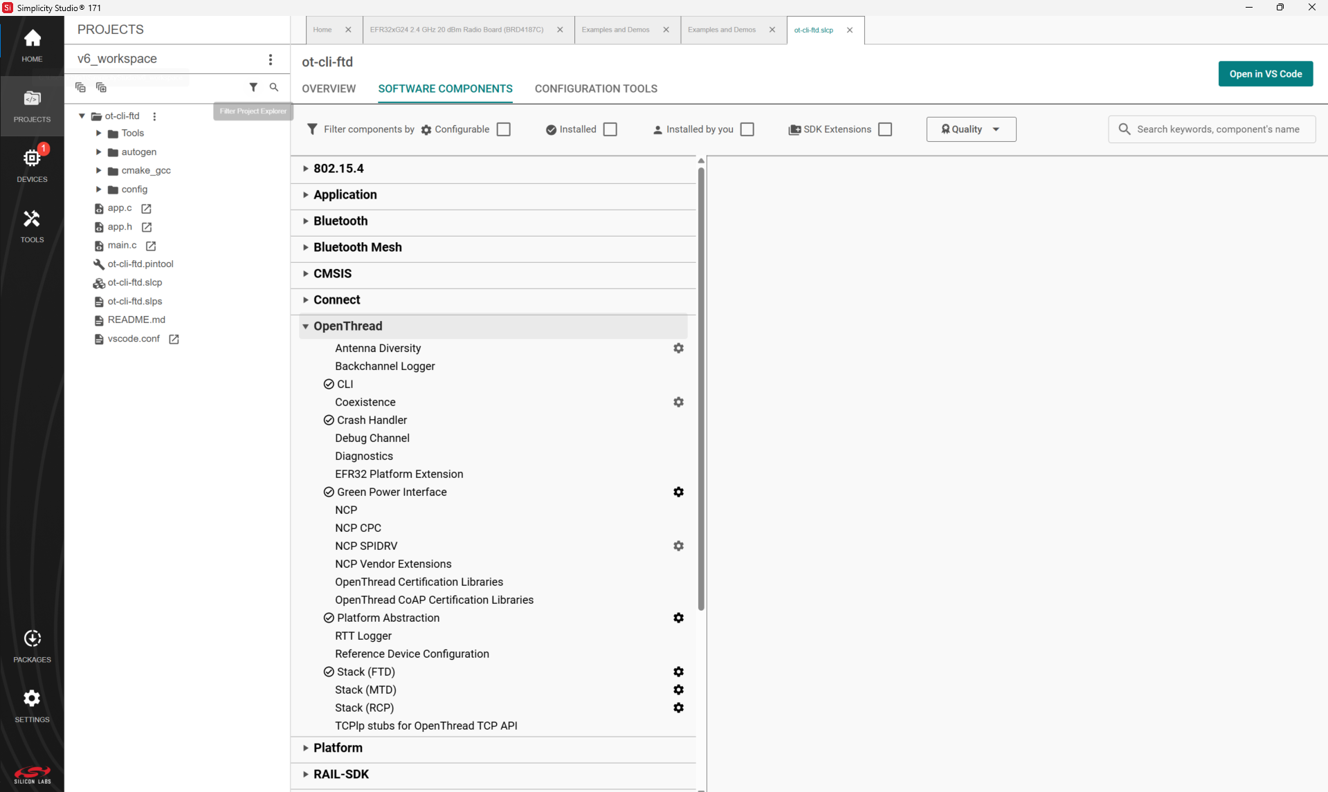
The project is configured by installing and uninstalling components, and configuring installed components. Installed components are checked. Click Installed Components to see a filtered list of components installed by the example application.
Configurable components have a gear symbol. Select a component to see information about it.
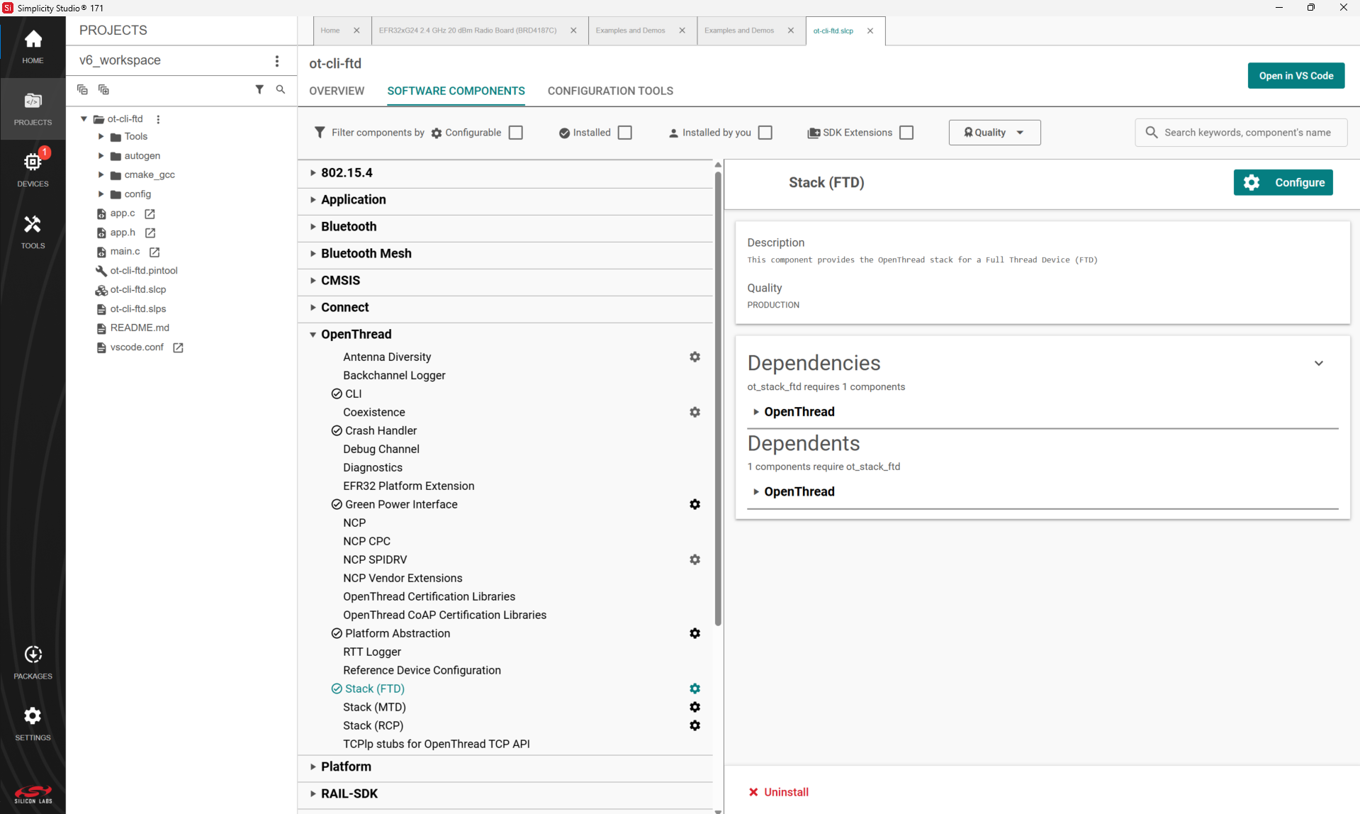
If the component is configurable, click CONFIGURE to open the Component Editor.
For example, in the Stack (FTD) component you can enable or disable various stack functions. These are equivalent to build options that can be specified to the makefile when building the sample applications in GitHub.
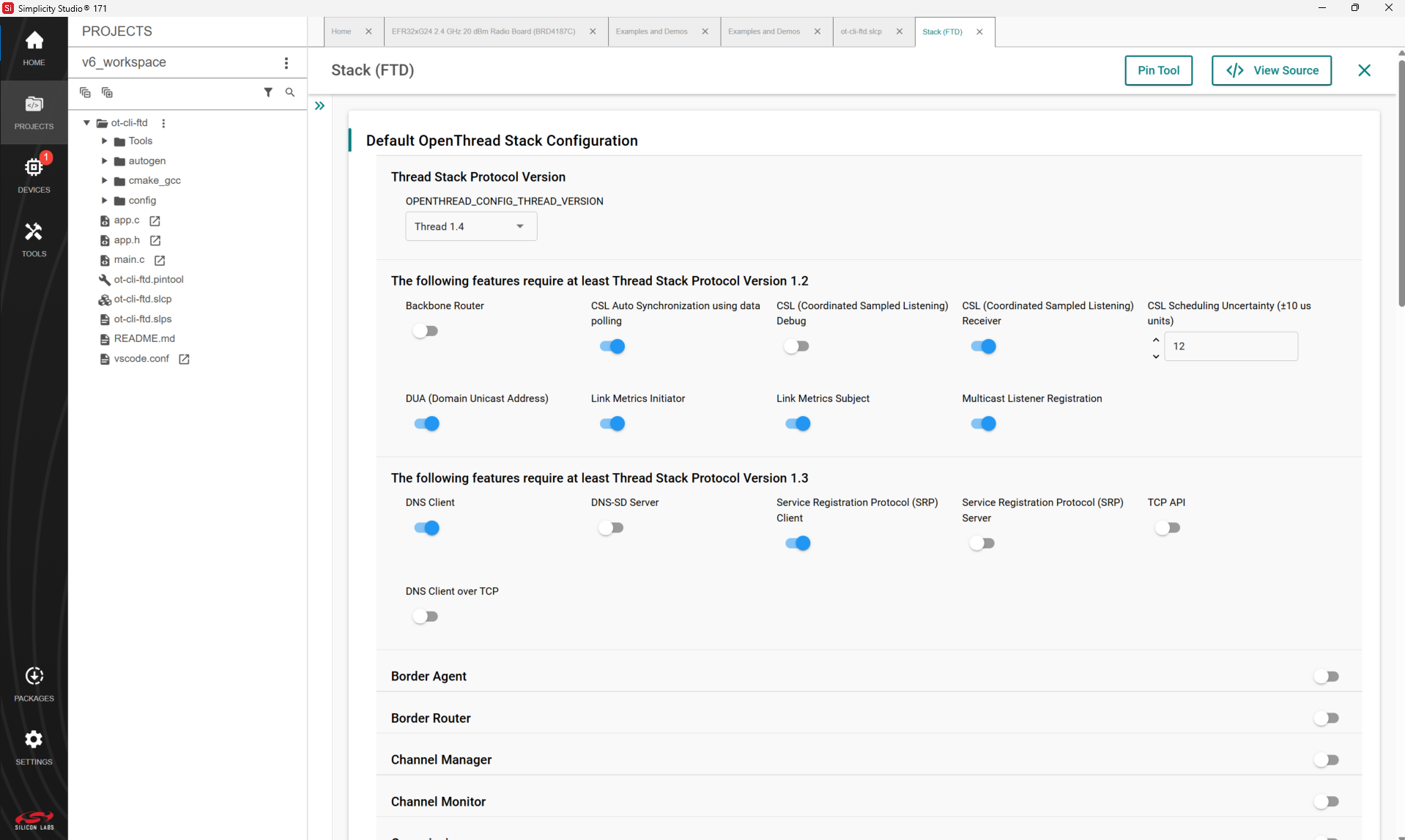
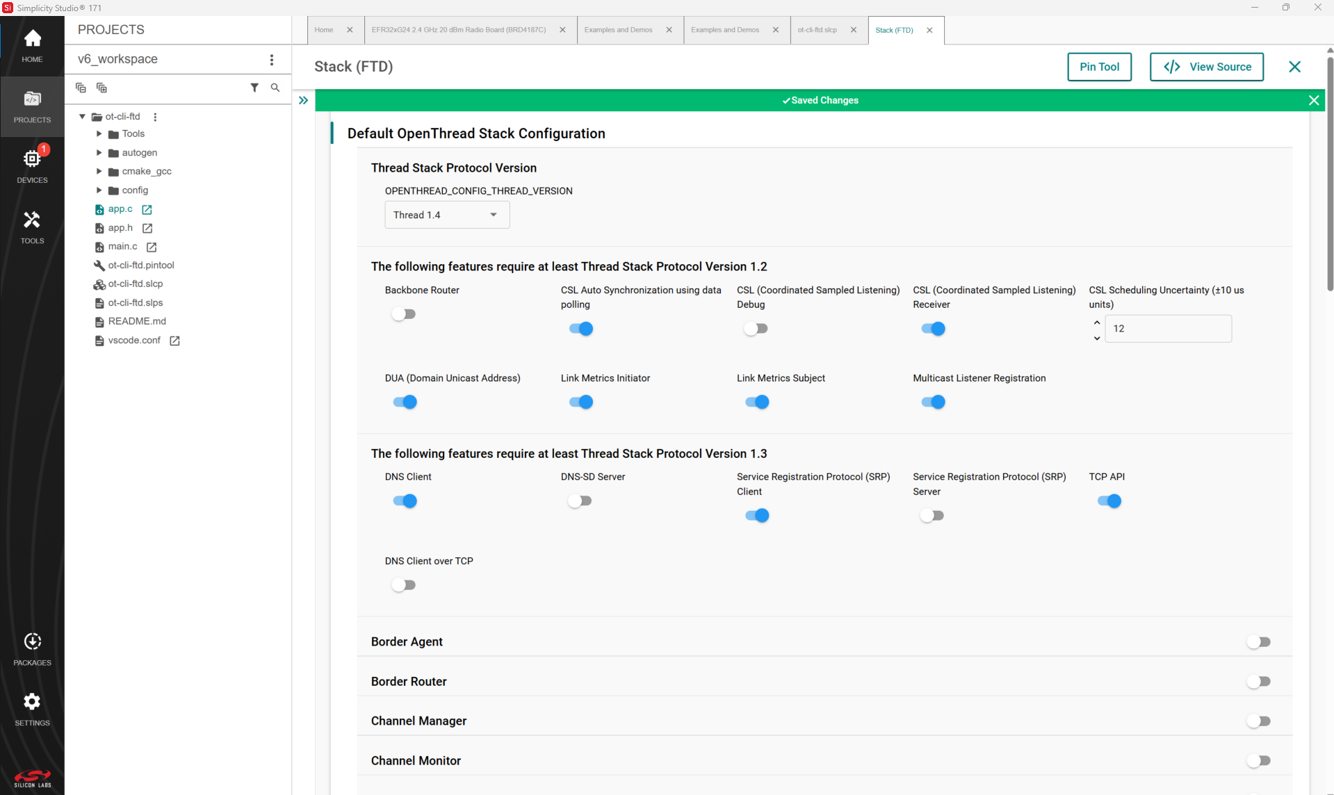
Any changes made are autosaved, and project files are autogenerated.
Building the Project#
You can either compile and flash the application automatically, or manually compile it and then flash it.
Automatically Compile and Flash#
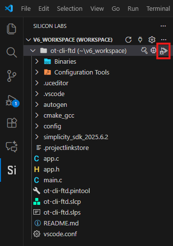
You can automatically compile and flash the application to your connected development hardware in the Simplicity Studio Extension for VS Code. Click the Debug control.
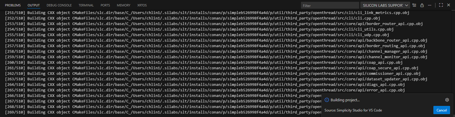
Progress is displayed in the console.
When building and flashing are complete a Debug perspective is displayed. Click the Resume control to start the application running on the device.
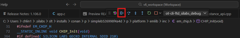
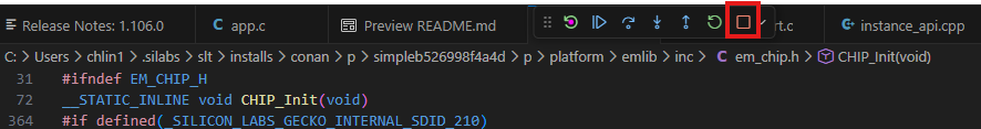
Next to the Resume control are Suspend, Disconnect, Reconnect, and stepping controls. Click Disconnect when you are ready to exit Debug mode.
Manually Compile and Flash#
After you generate your project files, instead of clicking Debug in the Simplicity Studio Extension for VS Code, click the Build control (hammer icon).
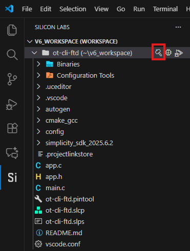
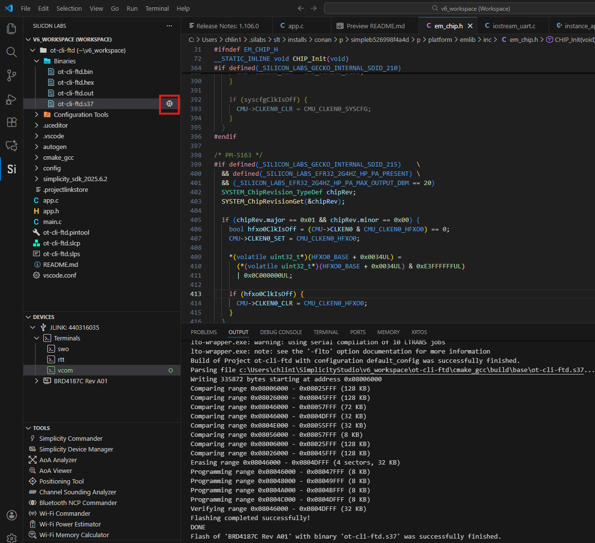
You can load the binary image through Project Explorer view.
Locate the <project>.bin, .hex, or .s37 file in the compiler subdirectory.
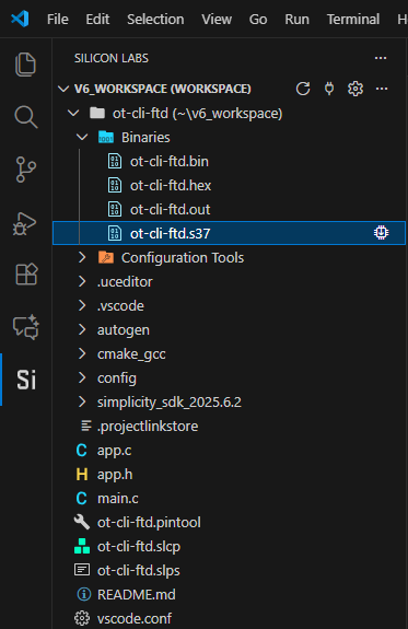
Click Flash. The process will be displayed in the Output Console.
Flashing a Bootloader#
All Silicon Labs examples require that a bootloader be installed. By default, a new device is factory-programmed with a dummy bootloader. If you have a new device, haven’t cleared the bootloader region for your part or have a supported bootloader image already flashed on your device, skip this step and continue with the next section.
With Silicon Labs OpenThread, the bootloader serves to start the application code within the image you created and flashed in the previous procedure. Once you have installed a bootloader image, it remains installed until you erase the bootloader region for your device.
If you need to flash a bootloader, select a bootloader example and build and flash it as you would any application. See UG266: Silicon Labs Gecko Bootloader User’s Guide for GSDK 3.2 and Lower, Silicon Labs Gecko Bootloader User’s Guide for GSDK 4.0 and Higher, or Silicon Labs Gecko Bootloader User’s Guide for Series 3 and Higher for more information.
Creating a Network#
Depending on the example application, you may be able to interact with it through your development environment’s Console interface using a CLI (command line interpreter). The console interface allows you to form a network and send data.
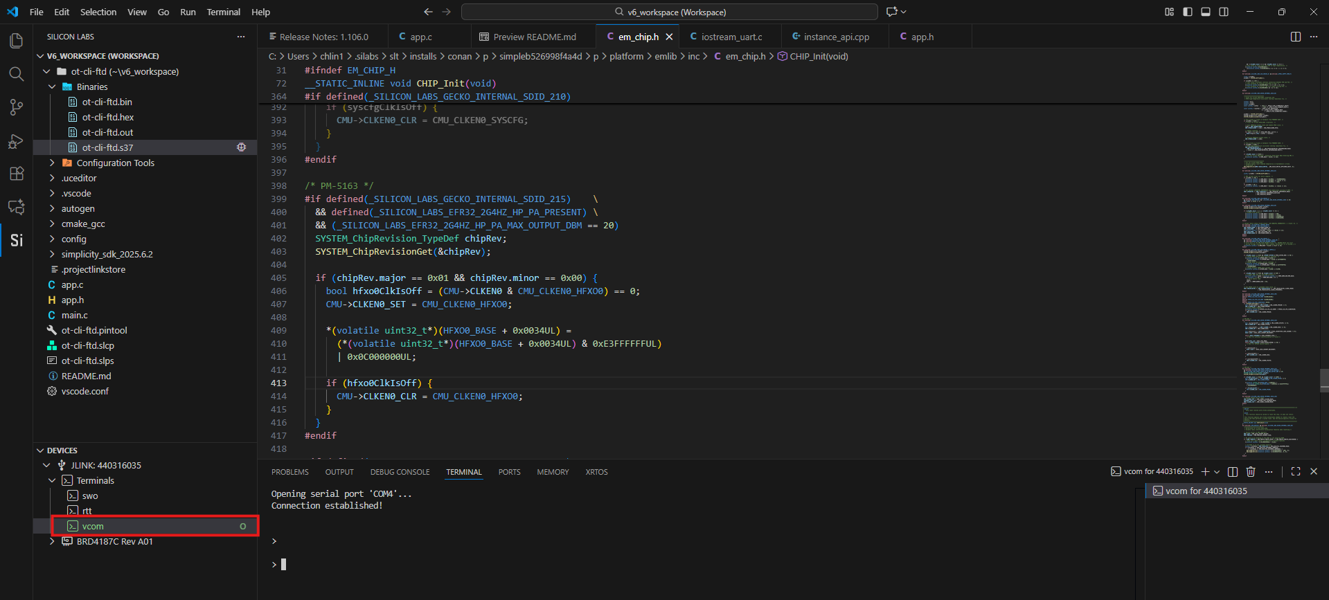
To launch the Console interface, double-click vcom in the Simplicity Studio Extension for VS Code perspective.
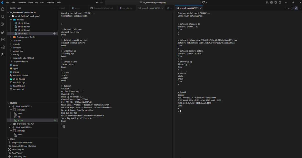
To create a two-node network using the ot-cli-ftd example, flash the ot-cli-ftd.s37 application image on two separate nodes. Launch the console for the two nodes and execute the commands given below:
Form a network#
On Device A, enter:
> dataset init new
Done
> dataset commit active
Done
> ifconfig up
Done
> thread start
DoneThe previous commands should initialize the node with new network parameters and form a network. Check the status of the node after a few seconds by executing the following command. The node should now be a leader.
> state
leader
DoneCheck the network parameters by running the following command:
> dataset
dataset
Active Timestamp: 1
Channel: 18
Channel Mask: 07fff800
Ext PAN ID: 4e08d5129185b233
Mesh Local Prefix: fda6:83fa:7cc1:e809/64
Master Key: d5bf78c4bbd96605c6e55a32fa2c03ab
Network Name: OpenThread-21ec
PAN ID: 0x21ec
PSKc: 3be0de54e5d0f2cd5622de0716680588
Security Policy: 0, onrcb
DoneAttach a second node (device B) to the network#
Note: Depending on the network parameters generated by node A (as seen above), update the channel number and the master key in the following commands.
On Device B enter:
> dataset channel 18
Done
> dataset networkkey d5bf78c4bbd96605c6e55a32fa2c03ab
Done
> dataset commit active
Done
> ifconfig up
Done
> thread start
DoneThe above commands should cause the node to attach to the network started by node A. Check the status of the node after a few seconds by executing the following command. The node should now be a child (which will eventually update to a router).
> state
child
DoneTest network connectivity#
For this step, compute Node B’s IP addresses and ping it from Node A as follows.
On device B enter:
> ipaddr
ipaddr
fda6:83fa:7cc1:e809:0:ff:fe00:e000
fda6:83fa:7cc1:e809:8a39:6c2d:e3d:ea61
fe80:0:0:0:e443:b790:285b:2f5f
DoneOn node A enter:
> ping fe80:0:0:0:e443:b790:285b:2f5f
ping fe80:0:0:0:e443:b790:285b:2f5f
Done
>
> 16 bytes from fe80:0:0:0:e443:b790:285b:2f5f: icmp_seq=2 hlim=64 time=21msThe following figure shows the console at the end of the procedure.