Transmission Test#
Transmitted Signal Types#
The device is capable to generate continuous unmodulated signal (CW mode, also referred as single tone or sinus wave signal), packets (packet mode) and a continuous pseudo random stream (PN9 mode). The following table helps to decide which transmission mode should be used for a corresponding measurement.
CW mode | PN9 mode | Packet mode | |
|---|---|---|---|
Tx Power | x | ─ | ─ |
Power Spectral Density Mask | ─ | x | ─ |
Phase Noise | x | ─ | ─ |
Spurious Emission | x | ─ | ─ |
Transient Power | ─ | ─ | x |
The following sections describe how to turn these modes on, and how to modify some corresponding parameters to customize the output signal.
Output a Continuous Unmodulated Tone#
CW mode is used to test the output power of the test card and observe the unmodulated carrier spectrum. In this mode, only the frequency and the output power are configurable parameters. There are two modes for CW generation. One is designed to generate CW signal [tone] with the best possible quality. The other is specifically designed to measure phase noise of the device [phaseNoise]. For more information on phase noise measurement, see Phase Noise Measurement. The difference between these two modes of CW signal generation is the PLL bandwidth settings. In the [phaseNoise] CW mode, the PLL bandwidth is the same as the current radio settings. With this method the generated CW signal provides information on how the PLL behaves when transmitting packets during operation.
Note: Before setting power and some other parameters, the device must be in idle receiver mode, by calling rx 0 .
Set Receiver to Idle:
rx 0 {{(rx)}{Rx:Disabled}{Idle:Enabled}{Time:539309681}}Enable CW Mode:
setTxStream 1 0 [enable] [streamMode] Enable(1 0) or Disable(0 0) a CW tone from the radio.The command above also sets the PLL bandwidth to narrower than it's set on the actual radio configuration to produce better quality CW tone.
Enable CW Signal for Phase Noise Measurement:
setTxStream 1 3 [enable] Enable(1 3) or Disable(0 3) a tone from the radio with the same PLL bandwidth as the current PHY configuration.Set Tx Power:
The setPower command can be used to change the output power; enter the desired power in deci dBm.
Note: You can check the Tx power limitation with the
getPowercommand. The radio state must be IDLE for Rx and Tx side. Callrx 0andSetXxTone 0first.
setPower s [power] Set the current transmit power in deci dBmSet Channel:
A way to change the frequency is to change the channel. The specific channel configuration depends on the PHY configuration you have chosen for your test app. To switch between channels, use the setChannel [num] command. In addition, you can use button PB1 to cycle between channels. (The channel spacing value is used for relative frequency configuration to configure a frequency so many channel spacing away from the base channel frequency.)
To get the current radio channel, use this command:
getchannel Get the current radio channelTo set another radio channel, use this command:
setchannel u Set the current radio channelSet Frequency:
To modify the frequency to a value not defined in the channel list, set the application into the FREQUENCY_OVERRIDE debug mode via debugMode, which tells the application to ignore the current channel selection. Once in the FREQUENCY_OVERRIDE debug mode, you can use the freqOverride command to switch to another center frequency.
Note: The
freqOverridecommand requires you to be in FREQUENCY_OVERRIDE debug mode.
Note: The radio state must be IDLE in order for the channel to be changed or the frequency to be modified. Call
rx 0first.
Example:
rx 0 [enable] Enable(1) or Disable(0) receive mode
setDebugMode 1 [mode] 1 = Frequency Override. 0 = Disable debug mode
freqOverride 2404000000 [freq] Change to freq specified in Hz. Requires debug mode to be enabled.Set Different PHY Configuration:
To switch between PHYs in a multi PHY configuration, use the setConfigIndex command.
Example:
> setConfigIndex 0
{{(setConfigIndex)}{configIndex:0}{firstAvailableChannel:0}}Output a Continuous Modulated PN9 Stream#
In this mode, the modulation content is generated internally using a pseudo-random (PN9 sequence) bit generator. The primary purpose of this mode is to observe the modulated spectrum without having to provide data for the radio. This mode is usually used to test the power spectral density mask.
In this mode, only the frequency and the output power are configurable parameters. To change these parameters, refer to Output a Continuous Unmodulated Tone.
Enable PN9 mode:
setTxStream Enable/Disable a PN9 stream from the radioOutput Packets#
The application starts in packet mode with the receiver enabled. In this mode we receive and transmit packets using the radio's frame controller hardware.
To transmit a specified number of packets, use this command:
tx w [n] Transmit n packets. If n is 0 transmit infinitelyOr press button PB0. If you hold PB0 for a couple of seconds or run the tx 0 command, you can toggle the continuous transmit mode.
In this mode, the frequency, the output power, delay in between each transmitted packet, the length, and the value of the bytes to send are configurable parameters. To change the frequency and the output power parameters, refer to Output a Continuous Unmodulated Tone.
When transmitting multiple packets or infinite packets there is a configurable delay in between each transmit. By default this is 250 ms, but it can be set with the following command:
setTxDelay w [delay] Set the inter-packet delay in milliseconds for repeated TxGet the inter-packet delay in milliseconds for repeated Tx, use the getTxDelay command.
If the desired delay is lower than you can set with setTxDelay, all the peripherals must be disabled to improve performance.
setPeripheralEnable u [enable] Turn LEDs and LCD on/offThe application by default sends a fixed packet, but it is possible to override the values via setTxPayload. The command allows you to modify the values of the payload at specific offsets. For instance to modify the first 4 bytes sent in the packet to be 0x01 0x02 0x03 0x04, this is the command:
setTxPayload 0 0x01 0x02 0x03 0x04Note: To view the currently configured TX Packet information, use the following command:
printTxPacket Print the current Tx data and lengthA byte in the payload holds the length of the packet for variable length schemes. The length byte in IEEE 802.15.4 is the first byte; this is what you can set using the setTxPayload command. The length byte also covers the CRC length of the packet, and the length parameter covers the length byte; this is what you can set using the setTxLength command.
All in all, here is an example to set 3-byte payload to 0x01 0x02 0x03, while using IEEE 802.15.4 configuration:
setTxLength 4
setTxPayload 0 0x05 0x01 0x02 0x03A spectrum analyzer is used to view the over the air sent packets of the radio. It must be connected through a proper RF cable to the RF connector of the radio board.
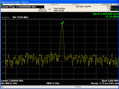
Tx Power Measurement#
A common way to measure the transmitted power of a device is to transmit a CW signal, then measure the transmitted signal with a spectrum analyzer or an RF power meter device. The measurements should be conducted, and proper RF cabling is necessary.
A spectrum analyzer is used to measure the transmit performances of the radio and must be connected through a proper RF cable to the RF connector of the radio board. In this example the transmitted power is measured in the CW signals 5MHz frequency range and the CW signal is marked with a marker (Mkr 3). The transmitted power is displayed on the right upper corner, where the marker is placed.
Power Spectral Density Mask Measurement#
Power Spectral Density (PSD) gives feedback about the transmitted signal's spectrum usage. PSD is usually measured with a PN stream. However, Silicon Labs recommends measuring the device's PSD by enabling the PN9 stream. A spectrum analyzer is used to measure the power spectral density mask of the radio and must be connected through a proper RF cable to the RF connector of the radio board. RF cable loss should be compensated for accurate Tx power output level measurement. The proper reference level and span of the device is required as well.
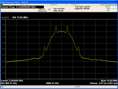
The figure above shows the demodulated signal when the radio board works in PN9 mode. The data rate is 1 Mbps; the deviation is 500 kHz, and the modulation type is 2GFSK.
Phase Noise Measurement#
Phase noise (PN) is a frequency domain representation of a signal's jitter. Phase noise is usually measured when a reference signal's quality is specified. PN measurement gives a feedback on how the - ideally - stable reference signal or other CW signal's frequency changes in a short period of time. PN is usually represented as a frequency-amplitude graph or a notable point - from the graph - is presented in dBc/Hz.
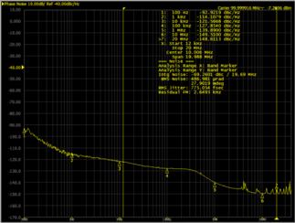
Phase noise is measured with a spectrum analyzer, optimally one with a phase noise measurement feature. Proper connectors and cables are obligatory for this measurement. The PN graph usually contains only one side of the center frequency, as both sides are nearly identical. Frequency is usually represented logarithmically.
EFR32 devices' phase noise is usually measured, giving a feedback of the carrier's quality. If PN is measured on an EFR device, a CW signal is transmitted for measuring. PN not only effects the Tx performance but also the Rx side. The PN gives feedback on the oscillator quality, hence the transmit side and receiver side are affected as well. High PN on the transmitter side results in bad EVM and on the receiver side results in poor sensitivity, as PN is added to the noise level.
Note: Use RAILtest's special CW mode for phase noise measurement described in Output a Continuous Unmodulated Tone.
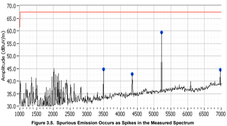
Spurious Emission Measurement#
Spurious emissions are unwanted emissions at frequencies other than those of the transmitted channel. Spurious emission measurement is done by measuring the observed (transmitted) channel and its' neighbor while transmitting packets. A spectrum analyzer is used for measuring and at each frequency at which a spurious component is detected, the power level is measured and noted. The measured frequency bandwidth is typically2-10X as the occupied channel bandwidth. Some RF spectrum analyzers have a spurious emission measurements feature, to make performing these measurements easier. Spurious measurements are often taken while standard packets are transmitted, but some region's standard requires a different type of transmitted signal.
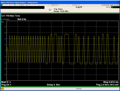
Transient Power#
Transient power is power appearing in frequencies other than the occupied channel when the transmitter is turned on or off. Transient power is expressed in dBm and measured at specific offset frequencies from the carrier. Standards usually describe offset frequencies with a maximum tolerated power of transient power.
Transient power can be measured with a spectrum analyzer, used in zero span mode. Zero span mode is used to measure a specific frequency. By changing the resolution bandwidth parameter of the analyzer, the measured frequency region can be set. A higher resolution bandwidth enables acquiring a wider frequency region, and allowing more power to the analyzer.
The EFR32 device is used in packet mode and sent at least 5 to 10 packets. The spectrum analyzer must be set to measure all of them with one measurement, by changing measurement / sweep time. After measurement the peak value must be recorded.
The following is an example of the measurement.
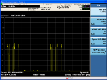
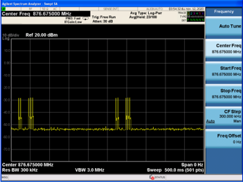
The first figure is a measurement at 78 kHz and the second is at 1275 kHz offset from the carrier frequency of the signal. The signal's power is 16 dBm. The measurement shows that at both settings the maximum power is around -28 to -30 dBm. It is important to take in account that the resolution bandwidth (RBW) is not the same at the two measurements and this should be compensated in some cases. In this case, the power density at the second measurement must be less than the first one, but a wider frequency range is measured. Larger RBW result in more power being received at the wider frequency range.
Enable Direct Mode#
In direct mode, the radio will still attempt to decode received packets, but the data bit streams are input to and output from the chip in real-time on a physical I/O pin. This is often useful in legacy systems that do not use a conventional packet structure, or when the host MCU must perform customized packet handling or processing. In TX Direct mode, the TX modulation data is applied to an input pin of the chip and processed in 'real time' (that is, not stored in a register for transmission at a later time).
The GPIOs for direct mode are fixed for now to the following pins.
DIN - EFR32_PC10 -> EXP_HEADER15/WSTK_P12
DOUT - EFR32_PC11 -> EXP_HEADER16/WSTK_P13The data on these pins is asynchronous and can be connected directly to a UART. To enter direct mode issue the directMode 1 command after starting the app. To leave direct mode use directMode 0. To transmit, enable the transmitter by issuing directTx 1 and later stop it with directTx 0. Receive is controlled using the standard rx 1/0 command, but is enabled by default when not transmitting.
In this mode, only the frequency and the output power are configurable parameters. To change these parameters, refer to Output a Continuous Unmodulated Tone.