Reception Test#
Packet Error Rate (PER) and Bit Error Rate (BER) are error ratios that could measure various reception tests
PER | BER | |
|---|---|---|
Rx sensitivity | triggered and non-triggered | x |
Selectivity | x | x |
Blocking | x | x |
Intermodulation | x | x |
Maximum input Power | x | x |
EFR devices have a special mode to measure BER, with additional functions that can be used to calculate and measure BER easily. However, Silicon Labs does not recommend using this mode for RF evaluation, as regular frame detection does not occur in this mode. Instead, measuring PER with the normal operational mode turned on is recommended. Measuring PER gives more accurate feedback about how the EFR radio configuration perform, as it is testing in a mode that will be operational in the field after deployment.
PER Measurement#
Basics of the Packet Error Rate#
To measure PER, the accurate packet symbols must be known. PER [%] is calculated by the following:
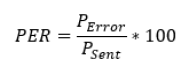
where#
Perror = the number of packets not received correctly
Psent = the number of packets sent and the result is displayed as a percentage.
PER measurement requires an accurate device that is able to send the packets the receiver under test (RUT) expects to receive. An RF vector signal generator is a good fit for these measurements.
Typical PER measurement procedure using RAILtest:
Record the packet that should be transmitted to the RUT (receiver under test) and load it to the RF signal generator.
Connect the RF signal generator and the RUT with the proper RF cable.
Send 100 to 1000 packets to the RUT. (P sent)
View the received number of packets by using
status(RAILtest) command for example. The RxCount value gives the successfully received number of packets. (P sent - packets received = P error)Calculate PER.
Using the status command, RxCount is the number of successfully received packets. SyncDetect is the number of sync word detection and FrameErrors is the number of CRC errors acquired.
Record a Transmitted Packet#
To know how a packet is assembled on an EFR32 device, it is practical to record a transmitted packet. A packet can be captured and demodulated with an RF vector spectrum analyzer from the EFR32 device's RF port, or the transmitted symbols could be wired to a GPIO pin before being sent to the modulator. The second option offers an easy way to see the transmitted baseband packet symbols before the modulation and upconversion to RF frequencies.
To port the transmitted packet symbols to the GPIO port, the PRS channels should be configured by using the setDebugSignal command. Use the setDebugSignal help command to learn more about the function. For additional information about PRS channels, see the Silicon Labs knowledgebase about RAIL Tutorial: Debugging or the EFR32 page of the RAIL API documentation.
For example (using EFRxG13):
setDebugSignal PC11 TXACTIVE > PC11 GPIO pin active when TX is active
setdebugsignal PB2 CUSTOM_PRS 0x2a 0x5 > Data Clock is routed to PB2 GPIO
setdebugsignal PB3 CUSTOM_PRS 0x2a 0x6 > Data (Tx packet) is routed PB2 GPIO
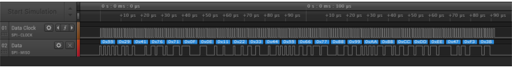
During transmission, the data clock and data is recorded on the respective GPIO pins:
Non-Triggered PER#
By default the application starts in packet mode with the receiver enabled. In this mode we receive and transmit packets using the radio's frame controller hardware. If a packet is received, the payload content and length, the RSSI, the CRC status, and the time can be read from the receiver response.
Example:
{{(rxPacket)}{len:16}{timeUs:290402914}{timePos:4}{crc:Pass}{rssi:-50}
{lqi:240}{phy:0}{isAck:False}{syncWordId:0}{antenna:0}{channelHopIdx:254}
{payload: 0x0f 0x0e 0x11 0x22 0x33 0x44 0x55 0x66 0x77 0x88 0x99 0xaa 0xbb
0xcc 0xdd 0xee }}This test also involves an RF signal generator, which can transmit predefined packets. In this mode, the radio is set to receive and the generator must send packets. If the radio does not receive the packet, there is no RX response. To view the number of received packets, CRC errors, and sync detect errors, use the status command.
Example:
{{(status)}{UserTxCount:38}{AckTxCount:0}{UserTxAborted:0}{AckTxAborted:0}{UserTxBlocked:0}
{AckTxBlocked:0}{UserTxUnderflow:0}{AckTxUnderflow:0}{RxCount:0}{SyncDetect:8}{NoRxBuffer:0}{RfSensed:0}
{ackTimeout:0}{ackTxFpSet:0}{ackTxFpFail:0}{ackTxFpAddrFail:0}{RfState:Rx}{RAIL_state_active:0}
{RAIL_state_rx:1}{RAIL_state_tx:0}{Channel:0}{AppMode:None}{TimingLost:0}{TimingDetect:0}{FrameErrors:8}
{RxFifoFull:0}{RxOverflow:0}{AddrFilt:0}{Aborted:0}{RxBeams:0}{DataRequests:0}{Calibrations:1}
{TxChannelBusy:0}{TxClear:0}{TxCca:0}{TxRetry:0}{UserTxStarted:38}}To reset all the counters use:
resetCounters Resets the Tx and Rx countersIf a long and fast test needs to be run, it is better to disable the Rx responses, to make the communication and the test faster.
setNotifications setRxNotification [enable] Enable(1) or Disable(0) status prints that happen asynchronously (rxPacket, txEnd, txError)Triggered PER#
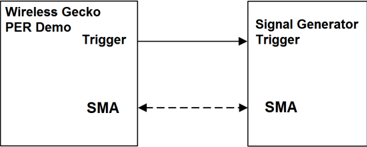
RAILtest can be used to determine the packet error rate (PER) for a given setup. The Wireless Gecko is capable of triggering a connected RF signal generator to transmit a specific number of packets with a configured trigger interval, counting the correctly received packets, and calculating the actual PER value.
To set up this test, a piece of test equipment needs to be configured to send a packet on the rising edge of a GPIO. That should be connected to PC7 on the EFR32, or PC3 on the WSTK. perRx 100 10000 will configure the Packet Error Rate test to send 100 packets, waiting 10000 μs between each packet. At the end of the test, the app will give an output indicating that PER mode has finished, and the statistics on the test can be recovered with perStatus and status. Note that calling perRx 0 0 will cancel an ongoing test, and that calling perRx will have the same effect as calling resetCounters.
By adjusting the output power of the generator, the sensitivity of the radio can be determined. It is usually defined for a 1% or 20% packet error rate.
BER Measurement#
Running Bit Error Test from the CLI#
The sensitivity of the radio can be measured with a continuously-looped PN sequence (x^9 + x^5 + 1). This mode is called bit error rate (BER). The EFR32 hardware has the ability to enter BER receive mode for diagnostic purposes. The radio is set into continuous receive mode. The RF data needs to be fed to the RX SMA of the test card or radio board. By adjusting the output power of the signal generator or an EFR32, the sensitivity of the radio can be measured (it is typically measured for 10^-3 BER). See RAILtest User's Guide for further information about BER testing mode.
BER Measurement Procedure#
To run the BER test successfully, a radio configuration specific to BER mode must be generated by the radio configurator. To enable BER testing mode by default on reset or startup:
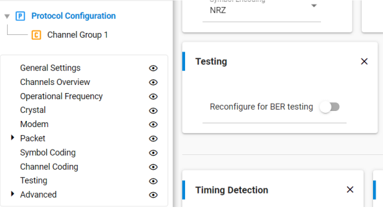
In Simplicity Studio 5 and 6:
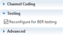
In the Radio Configurator, on the General Settings card enable Customized, and then on the Testing card enable Reconfigure for BER testing.
In Simplicity Studio 4:
Check Reconfigure for BER testing on the Radio Configuration tab.
Sensitivity Measurement#
Sensitivity of a device is the minimum level of received RF power that the device is capable of receiving. Sensitivity is often expressed in dBm. It is usually defined for a 1% or 20% packet error rate, which means that at the sensitivity level (in dBm) the receiver is capable to produce 1% or 20% PER. By adjusting the output power of the generator, the sensitivity of the radio can be determined.
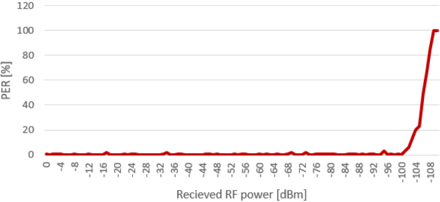
From this graph it can be determined that the sensitivity of a device at 20% PER is -104 dBm. In practice the sensitivity of a device depends on the radio configuration, such as modulation, deviance, and frequency.
To measure the sensitivity of a receiver, PER must be measured at various receiver power levels, in practice between 0 to -120 dBm values with 1 to 5 dB steps.
The measurement results are more accurate if the RF signal generators power steps finer and more packets are sent at each power step. In the above example, the PF power step is 1 dB and 100 packets were sent at each frequency step.
Other Receiver Measurements#
The measurement specifications may differ based on the standards for different regions, and are described in more detail in other documents.
Selectivity#
Selectivity is a measure of the capability of the receiver to operate correctly while an unwanted signal is present at an adjacent channel.
Measurement procedure: Two generators are used for this measurement. One is generating packets on the operating channel at the sensitivity level of the receiver +3 dB. The second generator is generating an unmodulated signal on the nearest adjacent channel. The maximum power of the second generator at which the RUT (Receiver Under Test) is not able to receive the packets of the first generator is the selectivity, expressed in dBm.
Blocking#
Blocking is a measure of the capability of the receiver to operate correctly while an unwanted signal is present at frequencies other than at an adjacent channel or spurious responses are.
Measurement procedure: Two generators are used for this measurement. One generates packets on the operating channel at the sensitivity level of the receiver +3dB. The other generates an unmodulated signal on a specified frequency offset, based on the local region's specification. The maximum power of the second generator at which the receiver under test is not able to receive the packets of the first generator is the blocking level, expressed in dBm.
Intermodulation#
The intermodulation response is a measure of the ability of the receiver to receive a wanted modulated signal, without exceeding a given degradation due to the presence of two or more unwanted signals with a specific frequency relationship to the wanted signal frequency.
Maximum Input Power#
Maximum input power is a measure of the maximum power at which the receiver is able to receive the packets without degradation of the signal quality.
RSSI Curve#
Received signal strength indicator (RSSI) is an estimate of the signal strength in the channel to which the receiver is tuned. The RSSI value can be read with 0.25 dB resolution per bit. The RSSI may be read at any time while the radio is in Receive mode. The RSSI is not latched, but continuously updated while in Receive mode.
To read the RSSI value, use the following command:
getRssi Get RSSI in dBm if the receiver is turned on.Example:
> getRssi
getRssi
{{(getRssi)}{rssi:-94}}
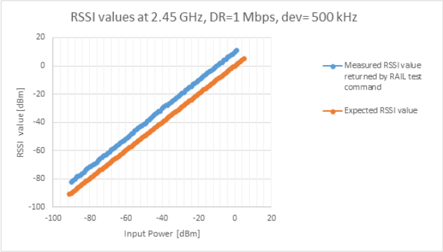
> >Note that a systematic offset (see figure below) will appear in the RSSI value returned by the RAILtest command due to matching network, radio configuration, and so on. You must profile the board and account for the offset when using the returned value.
Customer Production Test: Transmission Power#
The high resolution RSSI enables accurate channel power comparison measurement that can be useful for production tests transmission power without an instrument.
Measurement procedure:
Load the RAILtest application on two EFR32 nodes.
Set both nodes to the same channel with the
setchannel ncommand, where "n" is the channel number.Issue the
setTxTonecommand on the first node to set CW mode.Read the RSSI level on the second node with the
getRssicommand.