Setting up Range Test Applications on the Development Kits#
This section provides a quick summary on how to set up for range testing. Testing custom designs is outside the scope of this document. Therefore, the instructions assume the following:
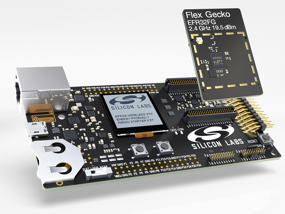
You have a complete development kit with two mainboards and two radio boards.
You have installed Simplicity Studio 5 and Flex SDK 3.x.
You are familiar with using Simplicity Studio to configure, build, and flash applications. For more details, see Proprietary Flex SDK v3.x Quick Start Guide or the online Simplicity Studio 5 User's Guide.
As noted above, running Range Test on a custom board is not extensively covered here. However, see section A Note On Modifying The Application For Custom Boards for some guidance on this subject.
Prepare the Wireless Starter Kits#
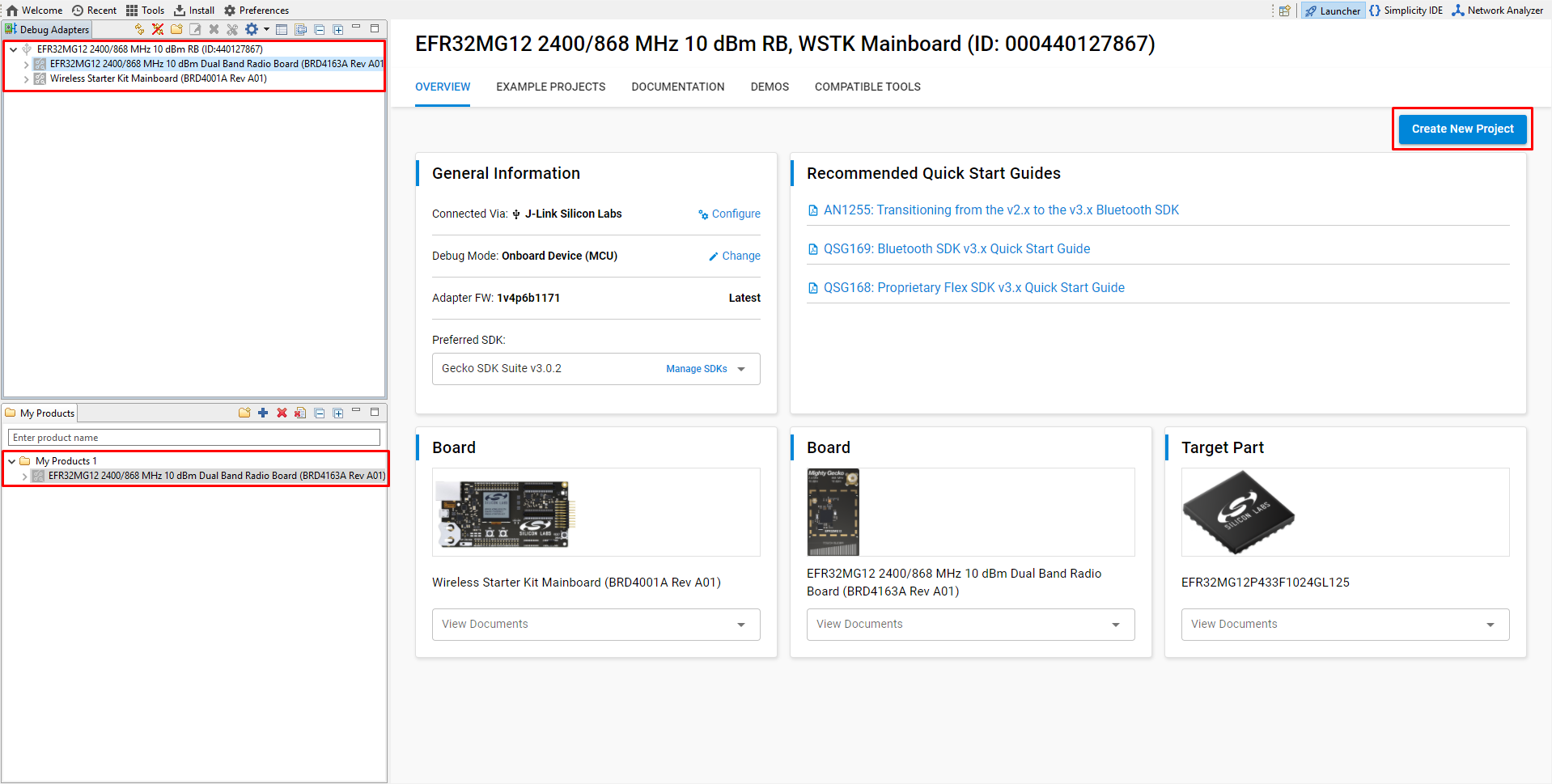
Every mainboard has a unique serial number that is displayed in Simplicity Studio's Launcher perspective once it is connected to the PC either with an ethernet or a USB cable.
The IP address and the serial number are displayed on the mainboard LCD during startup of the device, but may be lost when the app starts on the radio board. To see these again, disconnect and reconnect the mainboard’s power. Once the information is displayed, press and hold the RESET button. The information remains displayed as long as the button is pressed
Note: The mainboard should be powered through its USB port, even if it is connected via Ethernet. Also, make sure that the 3-position power switch in the bottom left is set to AEM as shown in the following figure.
If you are going to use the device as a mobile device to run the range test, connecting an external AA battery pack or a USB power bank to the mainboard board is recommended. The coin cell battery will not have enough power to do long-term testing. If the development kit is powered from a battery, change the 3-position switch from AEM to VBAT.
Create a New Range Test Application#
This section assumes that you have installed Simplicity Studio 5 and the Flex SDK, and have your device(s) connected to the PC.
Note: If you do not have a physical device handy, select the corresponding part in the My Products view to create a "virtual" device.
Select the physical or virtual device so that the OVERVIEW and other tabs are displayed in the Launcher perspective.
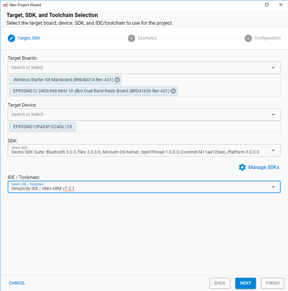
Alternatively, you can generate a project without a virtual or physical device by selecting Project > New > Silicon Labs Project wizard. Select the target board and the preferred SDK along with the toolchain, and click [Next].
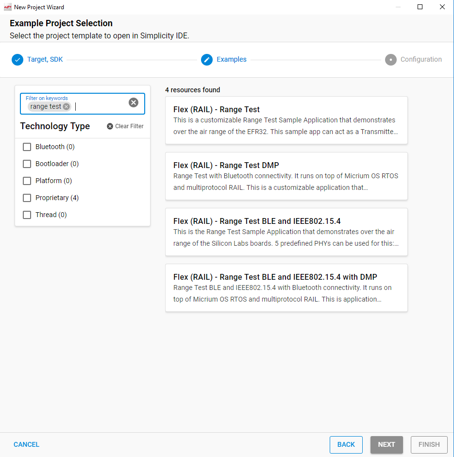
In the Example Project Selection dialog, you can browse through the supported applications for the given part. You may filter with the Range Test keyword. Select an application and click [Next].
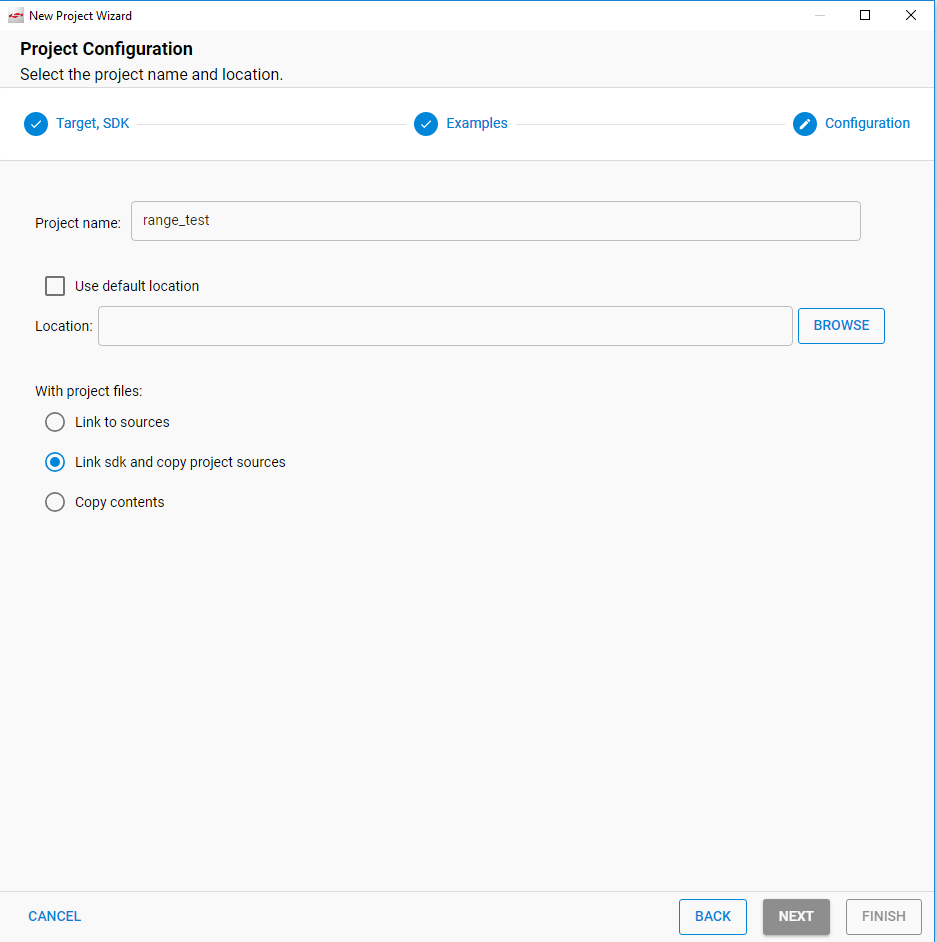
Rename the project, if desired. The project is placed into your current workspace by default, but you can select a different location. Finally, either copy the sources or link to them. Click [Finish]. Project creation may take a short time.
Note: Creating the project means copying or linking all the required source code into your project's folder, setting up project configurations based on the installed components and generating all the project customizations (basically through header files) according to the configurable components' default settings.
Customizing the Application#
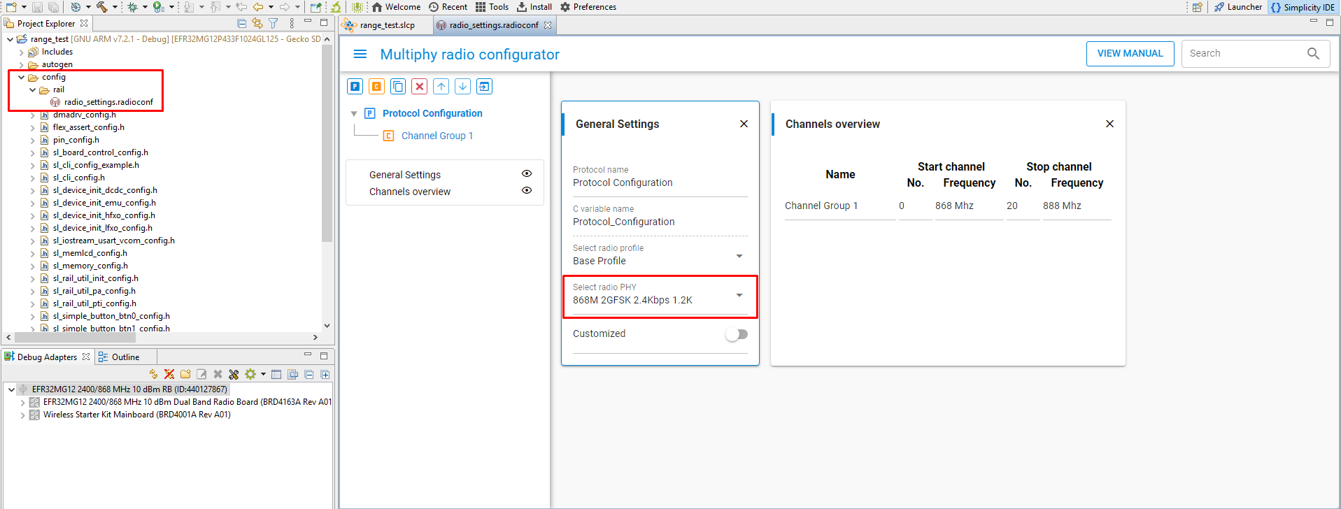
If you have created a custom PHY application, the Radio Configurator interface (stored in the .radioconf file) is displayed. Here you can set up the desired PHY. You can browse through the built-in PHYs or create a custom configuration (recommended only for experienced users). Saving this file generates a new radio_config.c file. For more information on how to set the modem parameters, refer to Proprietary Radio Configurator Guide.
Otherwise, for a Standard PHY application, the project's, the .slcp file is opened in the project editor tool called the Project Configurator. Generally, and if you are working with development kits, you should not modify this file. The project is ready to build.
Note: If you closed the Radio Configurator, you can re-open it from the Project Configurator’s Configuration Tools tab.
A Note on Modifying the Application for Custom Boards#
Though the default Range Test user interface is the mainboard's LCD and push buttons, the application can be driven exclusively by CLI if desired. Hence, with some modifications, Range Test applications can run on custom designs that lack LCD and push buttons.
The standard single protocol version of Range Test simplifies this task, reducing the effort required to purge LCD and push button support from the application to two simple steps. In the Component Editor, uninstall the following components (search for the component name to locate):
Simple Button
GLIB Graphics Library
Doing so removes all dependencies but retains the Sleeptimer component. Macros in the application source code will then exclude from the build sections related to the LCD and push buttons, enabling the project to compile with only CLI support. Porting this to a custom board may require further modifications to translate the mainboard default settings (for example, the USART configuration) to the custom design, but the steps above will produce a viable CLI-only application that can be demonstrated on a mainboard before transitioning to your custom target.
PHY Limitations#
Range Test applications work with a fixed packet length by default. Some profiles (Long Range, Connect, wM-Bus) define variable length packet configurations in their PHYs, but length configuration will be overridden with the fixed length setup configured on the application's menu. This limitation should be considered when designing the protocol for evaluation.
Build the Application#
When you have finished configuring the project, click Build (hammer icon) on the toolbar.
![]()
![]()
Your sample application will be compiled based on its build configuration.
Load the Application onto a Device#
Once the binary file has been generated you can flash it onto a connected device with the following options:
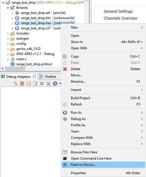
Use Flash to Device: Right-click the image file in Project Explorer view and select Flash to Device to open the Flash Programmer.
Use Simplicity Commander: Run the executable file located under Simplicity Studio's installation folder in the
developer/adapter_packs/commanderfolder, or open it through the Tools button on the toolbar or the Project COMPATIBLE TOOLS tab.Use the debug functionality: Click Debug (bug icon) on the menu to (incrementally) build the project if any modifications have been made since the last build. With this mode all the debug functionality will be available.