Using the Range Test Applications#
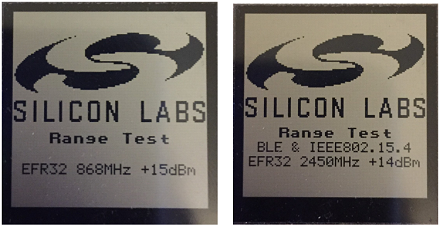
On startup, the Welcome Screen is shown on the LCD. This includes the Silicon Laboratories logo, the carrier frequency and the RF power level. The Welcome Screen is shown for up to three seconds, or as long as any push button is held down. The following figures show the Welcome screen for Custom PHY applications and Standard PHY applications, respectively.
Configuration#
Configurable Parameters#
Next, the LCD displays the menu, on which the (mostly configurable) parameters and functions are displayed. The menu differs slightly, depending on the selected mode. The Show Information and the Start Range Test functions are also displayed. Selecting Show Information refreshes the screen to show the Welcome Screen again. The following figures show the menu for TX and RX.
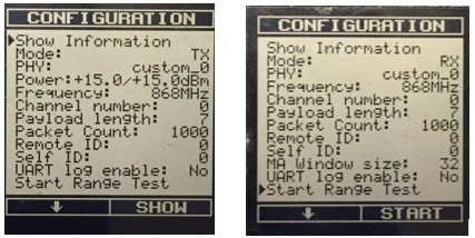
The menu options are:
Common#
Mode (RX or TX): The applications start in RX mode by default, but the mode can be changed any time, before or between measurements. In addition, the same device can act as a transmitter and then as a receiver without resetting the device.
PHY: Only configurable in a Standard PHY application (BLE 1/2Mbps or 802.15.4) and if you have a Multi-PHY radio configuration in a Custom PHY application.
Frequency: Not a configurable parameter, but shows the selected PHY's base channel frequency. Therefore it is not updated when the Channel number is increased.
Channel number: Selects the channel on which the RX node(s) will listen or the TX node will transmit.
Payload length: Configurable between 7-64 in a Custom PHY application. In a Standard PHY application it can be configured to between 5-24 with a BLE PHY or 5-116 with an 802.15.4 PHY.
Packet count: Ranges from 500 to infinite in both Modes, and sets the transmitted/expected number of packets on the participants.
Remote/Self ID: In RX Mode, the radio listens on the given channel and inspects the packets received. Only packets that are sent with matching Self ID and Remote ID will be processed. Therefore the IDs should be configured on the TX accordingly.
RX/TX only Parameters#
MA Window size (RX only): Moving Average or MA window size configures how many packets will be counted in a shorter PER measurement during the test. The moving average PER is useful when trying to position the devices until you get a specific PER, for example to find the maximum distance between the units for 1% PER. The moving average in this case shows an almost instantaneous PER. When the positions are fixed you can re-run the test and the total PER for many packets will provide more accurate result.
Power (TX only): Output power can be set in the LCD menu in 0.5 dBm steps (power setpoint), between -15 and +20 dBm. Actual minimum and maximum power may vary on different frequencies and different parts. Also, the target power may differ from the power that is set by RAIL. The LCD menu informs the user about the setpoint and the actual power in that order.
UART log enable (TX only): If on, a status message can be observed on the UART TX line for each radio packet, formatted in human readable format. The default pin assignment is the standard VCOM port available on the mainboard.
Note: This mode will not interfere with the command line interface (CLI). The CLI will be available regardless of whether or not the UART log is enabled.
Many of these options are also available in the EFR Connect smartphone app. After the menu items are configured, the range test can be started. During the test, all of the measured information can be observed on the LCD or the smartphone's screen.
Configure on the LCD Menu Using Push Buttons
The two push buttons on the mainboard are used to navigate through the menu system; soft labels on the bottom of the screen describe the current function of each button. In general, button 1 is used to navigate down through the menu items. Button 0 is used to configure the menu item selected by the pointer. Items with a + sign in the right bottom label are configurable.
Configure Using the Command Line#
You can access all the configurable parameters (not depending on the Mode) through the CLI. The parameters can be written or read by commands starting with set or get, respectively.
To see the available commands and the available arguments issue, the help command.
Configure Through the EFR Connect Smartphone Application#
Many configurable parameters can be set through the EFR Connect smartphone application, once a connection has been established. See section Configurable Parameters for more information
Using the EFR Connect Smartphone Application#
The Silicon Labs EFR Connect app uses the Bluetooth adapter on your phone/tablet to scan, advertise, connect, and interact with Bluetooth LE devices.
Documentation for EFR Connect is available through docs.silabs.com. When the EFR Connect smartphone app is opened, the following screen is displayed.
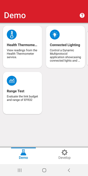
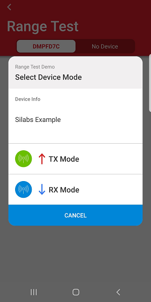
Select Range Test Demo from the list of available applications.
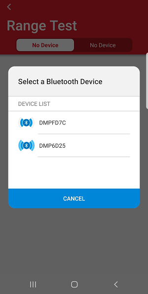
Select the kit to which you would like to connect. The IDs are the last 4 bytes by of the MCU's Unique ID.
Select the application's mode: TX or RX.
Selecting a mode establish the connection, and the device stops advertising as long as it is connected to the smartphone. Therefore you should reconnect to the device to change its mode.
Note: An ongoing RX measurement will block re-connection, since the device will not advertise while it is waiting for the TX node's packets. To reconnect, first terminate measurement either by using the push buttons or by a CLI command.
The following figures show the starting screen for RX and TX.
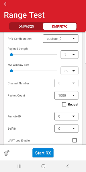
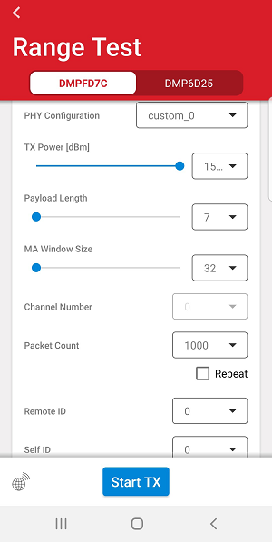
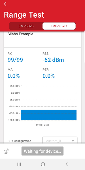
The following screens shows RX and TX mode with ongoing measurements.
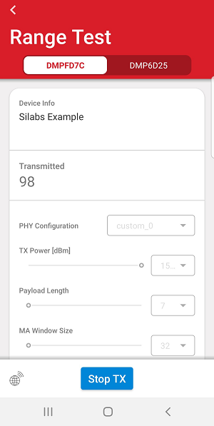
The same configuration parameters are available as on the LCD.
Notes:
Do not change the Mode using the push buttons or a CLI command while the connection is established between the device and your smartphone.
If you measure Bluetooth LE PHY in a Standard PHY application, the connection will be created through a separate Bluetooth LE protocol, with the Bluetooth LE stack, and will not interfere with the measurement.
If you start an RX measurement, stop it before trying to reconnect to the device. Otherwise the device will not advertise itself. However, during TX measurement the device continues to send advertising packets.
The smartphone application has a much longer RSSI history than is available on the mainboard's LCD.
Application Execution Tips#
The test on the TX side runs as long as the number of transmitted packets reaches the predefined number or until the test is terminated by pressing Button 0. You can follow the number of transmitted packets on the transmit-side's LCD.
The RX side restarts whenever it receives a lower-indexed packet than the last one with the expected Remote and Self ID. The signal strength of the incoming packet is measured during packet reception, and the actual RSSI value is shown on the LCD. The RSSI values are also presented as a graph.
The number of lost packets and the packet error rate are defined only at the receive side and are based on the first and last received packet numbers, regardless of the Packet count parameter.
The RSSI is typically used to qualify the link: a higher level might show a better link quality. The actual RSSI value is measured when the sync word of the packet is received (for more details see RAIL_RxPacketDetails_t.rssi).
It is not necessary to start both sides synchronously as well as to receive the first N packets.
The range test can be performed inside a building if indoor propagation is tested. However, line-of-sight testing outside the building is recommended to get the best possible range result, as well as the best comparable results from different settings. It is also recommended that the antennas be located at least 1.5 m above the ground.
If PER < 1%, reset the current measurements on the boards and try moving the two devices closer. Propagation conditions usually improve if you distance yourself from a possibly faded area.