About Antenna Diversity#
An EFR32 can select between two antennas (referred to as ANT0 and ANT1) for packet transmission and for packet reception, to mitigate the effect of fading due to multipath propagation experienced particularly in indoor environments. Rx and Tx antenna selection are independent of each other. Tx selection is handled completely on the application side where a manual override for Rx selection is also possible.
Indoor fading typically causes 5-6 dB reduction in received signal strength. In practice this means that if one antenna falls into a “dead spot”, resulting in bad or no reception, switching to the other one can result in an improved link performance assuming correct antenna placement. Fading conditions vary over time due to moving objects and people, therefore a dynamic and agile antenna validation and selection feature is needed.
The Antenna Diversity feature facilitates two kinds of automatic methods for Rx antenna selection on top of the manual one, namely the Select-First-Good (SFG) and the Select-Best (SB) algorithms. Only SB takes into account signal quality for antenna selection, where signal/antenna quality is based on RSSI measurements.
When antenna diversity is enabled, the radio keeps toggling in Rx between the two antennas until timing detect occurs on one of them. For more information, see Timing Detection. Only the switching pattern and selection strategy differs for the two main modes, SFG and SB.
Note: The radio reverts back to SFG whenever the input signal level is perceived by the AGC block to be high enough for proper detection. This is typically between -65 to -80 dBm, well above sensitivity levels. When low signal levels are reached, antenna diversity will switch its operation mode back to the requested and preferred one automatically.
For deterministic operation, after every antenna switching not only the timing detection but the AGC block plus DC and frequency compensation are also restarted. Therefore a proper antenna dwell time, and thus the preamble length, will be a main factor in using antenna diversity effectively. The latter is critical in giving enough time to complete the detection and selection process before the sync word arrival, in every possible situation. Different modes require different amount of preamble time for their proper operation.
The required preamble length is dependent on:
Length of the timing sequence used for Timing Detection
AGC and detection block settle times at antenna switching
Internal processing time
RSSI measurement time
At any point during or after the selection process, when timing is lost, antenna switch will occur and the operation restarts, in other words the radio goes back to timing search.
The antenna dwell time is automatically determined by the configured timing detection scheme, AGC and RSSI measurement settings, and highly correlates with the timing window length.
Note: The internal base profile PHYs were created without antenna diversity in mind. Thus at least the timing detection scheme (number of symbols in timing window, number of timing windows to detect, timing samples threshold), preamble length, AGC settling delay, and RSSI measurement settings must be reviewed under the Advanced tab of the radio configurator when enabling antenna diversity. Since the driving event behind antenna diversity is timing detection, a robust yet fast timing detection scheme is required to save preamble time in general and to avoid false timing detects triggering unnecessary antenna selection process resulting in possible packet miss.
Note: Due to the short antenna dwell times Automatic Frequency Cancellation feature is not available, only the Internal Frequency Compensation can be used.
After timing detection is asserted on one antenna the algorithm can follow various paths based on the configuration in Antenna Diversity Mode.
Antenna switching can be internal or external. In case of external diversity, a GPIO-controlled external switch is used to toggle between the antennas. Conversely, internal switching is done by toggling internal RF paths that are connected to the antennas. Both of these modes utilize hardware to determine the best source option.
Note: Internal antenna diversity is only available on Series 2 devices: xG21 and xG23. For xG28, this feature is applicable only to certain parts, where each RF path goes to a different antenna.
Antenna Diversity Application Support#
The various Silicon Labs software stacks and SDKs such as EmberZNet, Silicon Labs Thread, and Flex support antenna diversity on different levels and with different feature lists. For those implementations please consult the corresponding documentation regarding antenna diversity feature support, for example AN1181: Configuring Antenna Diversity for EmberZNet.
Custom and/or stackless implementations should rely on the RAIL API in using antenna diversity. We give a quick summary here, but for specifics please search the RAIL documentation available here: https://docs.silabs.com.
To use antenna diversity with RAIL, the sl_rail_config_antenna() API can be
used to configure the GPIO pins that will drive the external RF switch. In case
of internal RF path switching, the default_rf_path field of
sl_rail_antenna_config_t should be set to SL_RAIL_ANTENNA_AUTO'.
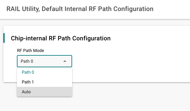
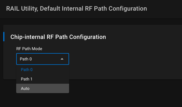
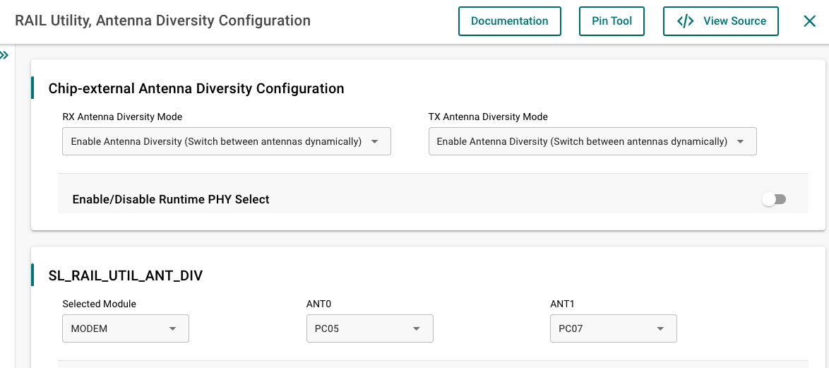
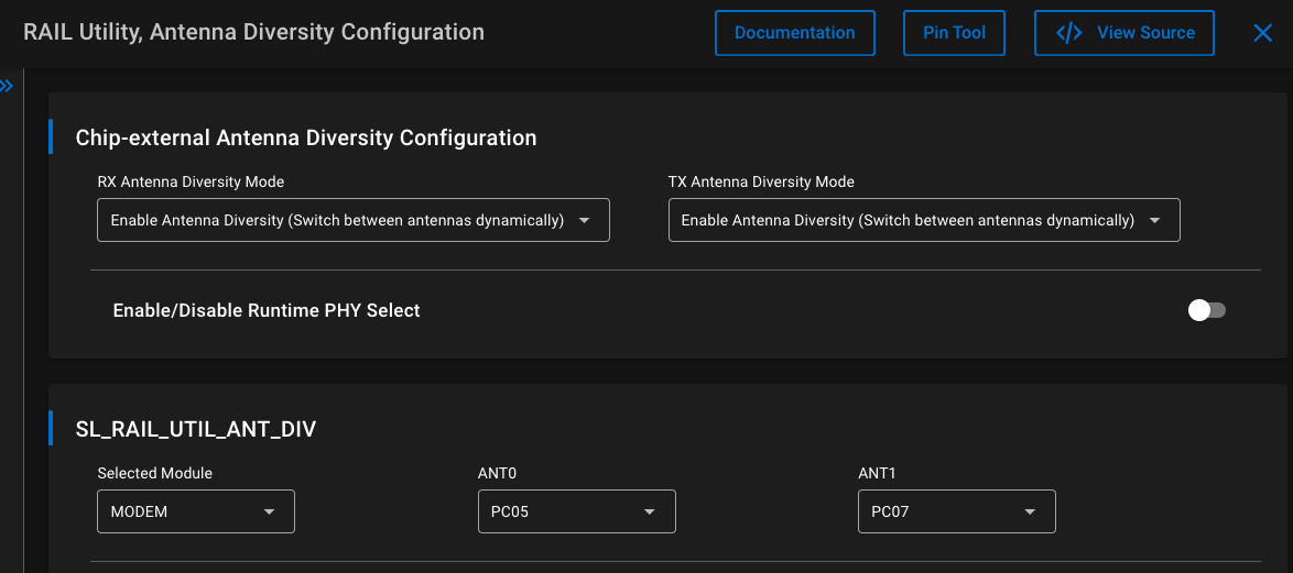
As shown in the images below, antenna diversity can be also configured from Software Components. Use RAIL Utility, Default Internal RF Path Configuration with RF Path Mode set to Auto for the internal one and RAIL Utility, Antenna Diversity Configuration for configuring the external switch.
The Rx behavior of the radio can be configured with
sl_rail_config_rx_options() passing either SL_RAIL_RX_OPTION_ANTENNA_0,
SL_RAIL_RX_OPTION_ANTENNA_1 for static, manual antenna selection (meaning Rx
diversity off); or SL_RAIL_RX_OPTION_ANTENNA_AUTO for dynamic, automatic
selection as an argument (meaning Rx diversity on). The antenna_id field of
sl_rail_rx_packet_details_t indicates on which antenna was the packet
received.
The algorithm of Rx antenna diversity itself, when enabled, is governed by the configuration in the Radio Configurator's Antenna card (Advanced group).
The antenna selection for a Tx operation is handled at the Tx starting API functions like sl_rail_start_tx() and similar by passing options SL_RAIL_RX_OPTION_ANTENNA_0 or SL_RAIL_RX_OPTION_ANTENNA_1. If neither or both of these option is set at the function call then Tx takes place on the antenna defined/determined by the last Rx or Tx operation. So, by default (not passing an antenna-related Tx option) all Tx operation takes place on the antenna where the last packet was received by antenna diversity.
The Auto-ACK message is transmitted on the antenna where the ACK-ed frame in question was received by antenna diversity.