Using the Radio Configurator#
For Wireless M-Bus configurations, always use the Mbus Profile:
Multi-PHY Configuration#
The following modes require multiple PHYs:
Mode T2 (bidirectional only)
Mode C2 (bidirectional only)
Mode N has a separate PHY for each bitrate (index 1-5-7-10; 2-6-8-11; 4-18 and 3-9-13). In the 2013 release of EN13757-4, the naming was different. See the tables in Recommended Configurations below.
Modes C, N, and F have separate PHYs for frame formats A and B
The Radio Configurator can be used to set up virtual channels. For example, channel 0 can be used for Mode T meter to other and channel 1 can be used for Mode T other to meter.
There are other possible uses, such as supporting all 868MHz based modes (S, T and C) with simple channel changes.
It is also possible to configure an application with multiple protocols as Wireless M-Bus modes. In order to change protocols RAIL_ConfigChannels must be used. This can be useful to select a mode during boot or configuration. For further details, if you are working with Proprietary Flex SDK v2.x see AN971: EFR32 Radio Configurator Guide for RAIL in Simplicity Studio v4. If you are working with Flex SDK v3.x see Proprietary Radio Configurator Guide.
The Wireless M-bus Meter example application is configured to support Mode T2 bidirectional mode using Multi-PHY configuration.
Recommended Configurations#
For 868 MHz and 434 MHz bands#
Mode | Submode | Single PHY Configuration Name (frame A) (1) | Single PHY Configuration Name (frame B) (1) | Freq. (MHz) |
|---|---|---|---|---|
Mode S | N/A | WMbus S (32.768k, Manchester) | 868.3 | |
Mode T | Meter to Other, Rx | WMbus T M2O (100k, 3of6) (2) WMbus T M2O, no postamble (100k, 3of6) (3) | 868.95 | |
Meter to Other, Tx | WMbus T M2O (100k, 3of6) (2) WMbus T M2O (100k, no framing) (4) | 868.95 | ||
Other to Meter | WMbus T O2M (32.768k, Manchester) | 868.3 | ||
Mode TC | Meter to Other | WMbus TC M2O (100k, frameA) (2) (5) | 868.95 | |
Mode R2 | N/A | WMbus R2 (4.8k, Manchester) | 868.33 | |
Mode C | Meter to Other | WMbus C M2O frameA (100k) (6) | WMbus C M2O frameB (100k) (7) | 868.95 |
Other to Meter | WMbus C O2M frameA (50k) (6) | WMbus C O2M frameB (50k) (7) | 869.525 | |
Mode F | N/A | WMbus F, frameA (2.4k) (6) | WMbus F, frameB (2.4k) (7) | 433.82 |
Notes:
The names were changed from earlier releases to make them more uniform, but they always included the mode, the bitrate, and the frame type (where applicable)
Only for EFR32 series 2 with Wireless M-Bus support.
Only for EFR32 series 1. Could also work in Tx mode, but it does not generate the postamble required by the standard.
Only for EFR32 series 1. Should be used with the supplied software encoder (
WMBUS_phy_software()function).See Decoder for Both C and T Mode Meter to Other for details.
Sync word for frame format A is set up for sync word 0, sync word for frame format B is set up as sync word 1 but is not enabled by default. Receiving frame format B is not possible, but the sync detect event could be used.
Sync word for frame format B is set up for sync word 0, sync word for frame format A is set up as sync word 1 but is not enabled by default. Receiving frame format A is not possible, but the sync detect event could be used.
For the 169 MHz band (Mode N)#
Index (according to EN13757-4-2019) | Single PHY configuration (Frame A) (1,2) | Single PHY configuration (Frame B) (1,3) | Freq. (MHz) | Channel Spacing (kHz) | Last channel number |
|---|---|---|---|---|---|
1 (4) | WMbus N, index 1/5/7/10, frameA (2.4k) | WMbus N, index 1/5/7/10, frameB (2.4k) | 169.40625 | 12.5 | 5 |
2 (5) | WMbus N, index 2/6/8/11, frameA (4.8k) | WMbus N, index 2/6/8/11, frameB (4.8k) | 169.40625 | 12.5 | 5 |
3 (7) | WMbus N, index 3/9/12, frameA (6.4k) | WMbus N, index 3/9/12, frameB (6.4k) | 169.41 | 12.5 | 5 |
4 (6) | WMbus N, index 4/13, frameA (19.2k) | WMbus N, index 4/13, frameB (19.2k) | 169.4375 | 50 | 0 |
5 | WMbus N, index 1/5/7/10, frameA (2.4k) | WMbus N, index 1/5/7/10, frameB (2.4k) | 169.48125 | 12.5 | 0 |
6 | WMbus N, index 2/6/8/11, frameA (4.8k) | WMbus N, index 2/6/8/11, frameB (4.8k) | 169.48125 | 12.5 | 0 |
7 | WMbus N, index 1/5/7/10, frameA (2.4k) | WMbus N, index 1/5/7/10, frameB (2.4k) | 169.49375 | 12.5 | 7 |
8 | WMbus N, index 2/6/8/11, frameA (4.8k) | WMbus N, index 2/6/8/11, frameB (4.8k) | 169.49375 | 12.5 | 7 |
9 | WMbus N, index 3/9/12, frameA (6.4k) | WMbus N, index 3/9/12, frameB (6.4k) | 169.41 | 12.5 | 57 |
10 | WMbus N, index 1/5/7/10, frameA (2.4k) | WMbus N, index 1/5/7/10, frameB (2.4k) | 169.59375 | 12.5 | 17 |
11 | WMbus N, index 2/6/8/11, frameA (4.8k) | WMbus N, index 2/6/8/11, frameB (4.8k) | 169.59375 | 12.5 | 17 |
13 | WMbus N, index 4/13, frameA (19.2k) | WMbus N, index 4/13, frameB (19.2k) | 169.625 | 50 | 3 |
Notes:
The names were changed from earlier releases to make them more uniform, but they always included the mode, the bitrate, and the frame type (where applicable)
Sync word for frame format A is set up for sync word 0, sync word for frame format B is set up as sync word 1 but is not enabled by default. Receiving frame format B is not possible, but the sync detect event could be used.
Sync word for frame format B is set up for sync word 0, sync word for frame format A is set up as sync word 1 but is not enabled by default. Receiving frame format A is not possible, but the sync detect event could be used.
Submodes, according to EN13757-4-2013, available on this index: N1c, N2c (on ch1); N1d, N2d (on ch3).
Submodes, according to EN13757-4-2013, available on this index: N1a, N2a (on ch0); N1b, N2b (on ch1); N1e, N2e (on ch4); N1f, N2f (on ch5).
Same as submode N2g in EN13757-4-2013.
Only available on EFR32 Series 2 with Wireless M-Bus support.
Using Custom Settings#
All the above configurations (and more) can be set up using Custom settings. Currently, to use the multi-PHY features, you have to use custom settings for all but the first (virtual) channel.
For details about the Wireless M-Bus custom setting parameters, see Proprietary Radio Configurator Guide.
Using Multi-PHY Features#
The following procedure shows how to set up a T2 meter/collector on Series 2 as an example, using Simplicity Studio 5 and Flex SDK v3.x. The settings to use are the same as in earlier configurator versions, but the Multi-PHY configurator workflow changed significantly between Simplicity Studio 4 and Simplicity Studio 5. To apply these changes in Simplicity Studio 4, see AN971: EFR32 Radio Configurator Guide for RAIL in Simplicity Studio v4.
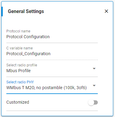
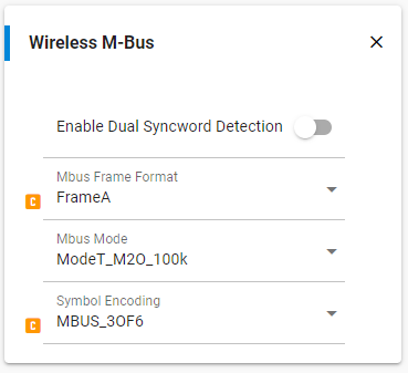
First, select the PHY you wish to use as channel 0 under the protocol setup. In the example, this would be M2O TRx setup, which is WMbus T M2O (100k, 3 of 6).
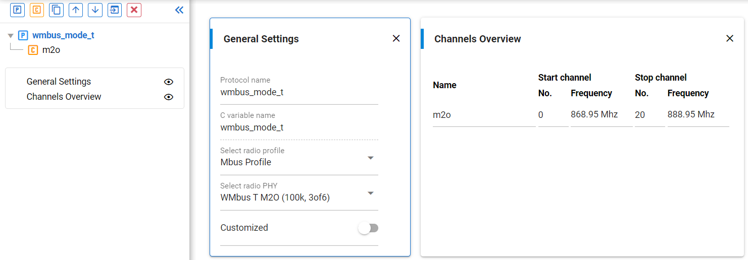
With this, the default channel group is already set for Mode T M2O. All that remains is to set the channel numbering and the name.
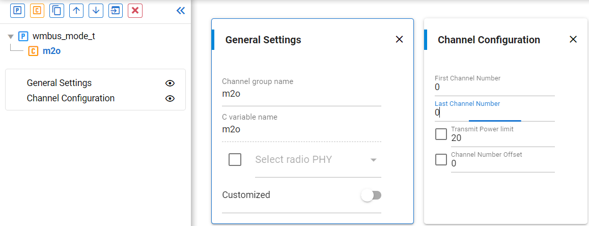
Create a new channel group by clicking the [C] control on the menu in the upper left and select the O2M TRx setup, which is WMbus T O2M (32.768k, Manchester). Set the channel numbering so that channel 1 will correspond to this PHY.
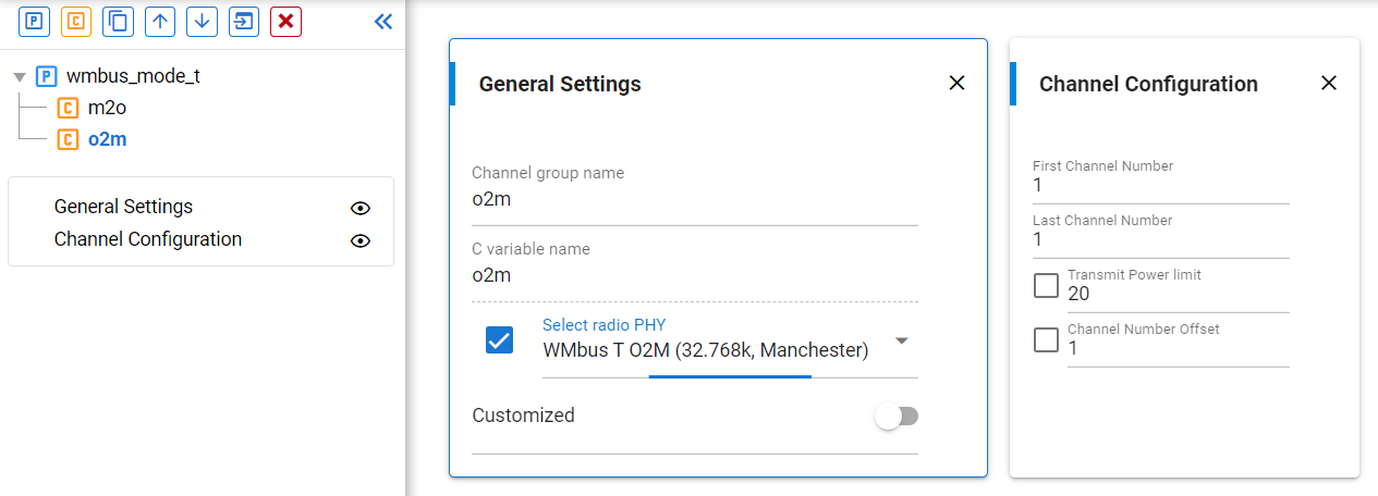
With this setup, a meter can transmit on channel 0 and receive on channel 1, while a collector can transmit on channel 1 and receive on channel 0.