Example Application#
The provided example application pair implements a very basic meter-collector interaction.
Meter#
Note: In Flex SDK 2.x, both TX_CHANNEL and the mode variable can be found in main.c.
The meter periodically sends synchronous SND-NR messages with some hardcoded value with mode 5 security. While waiting, it sleeps in EM2 in idle or EM1 if the main oscillator is required for scheduling or Rx mode. By default, the meter is configured for limited access mode (short receive window after transmission), but it doesn’t handle any received packets, it is just implemented to demonstrate the scheduling required for an application.
The application will always transmit on the channel defined by TX_CHANNEL in app_init.h (0 by default). In symmetric modes (S, R2, N, F), TX_CHANNEL is also used for reception. In asymmetric modes (T and C), TX_CHANNEL+1 is used for reception.
In Flex SDK 3.x, be sure to select the correct mode in the wireless M-bus support component configuration, as described in The Wireless M-Bus Support Component. In Flex SDK 2.x, the same configuration should be applied in the main.c file:
static const WMBUS_Mode_t mode = WMBUS_MODE_T_METERThe meter application also includes wmbus_sample_frame.c and .h, which can be used for guidance on how to assemble a simple wmbus frame.
Meter Peripherals#
The meter example, depending on the devkit it is running on, implements various sensors:
Virtual water meter sensor, which periodically increments.
Pulse counter, which increments on button press of BTN0. In the M-Bus frame, this is transmitted as energy in watt-hours (Wh).
Thermometer, which uses the on-board Si7021 to get temperature measurements.
The latter two are only available on development kits which have the required peripheral.
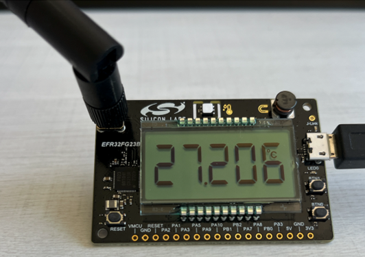
On FG23-DK2600, the 5-digit 7-segment LCD shows the measurement of one of the sensors. The active sensor can be selected by pressing BTN1.
The meter device enters EM2 sleep when in idle. It provides a command line interface on serial port at 9600 baud, to allow it to work in EM2 sleep. On the command line interface, the active sensor can be selected.
Collector#
The collector prints the received packet on serial terminal, with some information (like the first block) detailed. If the packet is EN13757-3 compatible with the short header, it also decodes mode5 security, if required.
Once the meter and collector are running, the collector should print messages like this to the serial terminal:
RX:[Time:163580960]
Block-1:[L:30,C:0x44,M:SIL,ID:00000001,Version:0x01,devType:0x07]
AppHeader:[CI:0x7A,AccessNr:60,Status:0x00,encMode:5,Accessibility:02,encBlocks:1,sync:1]
[0x2F 0x2F 0x04 0x13 0x39 0x30 0x00 0x00 | 0x02 0x3B 0x7B 0x00 0x2F 0x2F 0x2F 0x2F]A Wireless M-Bus sniffer can also be used. In that case, the default crypto key used by the application is:
00112233445566778899AABBCCDDEEFF.
For unencrypted packets, RAILTest also can be used as a sniffer with the right meter to another device to receive configuration.