Bootloader#
This section briefs about features supported by the Network and Security Processor's (NWP) bootloader.
Basic Features#
Load default firmware
Load selected firmware
Update firmware from the host
Selecting default images
Enable / Disable host interaction bypass
Support for multiple host interfaces (SDIO/SPI/UART/USB-CDC)
Firmware integrity check
Upgrading keys
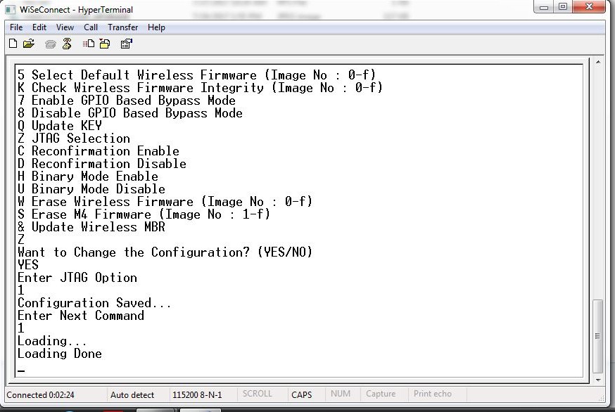
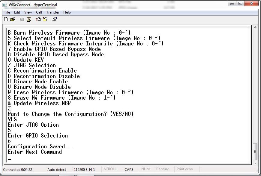
JTAG selection
The RS9116W supports two boot loading modes. They are:
Host interaction (Non-bypass) Mode. In this mode, the host can interact with the bootloader and can give boot up options (commands) to configure different bootup operations. The host tells the module what operations it has to perform based on the selections made by the user.
Bypass mode. In this mode, bootloader interactions are completely bypassed and uses the stored bootup configurations (which are selected in host interaction mode) & loads default firmware image in the module. This mode is recommended for final production of software to minimize the bootup time.
Host Interaction Mode#
In this mode host interaction varies based on host interface. Host interaction in SPI and UART / USB-CDC are different. In UART & USB-CDC boot up options are menu based and in SPI using command exchanges. The details are explained below for UART and USB-CDC.
Host Interaction Mode in UART / USB-CDC#
This section explains the host interaction mode in the UART / USB-CDC mode.
Startup Operation#
After powering up, host is required to carry out ABRD (Auto baud rate detection) operation. After successful ABRD, the module displays the menu of bootup options to host. The host needs to select the appropriate option.
Note!
On powerup, the bootloader checks the integrity of the bootup options. If the integrity fails, it computes the integrity from backup. If integrity passes, it copies the backup to the actual location. If the integrity of the backup options also fails, the bootup options are reset/cleared. In either of the cases, bootloader bypass is disabled, or corresponding error messages are given to host. In case of integrity failure and when the backup integrity check passes, "LAST CONFIGURATION NOT SAVED" message is displayed. When backup integrity also fails, "BOOTUP OPTIONS CHECKSUM FAILED" is displayed before displaying the bootup options.
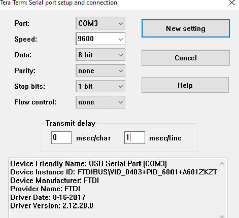
Terminal Configuration#
RS9116W uses the following UART interface configuration for communication via a terminal application such as TeraTerm, PuTTY or Hyperterminal:
Parameter | Setting |
|---|---|
Baud rates |
|
Data bits |
|
Parity |
|
Stop bits |
|
Flow control |
|
Note!
Default baud rate of the module is 115200.
Before the module is powered up, follow the sequence of steps given below:
Open the terminal and enter any name in the "Name" field. After this, click "OK" button. Here, "WiSeConnect" is entered as shown in the figure below.
After clicking "OK", the following dialog box is displayed as shown in the figure below.
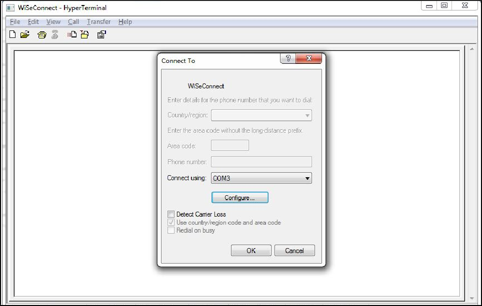
In the "Connect using" field, select appropriate com port. In the figure above COM3 is selected. Click "OK" button.
After clicking the "OK" button the following dialog box is displayed as shown in the figure below.
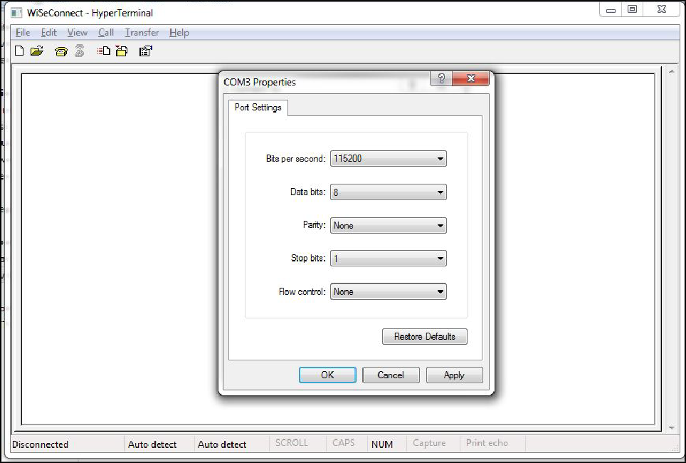
Set the following values for different fields in figure 5 as given below.
Set baud rate to 115200 in "Bits per second" field.
Set Data bits to 8 in "Data bits" field.
Set Parity to None in "Parity" field.
Set stop bits to 1 in "Stop bits" field.
Set flow control to None in "Flow control" field.
Click "OK" button after entering the data in all the fields.
Auto Baud Rate Detection (ABRD)#
The RS9116W automatically detects the baud rate of the Host's UART interface by exchanging some bytes. The Host should configure the UART interface for the following parameters for ABRD detection. To perform ABRD on the RS9116W, the host must follow the procedure outlined below.
Configure the UART interface of the Host at desired baud rate.
Power on the RS9116W.
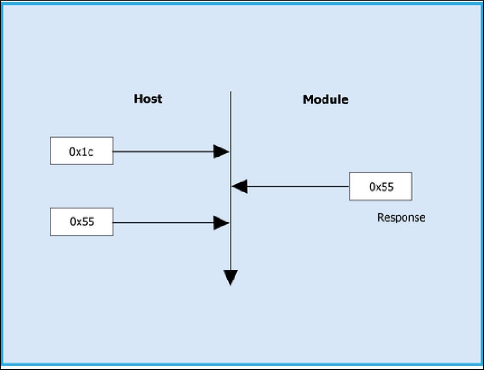
The Host, after releasing the module from reset, should wait for 20 ms for initial boot-up of the module to complete and then transmit 0x1C at the baud rate to which its UART interface is configured. After transmitting '0x1C' to the module, the Host should wait for the module to transmit 0x55 at the same baud rate.
If the '0x55' response is not received from the module, the host has to re-transmit 0x1C, after a delay of 200ms.
After finally receiving '0x55', the host should transmit '0x55' to the module. The module is now configured with the intended baud rate.
Note!
Performing ABRD in host interaction mode is must for USB CDC and UART mode.
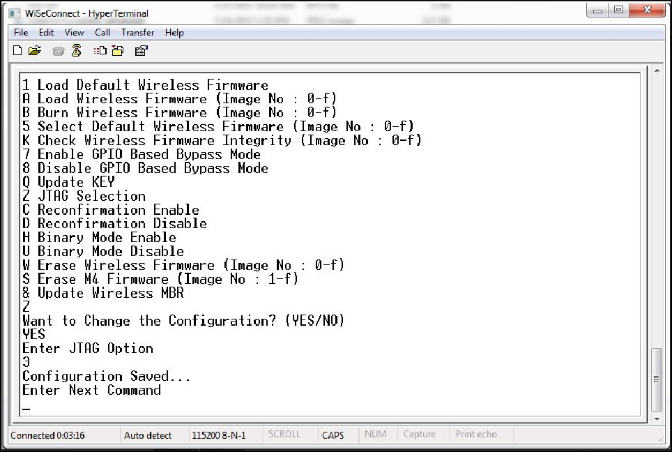
Below are the bootup options, Firmware update and Firmware loading procedures for WiSeConnect Product.
Start-Up Messages on Power-Up#
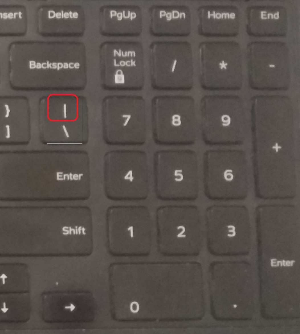
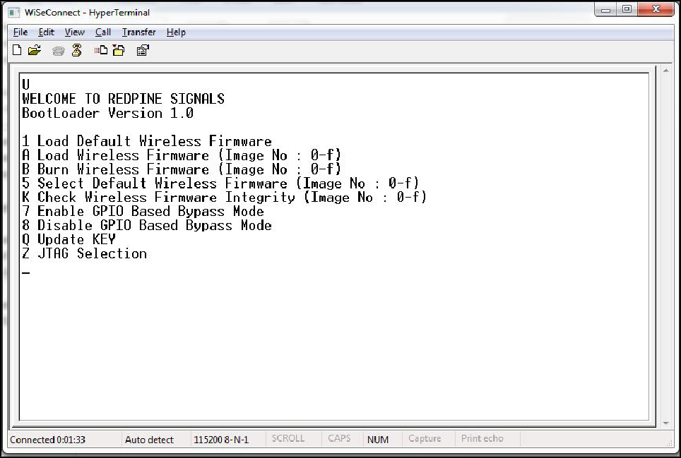
After powering up the module, do the ABRD process by giving "shift + | " followed by 'U'. Pipe symbol is shown below, you will see a welcome message on the host, followed by boot up options:
Note!
Windows Hyper Terminal is used to demonstrate the bootup and firmware update procedure.
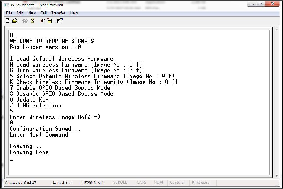
Loading the Default Wireless Firmware in the Module#
To load the default firmware flashed onto the module, choose Option 1: "Load Default Wireless Firmware ".
Load Default Wireless Firmware#
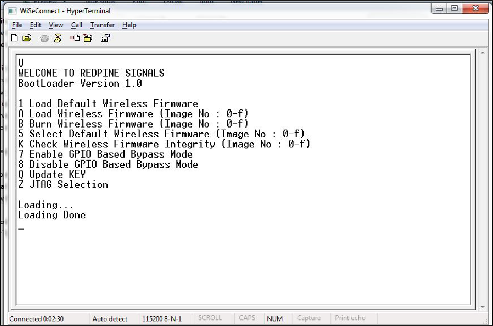
After the welcome message is displayed as shown in the above figure, select option 1 "Load Default Wireless Firmware" for loading Image.
Loading selected Wireless Firmware in the Module#
To load the selected firmware (from flash) onto the module, choose Option A: "Load Wireless Firmware ( Image No: 0-f )".
Load Wireless Firmware#
After the welcome message is displayed as shown in the above figure, select option A "Load Wireless Firmware ( Image No: 0-f )" for loading Image.
In response to the option A, Module asks to Enter Image No.
Select the image number to be loaded from flash.
After successfully loading the default firmware, "Loading Done" message is displayed.
After firmware loading is completed, the module is ready to accept commands.
Note!
To use host bypass mode, the user must select one of the images as default image by selecting option 5 (Select Default Wireless Firmware).
In Host interaction mode, if no option is selected after bootup menu for 20 seconds then the bootloader will load selected Wireless default image.
If the valid firmware is not present, then a message prompts "Valid firmware not present".
Firmware Update#
After powering up the module, a welcome message is displayed.
Update NWP firmware Image#
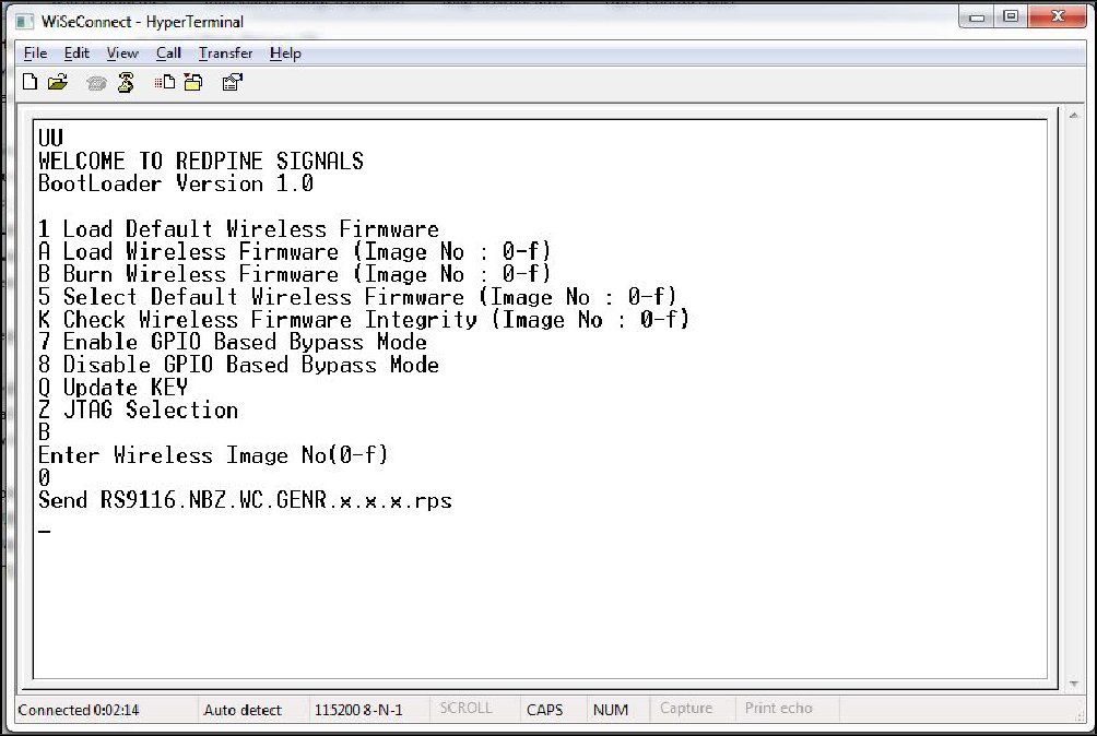
After the welcome message is displayed, select option B "Burn Wireless Firmware ( Image No: 0- f )" to update Wireless Image.
The message "Enter Wireless Image No ( 0-f )" is displayed.
Then select the Image no to be updated.
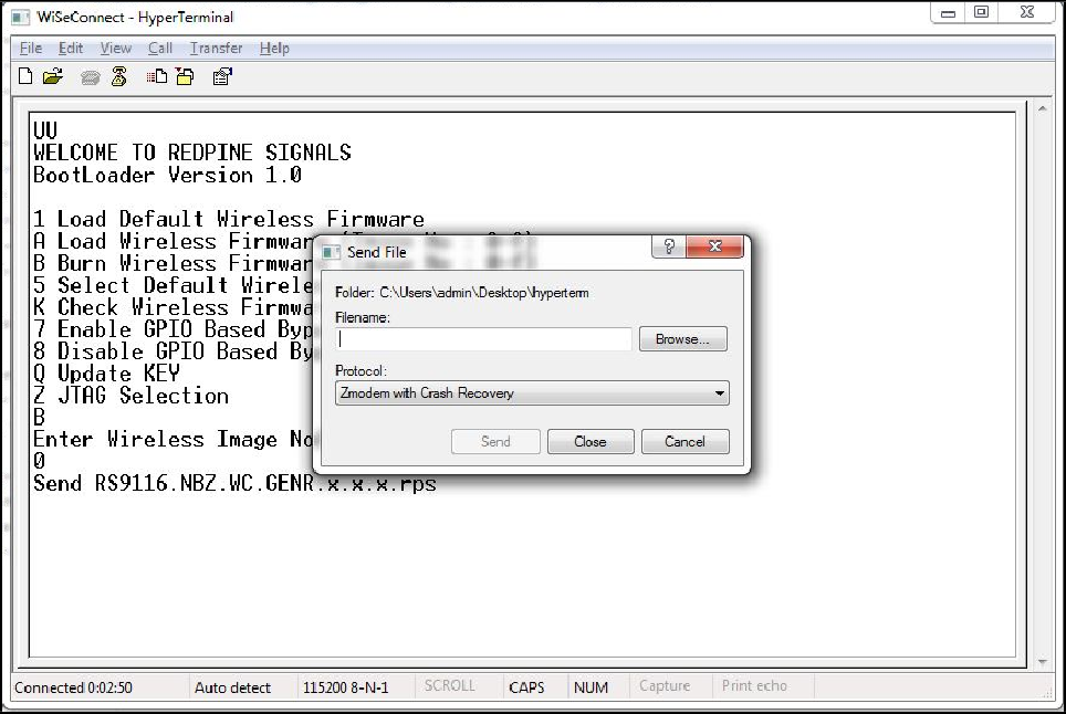
The message "Send RS9116.NBZ.WC.GENR.x.x.x.rps" should appear as shown in the figure below.
Note!
While using Tera Term, it is recommended to configure transmit delay to avoid file transfer to freeze.
After detection of serial port, change transmit delay from 0 msec/line to 1 msec/line to get 'firmware upgradation successful' as shown in the figure below.
In the "File" menu of HyperTerminal, select the "send file" option. A dialog box will appear as shown in the figure below. Browse to the path where "RS9116.NBZ.WC.GENR.X.X.X.rps" is located and select Kermit as the protocol option. After this, click the "Send" button to transfer the file.
If the valid firmware is not present, then a message prompts "Valid firmware not present".
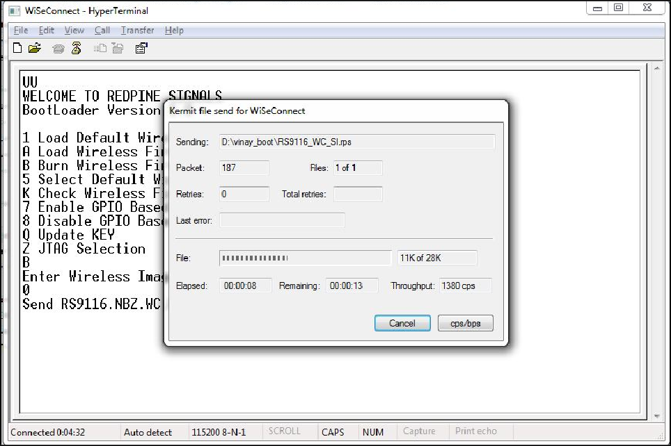
The dialog box message is displayed while file transfer is in progress as shown in the figure below.
After successfully completing the file transfer, module computes the integrity of the image and displays "Update Failed, re-burn the image" in case of failure. It displays "Update Failed and default image invalid, Bypass disabled" in case of both failure and corruption of the default image.
In the case of success, module checks if the bootloader bypass is enabled and computes the integrity of the default image selected. If the integrity fails, it sends "Update successful, Default image invalid, gpio bypass disabled." If integrity passes or GPIO bypass not enabled, it sends "Update Successful" message on the terminal as shown in the figure below.
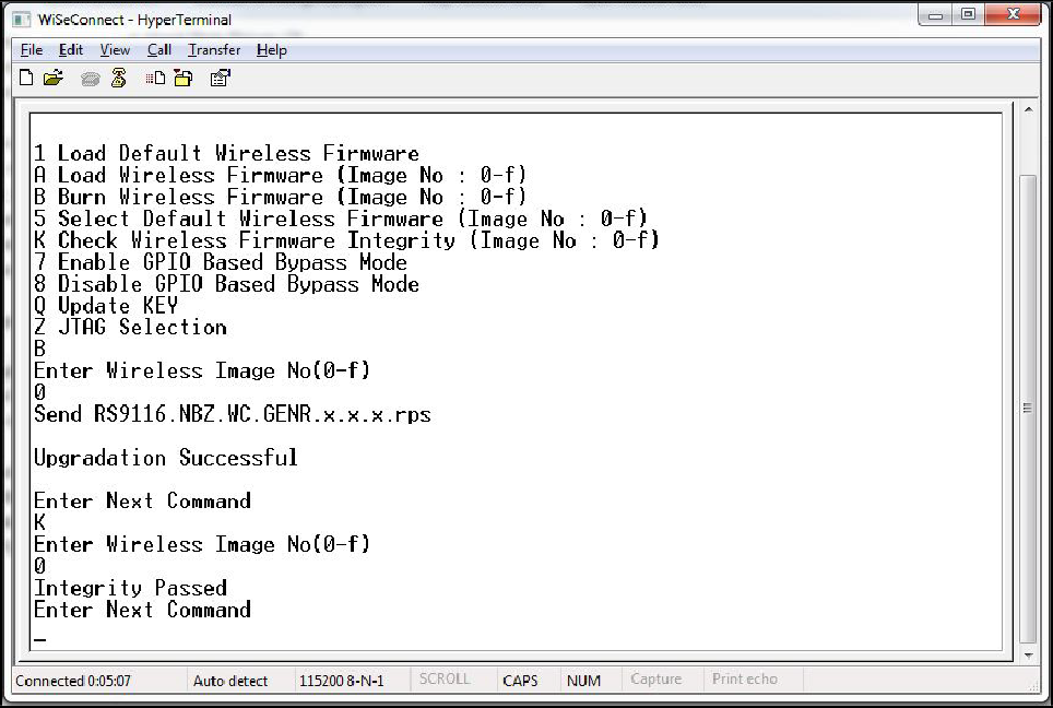
At this point, the updated firmware Image is successfully flashed to the module.
The user can again cross check the integrity of the Image by selecting the Option K "Check Wireless Firmware Integrity (Image No: 0-f )" for Wireless Image.
Follow the steps mentioned in Loading the Default Wireless Firmware in the Module to load thefirmware from flash, select Option 1 from the above figure.
The module is ready to accept commands from the Host.
Bypass Mode#
In GPIO based bootloader bypass mode host interactions with bootloader can be bypassed. There are two steps to enable GPIO based Bootloader bypass mode:
The host needs to select default wireless image to load in bypass mode.
Enable Bootloader bypass mode.
Assert
UULP_GPIO_2to Bypass Bootloader upon powerup.
To enable Bootloader Bypass mode, the host first has to give default image that has to be loaded in bypass mode and select the bypass mode(enable). After rebooting the module, it goes to bypass mode and directly loads the default firmware image.
Making Default Wireless Firmware Selection#
With this option, host can select the default firmware image to be loaded.
Selecting a valid Image as the Default Image#
After the welcome message is displayed, user can select option 5 "Select Default Wireless Firmware ( Image No: 0-f )".
The message "Enter Wireless Image No. ( 0-f )" is displayed.
Then select the Image number
It is better to check the Integrity of Image before selecting it as Default Image.
When default image is selected, module checks for the validity of the image selected and displays "Configuration saved".
Enable/Disable GPIO Based Bypass Option#
This option is for enabling or disabling the GPIO bootloader bypass mode.
Enabling the GPIO Based Bypass Mode#
If user select option 7, GPIO based Bootloader bypass gets enabled. When this option is selected, module checks for the validity of the image selected and displays "Configuration saved" if valid and "Default image invalid" if valid default image is not present. Once enabled, from next bootup, Bootloader will latch the value of UULP_GPIO_2. If asserted, it will bypass the whole boot loading process and will load the default firmware image selected.
After the welcome message is displayed, user can select option 5 "Select Default Wireless Firmware ( Image No: 0-f )".
The message "Enter Wireless Image No. ( 0-f )" is displayed.
Then select the Image no.
It is better to check the Integrity of Image before selecting it as Default Image.
When default image is selected, module checks for the validity of the image selected and displays "Configuration saved".
Then select option 7 to "Enable GPIO Based Bypass Mode"
Module responds to select the host interface in Bypass mode ( 0 - UART, 1 - SDIO, 2 - SPI, 4 - RESERVED, 5 - USB-CDC)
Select the required interface.
If the default image is valid, then it enables GPIO Bypass mode, otherwise it will not enable the GPIO Bypass mode.
Note!
The baud rate at which GPIO Based Bypass Mode is enabled becomes the default baud rate for further boot-ups until and unless GPIO Based Bypass Mode is disabled.
Disabling the GPIO Based Bypass Mode#
If the host selects option 8, GPIO based bypass gets disabled.
Note!
UULP_GPIO_2 needs to be de-asserted upon power up to move to host interaction mode, to select bootup options like disable Bypass mode or to change the default image.
Check Integrity of the Selected Image#
This option enables the user to check whether the given image is valid or not. When this command is given, bootloader asks for the image for which integrity has to be verified as shown in the figure below.