WLAN Commands#
The following sections document RS9116 WiSeConnect commands, parameters, responses and availability. For error codes returned by commands, see https://docs.silabs.com/rs9116-wiseconnect/latest/wifibt-wc-sapi-reference/error-codes
Index#
Group | AT Command API | Description |
|---|---|---|
Configuration & Setup | ||
Configure AP Mode | ||
Set Rx/Tx/Global buffer ratio | ||
Enable Auto-Join / Auto-Create | ||
Read Stored Configuration Parameters | ||
Store Configuration Parameters | ||
Store Server IP and Port Parameters | ||
Store Server IPv6 and Port Parameters | ||
Get the stored server IP details from the flash | ||
WLAN Configuration | ||
Set Broadcast Filter threshold | ||
Initialise PHY and Radio | ||
Query MAC Address | ||
Operating Mode | ||
Soft Reset | ||
Set MAC Address | ||
Trigger Auto Configuration | ||
Store User Configuration Parameters | ||
Firmware Update | ||
Wireless Firmware Update | ||
Query Firmware Version | ||
Update firmware via HTTP | ||
Update firmware via TCP | ||
Networking Protocols and Data Transfer | ||
FTP Client | ||
Close Socket | ||
Set HTTP server credentials | ||
Query TCP Server Socket Status | ||
DNS Resolution | ||
DNS Server | ||
DNS Update | ||
Write Dynamic Webpage | ||
Abort HTTP GET/POST | ||
HTTP Get | ||
HTTP Post | ||
HTTP Post Data | ||
HTTP Put | ||
Set IP Parameters | ||
Set IPv6 Parameters | ||
mDNS/DNS-SD Client | ||
MQTT Client | ||
Multicast Filter | ||
Join/Leave Multicast Group | ||
Query Network Parameters | ||
ICMP Ping | ||
Read Data | ||
Send Data | ||
SNTP Client | ||
Socket Configuration Parameters | ||
Open a Socket | ||
Transparent Serial passthrough mod | ||
Write Static Webpage | ||
Peripherals & Time | ||
Get RTC time | ||
Get RAM Dump | ||
UART Hardware flow Control | ||
Set RTC time | ||
Powersave | ||
Power Mode | ||
Set Sleep Timer | ||
WMM Powersave | ||
Radio Configuration | ||
Select Antenna | ||
Radio Band | ||
Write Calibration Data | ||
Set Feature Frame (radio parameters) | ||
Frequency Offset Correction | ||
Configure Gain Table | ||
Set Regulatory domain for Client Mode | ||
Set Regulatory Domain for AP Mode | ||
Security | ||
WEP Authentication Mode | ||
Set Certificate with Index | ||
Set TLS Certificate | ||
EAP Configuration | ||
Set WEP Keys | ||
WPS Pin Method | ||
Test & PER | ||
Query Socket Transmit byte count | ||
Erase All Webpages | ||
Configure UART Debug Prints | ||
Erase Static Webpage | ||
Erase Dynamic Webpage | ||
Get WLAN Statistics | ||
PER Mode Transmit Test | ||
Query PER Statistics | ||
Webpage Passthrough | ||
Wi-Fi Connection | ||
Background Scan | ||
Wi-Fi Disassociate | ||
High-throughput Capabilities | ||
Wi-Fi Join | ||
Wi-Fi Preshared Key | ||
Wi-Fi Rejoin | ||
Roam Parameters | ||
Wi-Fi Scan | ||
Set WLAN Connection Timeouts |
.
AT Command API (Asynchronous Responses) | Description |
|---|---|
Client Connection Change Notifications (AP mode) | |
AP Connection Change Notifications (Client mode) | |
IP Change Notification | |
Remote Socket Close Notification | |
Receive data on socket Notification | |
TCP Socket Established Notification |
Note!
All commands must be terminated with
\r\n(CRLF).
rsi_opermode :: Operating Mode#
Description#
This is the first AT command that needs to be sent from the Host after receiving the card ready frame from the module. This command configures the module in different functional modes.
Command Format#
Note that all parameters are shown on a new line to make the command format easier to read.
at+rsi_opermode=<oper_mode>,
<feature_bit_map>,
<tcp_ip_feature_bit_map>,
<custom_feature_bit_map>,
<ext_custom_feature_bit_map>,
<bt_feature_bit_map>,
<ext_tcp_ip_feature_bit_map>,
<ble_feature_bit_map>,
<ble_coustom_ext_feature_bit_map>,
<config_feature_bit_map>Some arguments for the rsi_opermode command are only enabled when conditions according to the following table are met.
The argument ... | is enabled when ... |
|---|---|
|
|
|
|
|
|
|
|
|
|
|
|
Parameters#
oper_mode
Sets the mode of operation.
<oper_mode>contains two parts <wifi_oper_mode,coex_mode>. The lower two bytes representswifi_oper_modeand higher two bytes representscoex_modes.
oper_mode = ((wifi_oper_mode) | (coex_mode << 16))where ...
| Meaning | Description |
|---|---|---|
0 | Wi-Fi Client Mode | The module works as a normal client that can connect to an Access Point with different security modes other than enterprise security. |
2 | Enterprise Security Client Mode | The module works as a client that can connect to an Access Point with WPA/WPA2-Enterprise security. |
6 | Access Point mode | In this mode, the module acts as an Access Point, depending on the inputs supplied for the command 'Configure AP Mode'. In Access Point mode, a Maximum of 16 clients can connect based on the bits set in custom feature bit map selection in opermode. Enable DHCP server by tcp_ip_feature_bit_map. |
8 | PER Mode. | This mode is used for calculating packet error rate and mostly used during RF certification tests. |
9 | Concurrent mode | This mode is used to run module in concurrent mode. In concurrent mode, host can connect to a AP and can create AP simultaneously. |
Note!
Opermode WiFi-Direct(1) mode is not supported.Note!
When operating in Concurrent Mode:
Upto 4 station devices can be connected to Concurrent AP.
The STA and AP may operate in different security modes.
The AP's MAC address can be determined by incrementing the last byte of STA's MAC address by
1.In TCP/IP non-bypass mode, Broadcast / Multicast packet goes to first created interface (e.g. if station connects first, the broadcast / multicast packet goes to the network that belongs to station).
Background scan, aggregation or IPv6 are not supported.
The station and AP interfaces must be configured to the same channel.
If AP is started first and selected channel scan is issued, it may return results from other channels. However, it is only possible to join in Concurrent AP's channel.
If STA is connected first, then AP should be explicitly started in the same channel as STA. Auto channel selection (channel 0) for AP is not supported in this case.
If AP and STA are running and the channel of external AP (to which the concurrent STA is connected) is changed, then the STA may attempt to rejoin in the old channel only.
coex_mode | Description |
|---|---|
0 | WLAN |
5 | WLAN + Bluetooth |
9 | WLAN + Dual Mode |
13 | WLAN + BLE |
Note!
Co-ex modes are supported only in 384K memory configuration.
For WLAN Co-ex mode, AP mode scan is not allowed.
If Co-ex mode is enabled in opermode command, then BT / BLE protocol will start and give corresponding card ready in parallel with opermode command response (which will be handled by corresponding application). BT card ready frame is described in the RS9116W BT Classic AT Command Programming Reference Manual and BLE card ready frame is described in the RS9116W BLE AT Command Programming Reference Manual
Other Parameters#
<feature_bit_map>, see feature_bit_map.<tcp_ip_feature_bit_map>, see tcp_ip_feature_bit_map.<custom_feature_bit_map>, see custom_feature_bit_map.<ext_custom_feature_bit_map>, see ext_custom_feature_bit_map.<bt_feature_bitmap>, see bt_feature_bitmap.<ext_tcpip_feature_bitmap>, see ext_tcpip_feature_bitmap.<ble_feature_bit_map>, see ble_feature_bit_map.<ble_custom_ext_feature_bit_map>, see ble_custom_ext_feature_bit_map.<config_feature_bitmap>, see config_feature_bitmap.
Response#
Result Code | Description |
|---|---|
| Success |
| Failure |
Possible error codes are 0x0021, 0x0025, 0xFF73, 0x002C, 0xFF6E, 0xFF6F, 0xFF70, 0xFFC5.
Example 1#
When only oper_mode is given in Command Format
Command
at+rsi_opermode=0
0x61 0x74 0x2B 0x72 0x73 0x69 0x5F 0x6F 0x70 0x65 0x72 0x6D 0x6F 0x64 0x65 0x3D 0x30 0x0D 0x0AResponse
OK
0x4F 0x4B 0x0D 0x0AExample 2#
When other parameters along with mode_val is given in opermode Command Format
This command configures the device into Wi-Fi client mode with HTTP server enabled in Open security mode.
at+rsi_opermode=0,1,2,0
0x61 0x74 0x2B 0x72 0x73 0x69 0x5F 0x6F 0x70 0x65 0x72 0x6D 0x6F 0x64 0x65 0x3D 0x30 0x2C 0x31 0x2C 0x32 0x2C 0x30 0x0D 0x0A[ Go to top ]
rsi_band :: Radio Band#
Description#
This command configures the radio band. This command has to be issued after opermode command.
at+rsi_band=<band_value>Parameters#
The valid values for the parameter for this command are as follows:
band_value (1 byte)
band_value | Functionality |
|---|---|
0 | 2.4 GHz |
1 | 5 GHz |
2 | Dual band (2.4 GHz and 5 GHz) |
Note!
Dual band is supported in station mode
802.11J is only supported in 5 GHz
Response#
Result Code | Description |
|---|---|
| Success |
| Failure |
Possible error codes are 0x0005, 0x0021, 0x0025, 0x002C, 0x003c.
Availability#
This command is available in all operating modes.
Example#
Command
at+rsi_band=0
0x61 0x74 0x2B 0x72 0x73 0x69 0x5F 0x62 0x61 0x6E 0x64 0x3D 0x30 0x0D 0x0AResponse
OK
0x4F 0x4B 0x0D 0x0A[ Go to top ]
rsi_config :: WLAN Configuration#
Description#
This command configures WLAN parameters. This command must be issued after init command.
Command Format#
at+rsi_config=<config_type>,<config_val>Parameters#
config_type (2 bytes)
1- Configure RTS (Request to send) threshold value other values are reserved for future use.
config_value (2 bytes)
0-2347- Range of RTS (Request to send) threshold value
Note! Only RTS_THRESHOLD config type is supported.
Response#
Result Code | Description |
|---|---|
| Success |
| Failure |
Possible error codes are 0x0063, 0x0064.
Availability#
This command is available in all operating modes.
Example#
Command
at+rsi_config=1,256
0x61 0x74 0x2B 0x72 0x73 0x69 0x5F 0x63 0x6F 0x6E 0x66 0x69 0x67 0x3D 0x31 0x2C 0x32 0x35 0x36 0x0D 0x0AResponse
OK
0x4F 0x4B 0x0D 0x0A[ Go to top ]
rsi_setmac :: Set MAC Address#
Description#
This command sets the MAC address of module. This command must be issued before the rsi_band command.
Command Format#
at+rsi_setmac=<mac_address>Parameters#
mac_address (6 bytes)
MAC address to be set for module.
Note! In concurrent mode, given MAC is applied to station mode and AP mode MAC address last byte will differ from station mode MAC. AP mode MAC address last byte will be one plus the station mode MAC address last byte given by host.
Response#
Result Code | Description |
|---|---|
| Success |
| Failure |
Possible error codes are 0x0021, 0x0025, 0x002C.
Availability#
This command is available in all operating modes.
Example#
Command
at+rsi_setmac=001122334455
0x61 0x74 0x2B 0x72 0x73 0x69 0x5F 0x73 0x65 0x74 0x6D 0x61 0x63 0x3D 0x30 0x30 0x31 0x31 0x32 0x32 0x33 0x33 0x34 0x34 0x35 0x35 0x0D 0x0AResponse
OK
0x4F 0x4B 0x0D 0x0A[ Go to top ]
rsi_init :: Initialize PHY and Radio#
Description#
This command programs Baseband and RF components of the module and returns the MAC address of module to the host. This command must be issued after band command.
Command Format#
at+rsi_initParameters#
None.
Response#
For Non-concurrent Mode#
Result Code | Description |
|---|---|
OK <MAC_Address> | MAC address of the module. In concurrent mode, two MAC addresses are returned, MAC_Address1 is the station MAC address and MAC_Address2 is the created AP MAC address. MAC address is returned in 6-bytes in hex format. |
| Failure. |
For Concurrent Mode#
| Result Code | Description |
| OK <MAC_Address1><MAC_Address2>| Successful execution of command. MAC_Address1 is the station MAC Address and MAC_Address2 is of the AP created in the module.|
| ERROR <Error code> | Failure. |
Possible error codes are 0x0021, 0x0025, 0x002C, 0x0002.
Availability#
This command is available in all operating modes
Example 1 - Client or AP mode#
Command
at+rsi_init
0x61 0x74 0x2B 0x72 0x73 0x69 0x5F 0x69 0x6E 0x69 0x74 0x0D 0x0AResponse
OK <MAC_Address>
0x4F 0x4B 0x80 0xC9 0x55 0x34 0xF0 0x10 0x0D 0x0AExample 2 - Concurrent mode#
at+rsi_init
0x61 0x74 0x2B 0x72 0x73 0x69 0x5F 0x69 0x6E 0x69 0x74 0x0D 0x0AResponse
OK <MAC_Address1><MAC_Address2>
0x4F 0x4B 0x80 0xC9 0x55 0x34 0xF0 0x10 0x80 0xC9 0x55 0x34 0xF0 0x11 0x0D 0x0A[ Go to top ]
rsi_gain_table :: Configure Gain Table#
Description#
This command overwrites the default region based gain tables (present in firmware) with user-defined region based gain tables. The 2.4 GHz and 5 GHz gain tables can be loaded consecutively by changing the band. This command should be issued immediately after the init command. Customer can load the two gain tables (i.e., 2.4GHz-20Mhz, 5GHz-20Mhz) one after other by changing band.
Note! Internally, firmware maintains two tables : Worldwide table and Region-based table. Worldwide table is populated by firmware with Max power values that chip can transmit that meets target specifications like EVM. Region-based table has default gain value set.
When certifying with user antenna, Region must be set to Worldwide and sweep the power from 0 to 21 dBm. Arrive at max power level that is passing certification especially band-edge.
These FCC/ETSI/TELEC/KCC Max power level should be loaded in end-to-end mode via WLAN User Gain table. This must be called done every boot-up since this information is not saved inside flash. Region based user gain table sent by application is copied onto Region based table .SoC uses this table in FCC/ETSI/TELEC/KCC to limit power and not to violate allowed limits.
For Worldwide region, the firmware uses Worldwide table for Tx. For other regions (FCC/ETSI/TELEC/KCC), the firmware uses min value out of Worldwide & Region based table for Tx. Also, there will be part to part variation across chips and offsets are estimated during manufacturing flow which will be applied as correction factor during normal mode of operation. This frame must be used by customers who has done FCC/ETSI/TELEC/KCC certification with their own antenna. All other customers should not use this. Inappropriate use of this frame may result in violation of FCC/ETSI/TELEC/KCC or any certifications, and Silicon Labs is not liable for that.
Precondition#
This command can be issued any time before or after the rsi_opermode command.
Command Format#
at+rsi_gain_table=<band_value>,<bandwidth>,<payload_length>,<payload>Parameters#
band_value (1-byte)
band_value | Frequency Band |
|---|---|
1 | 2.4 GHz |
2 | 5 GHz |
bandwidth (1-byte)
Mode | Bandwidth |
|---|---|
0 | 20 MHz |
1 | Reserved. |
payload_length (2-bytes)
Max table size in 2.4 GHz band is 128 bytes
Max table size in 5 GHz band is 64 bytes
payload (n-bytes, see table)
Pass channel gain values for different regions in the format shown as follows.
Gain table Format for 2.4 GHz band.
Each entry in the table is 1 byte.
In the 2.4 GHz, the maximum Gain/Power obtained from certification must be multiplied by 2.
<TABLE NAME>[] =
{
<NUMBER OF REGIONS>,
<REGION NAME 1>,
<CHANNEL CODE 2G>,
<CHANNEL NUMBER 1>, <2 * MAX POWER 11b RATE>, <2 * MAX POWER 11g RATE>, <2 * MAX POWER 11n RATE>,
<CHANNEL NUMBER 2>, <2 * MAX POWER 11b RATE>, <2 * MAX POWER 11g RATE>, <2 * MAX POWER 11n RATE>,
...
<CHANNEL NUMBER m-1>, <2 * MAX POWER 11b RATE>, <2 * MAX POWER 11g RATE>, <2 * MAX POWER 11n RATE>,
<CHANNEL NUMBER m>, <2 * MAX POWER 11b RATE>, <2 * MAX POWER 11g RATE>, <2 * MAX POWER 11n RATE>,
<REGION NAME 2>,
<CHANNEL_CODE_2G>,
<CHANNEL NUMBER 1>, <2 * MAX POWER 11b RATE>, <2 * MAX POWER 11g RATE>, <2 * MAX POWER 11n RATE>,
<CHANNEL NUMBER 2>, <2 * MAX POWER 11b RATE>, <2 * MAX POWER 11g RATE>, <2 * MAX POWER 11n RATE>,
...
<CHANNEL NUMBER m-1>, <2 * MAX POWER 11b RATE>, <2 * MAX POWER 11g RATE>, <2 * MAX POWER 11n RATE>,
<CHANNEL NUMBER m>, <2 * MAX POWER 11b RATE>, <2 * MAX POWER 11g RATE>, <2 * MAX POWER 11n RATE>,
...
};Gain table Format for 5 GHz band
In 5GHz, Max Gain/Power obtained from certification should be loaded.
Each entry in the table is 1 byte.
<TABLE NAME>[] =
{
<NUMBER OF REGIONS>,
<REGION NAME 1>,
<CHANNEL CODE 5G>,
<CHANNEL NUMBER IN BAND 1 IF ANY> / <BAND NUMBER 1>, <MAX POWER 11a RATE>, <MAX POWER 11n RATE>,
<CHANNEL NUMBER IN BAND 2 IF ANY> / <BAND NUMBER 2>, <MAX POWER 11a RATE>, <MAX POWER 11n RATE>,
<CHANNEL NUMBER IN BAND 3 IF ANY> / <BAND NUMBER 3>, <MAX POWER 11a RATE>, <MAX POWER 11n RATE>,
<CHANNEL NUMBER IN BAND 4 IF ANY> / <BAND NUMBER 4>, <MAX POWER 11a RATE>, <MAX POWER 11n RATE>
...
<REGION NAME 2>,
<CHANNEL CODE 5G>,
<CHANNEL NUMBER IN BAND 1 IF ANY> / <BAND NUMBER 1>, <MAX POWER 11a RATE>, <MAX POWER 11n RATE>,
<CHANNEL NUMBER IN BAND 2 IF ANY> / <BAND NUMBER 2>, <MAX POWER 11a RATE>, <MAX POWER 11n RATE>,
<CHANNEL NUMBER IN BAND 3 IF ANY> / <BAND NUMBER 3>, <MAX POWER 11a RATE>, <MAX POWER 11n RATE>,
<CHANNEL NUMBER IN BAND 4 IF ANY> / <BAND NUMBER 4>, <MAX POWER 11a RATE>, <MAX POWER 11n RATE>
...
};<REGION NAME #>
Substitute the <REGION NAME #> corresponding to the desired region.
REGION NAME # | Region |
|---|---|
0 | FCC |
1 | ETSI |
2 | TELEC |
4 | KCC |
<CHANNEL CODE 2G>
An 8-bit value encoded as follows:
If the transmit power of all the channels are the same, use
<CHANNEL_CODE_2G>=17and<CHANNEL NUMBER>=255.If the transmit power is not the same for all channels, use
<CHANNEL_CODE_2G>as number of channels and specify transmit power values for all channels.
<CHANNEL CODE 5G>
An 8-bit value encoded as number of rows in a region 5 GHz band.
5 GHz is divided into 4 sub bands
band 1: channel number <= 48
band 2: channel number > 48 and channel number <= 64
band 3: channel number > 64 and channel number <= 140
band 4: channel number > 140
If any channel in a specific band has a differing set of power values, specify the channel number followed by the power values.
If all channels in band
Xhave identical power values, specify the band number asXfollowed by the power value.
Note!
As worldwide certification is not possible, a gain table for worldwide is not applicable.
Length of the
<payload>must match with the<payload_len>parameter value.
Response#
Result Code | Description |
|---|---|
| Success |
| Failure |
Possible error codes are 0x0021, 0x003E.
Availability#
This command is available in WLAN operating modes.
Example#
Command
at+rsi_gain_table=1,0,67,<payload>Note!
For the
<payload_len>parameter, the user must provide the actual length of the payload. If the gain table length is 70 and the user enters 128 then the module will return an error (0x003E).To calculate the value of
<payload_len>, add the number of bytes in the<payload>excluding spaces and commas.
Response
OK
0x4F 0x4B 0x0D 0x0APayload Examples#
This is a payload example for:
band = 2.4 GHz
bandwidth = 20 MHz
{ 3, // Number of Regions
FCC, // Region Name
13, // Number of channels
1, 34, 20, 20, // rate, 11b, 11g, 11n
2, 34, 28, 28,
3, 34, 32, 32,
4, 34, 36, 36,
5, 34, 38, 38,
6, 34, 40, 40,
7, 34, 38, 38,
8, 34, 36, 36,
9, 34, 32, 32,
10, 34, 32, 32,
11, 34, 24, 24,
12, 34, 16, 24,
13, 34, 12, 12,
TELEC, // Region Name
17, // Number of channels
255, 20, 16, 16, // rate, 11b, 11g, 11n
KCC, // Region Name
17, // Number of channels
255, 26, 20, 20, // rate, 11b, 11g, 11n
}This is a payload example for:
band = 5 GHz
bandwidth = 20 MHz
{
2, // Number of Regions
FCC, // Region Name
6, // Number of rows in 5 GHz region
1, 9, 10, // band 1
2, 8, 9, // band 2
100, 4, 4, // band 3
3, 6, 8, // band 3
149, 3, 3, // band 4
4, 6, 7, // band 4
TELEC, // Region Name
4, // Number of rows in 5 GHz region
1, 9, 10, // band 1
2, 8, 10, // band 2
3, 6, 8, // band 3
4, 6, 7, // band 4
}Example 2#
Customers using Certified MARS antenna should use the following gain table.
This is a payload example for:
band = 2.4 GHz
bandwidth = 20 MHz
{
3, // Number of Regions
FCC, // Region Name
13, // Number of channels
1, 28, 32, 30, // rate, 11b, 11g, 11n
2, 28, 32, 30,
3, 28, 32, 30,
4, 30, 28, 34,
5, 30, 28, 34,
6, 30, 28, 34,
7, 30, 28, 34,
8, 30, 28, 34,
9, 28, 30, 30,
10, 28, 30, 30,
11, 28, 30, 30,
12, 28, 30, 30,
13, 28, 30, 30,
TELEC, // Region Name
17, // Number of channels
255, 20, 16, 16, // rate, 11b, 11g, 11n
KCC, // Region Name
17, // Number of channels
255, 26, 20, 20, // rate, 11b, 11g, 11n
};This is a payload example for:
band = 5 GHz
bandwidth = 20 MHz
{
2, // Number of Regions
FCC, // Region Name
6, // Number of rows
1, 12, 12, // band 1
2, 11, 11, // band 2
100, 10, 12, // band 3
3, 13, 13, // band 3
140, 10, 11, // band 4
4, 13, 13, // band 4
TELEC, // Region name
4, // Number of rows in 5GHz region
1, 9, 10, // band 1
2, 8, 10, // band 2
3, 6, 8, // band 3
4, 6, 7, // band 4
}[ Go to top ]
rsi_per :: PER Mode/Transmit Test#
Description#
This command configures the PER (Packet Error Rate) Mode in RS9116-WiSeConnect. This command should be issued after rsi_init command.
Command Format#
at+rsi_per=<per_mode_enable>,<power>,<rate>,<length>,<mode>,<channel>,<rate_flags>,<aggr_enable>,<no_of_pkts>,<delay>Parameters#
per_mode_enable (2 bytes)
Enable or disable PER Mode.
0– Disable PER mode1– Enable PER mode
power (2 bytes)
Set transmit power in dbm. Valid values are from 2dBm to 18dBm.
Note!
To configure the maximum power level for a particular frequency band, set <power> = 127.
rate (4 bytes)
Set transmit data rate.
| Selected Data Rate (Mbps) |
|---|---|
|
|
|
|
|
|
|
|
|
|
|
|
|
|
|
|
|
|
|
|
|
|
|
|
|
|
|
|
|
|
|
|
|
|
|
|
|
|
|
|
Note!
Date rate of 1, 2, 5.5, 11 Mbps (i.e., rate parameter: 0, 2, 4, 6) are not supported when operating in 5 GHz channel.
length (2 bytes)
Configure length of the transmit packet. Valid values are in the range:
[24 .. 1500]bytes in burst mode[24 ... 260]bytes in continuous mode
mode (2 bytes)
Transmit mode
Mode | Transmit Mode |
|---|---|
| Burst Mode |
| Continuous Mode |
| CW Mode (unmodulated) in DC mode |
| CW Mode (unmodulated) with a single tone at: |
| CW Mode (unmodulated) with a single tone at: |
Note!
Burst Mode
DUT transmits a burst of packets with the given power, rate, length in the channel configured. The burst size will be determined by the <number of packets> and if its zero, then DUT keeps transmitting till a rsi_transmit_test_stop API is called.
Continuous Mode
The DUT transmits an unmodulated waveform continuously.
Continuous Wave Mode (Non-Modulation) in DC Mode:
The DUT transmits a spectrum only at the center frequency of the channel. A basic signal with no modulation is that of a sine wave and is usually referred to as a continuous wave (CW) signal. A basic signal source produces sine waves. Ideally, the sine wave is perfect. In the frequency domain, it is viewed as a single line at some specified frequency.
Continuous Wave Mode (Non-Modulation) in Single Tone Mode (Center frequency -2.5 MHz):
The DUT transmits a spectrum that is generated at -2.5 MHz from the center frequency of the channel selected. Some amount of carrier leakage will be seen at Center Frequency.
For example, for 2412 MHz the output will be seen at 2409.5 MHz
Continuous Wave Mode (Non-Modulation) in Single Tone Mode (Center frequency +5 MHz):
The DUT transmits a spectrum that is generated at 5MHz from the center frequency of the channel selected. Some amount of carrier leakage will be seen at Center Frequency.
For example, for 2412 MHz the output will be seen at 2417 MHz.
Note!
Before starting CW mode, it is required to start Continuous mode with power and channel values which is intended to be used in CW mode as follows:
Start Continuous mode with intended power value and channel value; pass any valid values for rate and length
Stop Continuous mode
Start CW mode.
To switch CW mode, stop PER mode and then give CW mode to where the user wants to switch to
Generally, it is recommended to measure the TX power with "Burst mode or Continuous mode" only. "Continuous wave mode" for TX power measurement is not recommended. "Continuous wave mode" can be used for certification purposes and that to measure the frequency error.
channel (2 bytes)
Sets the channel number in 2.4 GHz / 5 GHz. The following tables map the channel number to the actual radio frequency in the 2.4 GHz spectrum. To support PER mode in channels 12 and 13, the correct region command must be given by the host before the PER command.
Channel Number (2.4 GHz) | Center frequency in MHz for 20MHz channel width |
|---|---|
|
|
|
|
|
|
|
|
|
|
|
|
|
|
|
|
|
|
|
|
|
|
|
|
|
|
Channel numbers in the 5 GHz band are in the range 36 to 165. The following table maps the channel number to the actual radio frequency in the 5 GHz spectrum for 20MHz channel bandwidth.
Channel Number (5 GHz) | Center frequency in MHz for 20MHz channel width |
|---|---|
|
|
|
|
|
|
|
|
|
|
|
|
|
|
|
|
|
|
|
|
|
|
|
|
|
|
|
|
|
|
|
|
|
|
|
|
|
|
|
|
|
|
|
|
|
|
|
|
The following tables maps the channel number to the actual radio frequency in the 4.9 GHz spectrum for 802.11J. 802.11J features are only valid when the Japan region is set. For other regions, even if 802.11J is enabled, it has no effect.
Channel Number (4.9GHz) | Center frequency in MHz for 20MHz channel width |
|---|---|
|
|
|
|
|
|
|
|
|
|
|
|
|
|
rate_flags (2 bytes)
Rate flags contain short GI, Greenfield and channel width values. Various fields in
rate_flagsare divided as specified below:
Fields | Short GI | Greenfield | Channel Width | Reserved | Immediate Transfer | Reserved |
|---|---|---|---|---|---|---|
Bits |
|
|
|
|
|
|
Short GI. Set
rate_flags[0]=1to enable Short GI (Short GI is not available in all software releases).Greenfield. Set
rate_flags[1]=1to enable Greenfield mode.Channel width should be set to zero to set 20MHz channel width.
Reserved: This field can be ignored. Set '0'.
Immediate Transfer : CCA is enabled by default, set this bit to transfer packets immediately by ignoring CCA.
Reserved: This field can be ignored. Set '0'.
aggr_enable (2 bytes)
This parameter is for enabling or disabling aggregation support. Aggregation feature is supported only in burst mode. This field will be ignored in case of continuous mode.
no_of_pkts (2 bytes)
This parameter sets the number of packets to be sent in burst mode. If the value given is
nthennnumber of packets will be sent on air, after that transmission will be stopped. If this field is given as0then packets will be sent continuously until user stops the transmission. This field will be ignored in case of continuous mode.
delay (4 bytes)
This parameter is used to set the delay between packets in burst mode. Delay should be given in microseconds. i.e. if the value is given as
nthen a delay ofnmicroseconds will be added for every transmitted packet in burst mode.If this field is set to
0then packets will be sent continuously without any delay. This field will be ignored in case of continuous mode.
Note!
Only per_mode_enable, power, rate, length , mode, channel, rate_flags fields are valid. Remaining fields are not supported.
Response#
Result Code | Description |
|---|---|
| Success |
| Failure |
Possible error codes are 0x000A, 0x0021, 0x0025, 0x002C, 0x0033.
Availability#
This command is available when the module is configured in operating mode 8.
Example
To start transmitting
at+rsi_per=1,18,139,30,0,1,0,0,0,0
0x61 0x74 0x2B 0x72 0x73 0x69 0x5F 0x70 0x65 0x72 0x3D 0x31 0x2C 0x31 0x38 0x2C 0x31 0x33 0x39 0x2C 0x33 0x30 0x2C 0x30 0x2C 0x31 0x2C 0x30 0x2C 0x30 0x2C 0x30 0x2C 0x30 0x0D 0x0ATo stop transmitting
at+rsi_per=0
0x61 0x74 0x2B 0x72 0x73 0x69 0x5F 0x70 0x65 0x72 0x3D 0x30 0x0D 0x0AResponse#
OK
0x4F 0x4B 0x0D 0x0A[ Go to top ]
rsi_freq_offset :: Frequency Offset Correction#
Command Description#
This command is used during the RF calibration process and requires PER mode transmissions to be initiated prior. This command sends freq_offset (deviation) as observed on the signal analyzer against the expected channel frequency. This command is relevant in PER mode.
Command Format#
at+rsi_freq_offset=<freq_offset_in_khz>Parameters#
freq_offset_in_khz
Frequency deviation in kHz or ppm.
Response#
Result Code | Description |
|---|---|
| Success |
| Failure |
Possible error codes are 0x00FC, 0X00FB.
Availability#
This command is available when the module is configured in Operating Mode 8.
Example#
To send frequency offset as 10 ppm:
Command
at+rsi_freq_offset=10Response
OK[ Go to top ]
rsi_calib_write :: Write Calibration Data#
Description#
This API is used during the RF calibration process and requires PER mode transmissions to be initiated prior. This API will command the firmware to update the existing Flash/EFuse calibration data with the xo ctune (given or picked from hardware register) and gain offset values. This command is relevant in PER mode.
The rsi_freq_offset command needs to be called before this command when xo ctune value from hardware register is to be used.
Command Format#
at+rsi_calib_write=<target>,<flags>,<gain_offset_low>,<gain_offset_mid>,<gain_offset_high>,<xo_ctune>Parameters#
target (1 byte)
Sets the target for calibration data
0-BURN_INTO_EFUSE. Burns calibration data to EFuse1-BURN_INTO_FLASH. Burns calibration data to Flash
flags (1 byte)
Bit 0 =
RESERVED_0Reserved
Bit 1 =
BURN_FREQ_OFFSET0- Skip XO Ctune update1- Update XO Ctune to calibration data
Bit 2 =
SW_XO_CTUNE_VALID0- Use XO Ctune value as read from hardware register1- Use XO Ctune provided as argument to update calibration data
Bit 3 =
BURN_XO_FAST_DISABLEThis BIT is used to apply patch for cold temperature issue on CC0/CC1 module.
Bit 4 =
BURN_GAIN_OFFSET_LOW0- Skip low sub-band gain-offset update1- Update gain offset for low sub-band (2 GHz).
Bit 5 =
BURN_GAIN_OFFSET_MID0- Skip mid sub-band gain-offset update1- Update gain offset for mid sub-band (2 GHz).
Bit 6 =
BURN_GAIN_OFFSET_HIGH0- Skip high sub-band gain-offset update1- Update gain offset for high sub-band (2 GHz).
Bits 31-4 = Reserved
gain_offset_low (1 byte)
gain_offset as observed in dBm in channel-1
gain_offset_mid (1 byte)
gain_offset as observed in dBm in channel-6
gain_offset_high (1 byte)
gain_offset as observed in dBm in channel-11
xo_ctune (1 byte)
This field allows user to directly update
xo_ctunevalue to calibration data bypassing the freq offset loop, valid only whenBURN_FREQ_OFFSETandSW_XO_CTUNE_VALIDflags are set.
Note!
For gain-offset calibration in 2 GHz, the user needs to calibrate gain-offset for low sub-band (channel-1), mid sub-band (channel-6), and high sub-band (channel-11) and input the three gain-offsets to this command and set the corresponding flags to validate it#
Response#
Value | Description |
|---|---|
0 | Success |
Non Zero Value | Failure |
Example#
The gain offset can be calculated with the following equation.
gain_offset = observed_power_level + cable_loss - configured_power_levelwhere ...
observed_power_level = 14.3 dBm
cable_loss = 1.7 dB
configured_power_level = 18.0 dBm
To write the gain offset as -2 dBm into flash/efuse, use the following command.
at+rsi_calib_write=1,1,-2To write the xo_ctune value available in the hardware register to flash/efuse (after frequency calibration is performed), use the following command.
at+rsi_calib_write=1,2,0To write a user configured xo_ctune value to flash/efuse (without performing the frequency calibration process), use the following command. Note that xo_ctune is in the range [0..255].
at+rsi_calib_write=1,2,0,<xo_ctune>Note!
To recalibrate the gain offset after it has been burnt to flash, the gain offset must be reset first, followed by the standard calibration flow. Recalibration is not possible if the EFuse is being used instead of flash. To reset the gain offset, use rsi_calib_write = 1,1,0.
Response
OK[ Go to top ]
rsi_apconf :: Configure AP Mode#
Description#
This command is used to set the configuration information for AP mode. This command must be issued after the rsi_init command.
Command Format#
at+rsi_apconf = <channel_no>,<ssid>,<security_type>,<encrypt_type>,<psk>,<beacon_interval>,<dtim_period>,<sta support>,<ap_keepalive_type>,<ap_keepalive_period>Parameters#
channel_no (2 bytes)
The channel in which the AP operates. A value of zero enables the Auto channel selection (ACS) feature to automatically determine which channel configuration to use. The channel with the least traffic will be selected.
The following table maps the channel number to the actual radio frequency in the 2.4 GHz spectrum.
Channel Number (2.4GHz) | Center frequency in MHz for 20MHz channel width |
|---|---|
|
|
|
|
|
|
|
|
|
|
|
|
|
|
|
|
|
|
|
|
|
|
|
|
|
|
Note!
Operation in channels 12/13 requires configuration of the correct regulatory region using the set_region command.
The following table maps the channel number to the actual radio frequency in the 5 GHz spectrum.
Channel Number (5GHz) | Center Frequency in MHz for 20MHz channel width |
|---|---|
|
|
|
|
|
|
|
|
|
|
|
|
|
|
|
|
|
|
Note! DFS channels are not supported in AP mode.
ssid (34 bytes)
SSID of the AP to be created.
Note!
To support a comma
,in the SSID, enclose the SSID in double quotes e.g. “MY, NETWORK”Double quotes
"in the SSID are not supported.The maximum length of the SSID is 32 bytes; the remaining 2 bytes are reserved for NULL termination and internal alignment.
security_type (1 byte)
Security type
security_type | Security Type |
|---|---|
|
|
|
|
|
|
|
|
|
|
Note
For AP mode with WPA3 security, only SAE-H2E method is supported. SAE Hunting and pecking method is not supported.
PMKSA is not supported in WPA3 AP mode.
encrypt_type (1 byte)
Encryption type
Mode | Encryption |
|---|---|
|
|
|
|
|
|
Note
Bit 7 to 4 are being used for Transition Disable Indication(TDI).
TDI can be enable in WPA3(Personal or Personal Transition mode) security mode in AP if bit 4 is set.
psk (64 bytes)
PSK of the AP in security mode.
If the AP is in Open mode, this parameter can be set to
0.If the security mode is WPA/WPA2, the PSK must between 8 and 63 bytes.
beacon_interval (2 bytes)
Beacon interval of the AP in milliseconds. Allowed values are integers in the range 100 to 1000 in multiples of 100.
dtim_period (2 bytes)
DTIM period. Allowed values are from 1 to 255
ap_keepalive_type (1 byte)
This is the bitmap to enable AP keep alive functionality and to select the keep alive type.
BIT[0] - Enable/disable keep alive functionality.
0- To disable keep alive functionality1- To enable keep alive functionality
BIT[1] - Select AP keep alive method.
0- Default keep alive functionality i.e. disconnect the station if there are no wireless exchanges from station with in ap_keepalive_period1- Enable null data frame based keep alive functionality.
ap_keepalive_period (1 byte)
This is the period after which AP will disconnect the station if there are no wireless exchanges from station to AP. Keep alive period is calculated in terms of 32 multiples of beacon interval i.e if there are no wireless transfers from station to AP with in (
32xbeacon_interval=keep_alive_period) milliseconds time period, station will be disconnected. If null data based method is selected, AP checks the connectivity of station by sending null data packet. If station does not acknowledge the packet, that station will be disconnected from AP after 4 retries.
max_sta_support (2 bytes)
Number of clients supported. This value should be less than or equal to the value given in custom feature select bit map
BIT[13:16]of the Set Operating Mode command. If value is not set in custom feature select bit mapBIT[13:16]of the Set Operating Mode then maximum supported stations are 4.
Note! RS9116W supports for connecting 16 clients to the created AP by setting custom_feature_bit_map[13:16]](https://docs.silabs.com/rs9116-wiseconnect/latest/wifibt-wc-sapi-reference/opermode#rsi-custom-feature-bit-map) and extended_custom_feature_bit_map[15]](https://docs.silabs.com/rs9116-wiseconnect/latest/wifibt-wc-sapi-reference/opermode#rsi-ext-custom-feature-bit-map) by using the equation mentioned below:
Number of stations = (Stations Obtained by setting BIT[13-16] + 1 ) * 2For example, if the host wants 16 clients support in AP, then set following bits: BIT[13], BIT[14] and BIT[15] (leave BIT[16] as 0 ) in custom feature bitmap and BIT[15] in extended custom feature bitmap, then the number of stations will become (7+1) * 2 = 16. If configuring more than 16 stations, it will throw an error.
If the extended custom feature bitmap is not set, then it can configure a maximum of 8 stations. This is
Backward Compatibility. Also, if configuring more than 8 stations, it will throw an error
Response#
Result Code | Description |
|---|---|
| Success |
| Failure |
Possible error codes are 0x0021, 0x0025, 0x002C, 0x0026, 0x004C, 0x0028, 0x001A, 0x000A, 0x001D
Availability#
This command is available when the module is configured in Operating Mode 6 and 9.
Example 1#
Configured AP with:
channel_no: 11
ssid: ap_ssid
security_type: open mode
beacon_interval: 100
dtim_period: 3
max_sta_support: 3
Command
at+rsi_apconf=11,ap_ssid,0,0,0,100,3,3
0x61 0x74 0x2B 0x72 0x73 0x69 0x5F 0x61 0x70 0x63 0x6F 0x6E 0x66 0x3D 0x31 0x31 0x2C 0x72 0x65 0x64 0x70 0x69 0x6E 0x65 0x2C 0x30 0x2C 0x30 0x2C 0x30 0x2C 0x31 0x30 0x30 0x2C 0x33 0x2C 0x33 0x0D 0x0AResponse
OK
0x4F 0x4B 0x0D 0x0AExample 2#
Configured AP with:
channel_no: 0 (ACS)
ssid:
MY_SSIDsecurity_type: WPA2
encrypt_type: CCMP
psk: 12345678
beacon_interval: 100
dtim_period: 3
max_sta_support: 3
Command
at+rsi_apconf=0,MY_SSID,2,2,12345678,100,3,3
0x61 0x74 0x2B 0x72 0x73 0x69 0x5F 0x61 0x70 0x63 0x6F 0x6E 0x66 0x3D 0x30 0x2C 0x4D 0x59 0x5F 0x53 0x53 0x49 0x44 0x2C 0x32 0x2C 0x32 0x2C 0x31 0x32 0x33 0x34 0x35 0x36 0x37 0x38 0x2C 0x31 0x30 0x30 0x2C 0x33 0x2C 0x33 0x0D 0x0AResponse
OK
0x4F 0x4B 0x0A 0x00 0x0D 0x0A[ Go to top ]
rsi_wps_method :: WPS PIN Method#
Description#
This command configures the WPS PIN method to be used in RS9116-WiSeConnect.This command should be issued before join command.
Command Format#
at+rsi_wps_method=<wps_method>,<generate_pin>,<wps_pin>Parameters#
wps_method (2 bytes)
Set to '1' for PIN method.
generate_pin (2 bytes)
This parameter specifies whether to validate entered PIN or generate PIN. This parameter is valid only if
wps_methodis1.0- Use entered pin in wps_pin field1- PIN generation
If
generate_pinis0, module will validate the given 8 digitwps_pin. If pin given is less than 8 digit or if pin is wrong then module will give error.
wps_pin (8 bytes)
wps_pinis of 8 digits pin. Module validates and uses this pin only in case of whenwps_methodis PIN method andgenerate_pinis0.
Response#
Response contains a wps_pin payload only if PIN method is selected. In case of PUSH method response does
not contains any payload.
wps_pin: The WPS PIN will be used by the module to connect with WPS AP.
Result Code | Description |
|---|---|
| Success |
| Failure |
Possible error codes are 0x0021, 0x0025, 0x002C, 0x0037, 0x0038.
Availability#
This command is available when the module is configured in Operating Mode 0 and 6.
Example 1#
When PIN of length 8 is given:
Command
at+rsi_wps_method=1,0,12345678
0x61 0x74 0x2B 0x72 0x73 0x69 0x5F 0x77 0x70 0x73 0x5F 0x6D 0x65 0x74 0x68 0x6F 0x64 0x3D 0x31 0x2C 0x30 0x2C 0x31 0x32 0x33 0x34 0x35 0x36 0x37 0x38 0x0D 0x0AResponse
OK 0x01 0x02 0x03 0x04 0x05 0x06 0x07 0x08 0x4F 0x4B 0x01 0x02 0x03 0x04 0x05 0x06 0x07 0x08 0x0D 0x0AExample 2#
When PIN of length less than 8 is given:
Command
at+rsi_wps_method=1,1,1234
0x61 0x74 0x2B 0x72 0x73 0x69 0x5F 0x77 0x70 0x73 0x5F 0x6D 0x65 0x74 0x68 0x6F 0x64 0x3D 0x31 0x2C 0x30 0x2C 0x31 0x32 0x33 0x34 0x0D 0x0A[ Go to top ]
rsi_scan :: Wi-Fi Scan#
Description#
This command scans for Access Points and gives the scan results to the host. The scan results are sorted in decreasing order of signal strength (RSSI value). The scanned access point with highest signal strength will be the first in the list. This command has to be issued after init (#rsi_init---initialize-phy-and-radio) command and before join (#rsi_join---wifi-join) command.
Command Format#
There are two command format options available:
Scanning multiple channels
Scanning a specific channel
at+rsi_scan=<channel>,<ssid>,<channel_bit_map_2_4>,<channel_bit_map_5>
at+rsi_scan=<channel>,<ssid>,<scan_feature_bitmap>Parameters#
Channel (4 byte)
Channel Number on which scan has to be done. If this value is 0, the module scans in all the channels in the band that is selected through the band command. The values of this parameter are listed in table below To select DFS channels user need to set custom feature bit in opermode command.
Note!
If
chan_numis0and channel bit maps (selective scan) are provided, then module will scan only the channels specified in bitmaps instead of scanning all channels.In case of 5GHz, module performs passive scan in DFS channels only when
BIT[8]is set in custom feature bit map in Set Operating Mode command.scan feature bitmap
BIT[0](QUICK SCAN feature) - It is valid only if channel number and ssid is given.
If channel bitmap is specified, module will scan only channels which are valid in selected region
Channel Number (2.4 GHz) |
|
|---|---|
All channels | 0 |
1 | 1 |
2 | 2 |
3 | 3 |
4 | 4 |
5 | 5 |
6 | 6 |
7 | 7 |
8 | 8 |
9 | 9 |
10 | 10 |
11 | 11 |
12 | 12 |
13 | 13 |
Note! Scanning in 12, 13 channels is allowed based on the region selected in Set Region command.
Channel Number (5 GHz) |
|
|---|---|
All channels | 0 |
36 | 36 |
40 | 40 |
44 | 44 |
48 | 48 |
149 | 149 |
153 | 153 |
157 | 157 |
161 | 161 |
165 | 165 |
DFS Channel Number (5 GHz) |
|
|---|---|
52 | 52 |
56 | 56 |
60 | 60 |
64 | 64 |
100 | 100 |
104 | 104 |
108 | 108 |
112 | 112 |
116 | 116 |
120 | 120 |
124 | 124 |
128 | 128 |
132 | 132 |
136 | 136 |
140 | 140 |
Channel Number (4.9 GHz) |
|
|---|---|
All channels | 0 |
184 | 184 |
188 | 188 |
192 | 192 |
196 | 196 |
8 | 8 |
12 | 12 |
16 | 16 |
ssid (34 byte)
Optional Input. For scanning a hidden Access Point, its SSID can be provided as part of the SCAN command. The maximum number of scanned networks reported to the host is 11. If not used, null characters should be supplied to fill the structure.
Note!
To support a comma
,in the SSID, enclose the SSID in double quotes e.g. “MY, NETWORK”Double quotes
"in the SSID are not supported.The maximum length of the SSID is 32 bytes; the remaining 2 bytes are reserved for NULL termination and internal alignment.
scan_feature_bitmap (1 byte)
BIT[0]: Enable/disable quick scan feature.0 - Disable quick scan feature.
1 - Enable quick scan feature.
BIT[1:7]: Reserved
channel_bit_map_2_4 (2 bytes)
channel bitmap for scanning in set of selective channels in 2.4 GHz.
channel_bit_map_5 (4 bytes)
channel bitmap for scanning a set of selective channels in 5 GHz.
Note!
For 11J, channel bit map need to give in channel_bit_map_5.
Channel Number 2.4 GHz |
|
|---|---|
1 | 0 |
2 | 1 |
3 | 2 |
4 | 3 |
5 | 4 |
6 | 5 |
7 | 6 |
8 | 7 |
9 | 8 |
10 | 9 |
11 | 10 |
12 | 11 |
13 | 12 |
Channel Number (5 GHz) |
|
|---|---|
36 | 0 |
40 | 1 |
44 | 2 |
48 | 3 |
149 | 19 |
153 | 20 |
157 | 21 |
161 | 22 |
165 | 23 |
DFS Channel Number (5 GHz) |
|
|---|---|
52 | 4 |
56 | 5 |
60 | 6 |
64 | 7 |
100 | 8 |
104 | 9 |
108 | 10 |
112 | 11 |
116 | 12 |
120 | 13 |
124 | 14 |
128 | 15 |
132 | 16 |
136 | 17 |
140 | 18 |
Channel Number (4.9 GHz) |
|
|---|---|
8 | 0 |
12 | 1 |
16 | 2 |
184 | 3 |
188 | 4 |
192 | 5 |
196 | 6 |
Result Code | Description |
|---|---|
| Success |
| Failure |
where ...
scan_count (4 bytes)
Number of Access Points scanned
padding(4 bytes)
padding bytes which can be ignored.
rf_channel (1 byte)
Channel Number of the scanned Access Point
security_mode (1 byte)
Mode | Functionality |
|---|---|
0 | Open |
1 | WPA |
2 | WPA2 |
3 | WEP |
4 | WPA Enterprise |
5 | WPA2 Enterprise |
7 | WPA3 Personal Mode |
8 | WPA3 Personal Transition mode |
--- | |
Note!: |
In WPA3 Personal Transition Mode if both WPA2 and WPA3 APs are available in scan results, STA will pick the AP which has strongest RSSI (it could be either WPA2 or WPA3).
rssi_val (1 byte)
RSSI of the scanned Access Point
u_network_type(1 byte)
Network type of the scanned Access Point 1– Infrastructure mode
ssid (34 bytes)
SSID of the scanned Access Point
bssid (6 bytes)
MAC address of the scanned Access Point.
reserved (2 bytes)
Reserved bytes.
Availability#
This command is available when the module is configured in Operating Mode 0, 2, 6 and 9.
Examples#
To scan all the networks in all channels
Command
at+rsi_scan=0
0x61 0x74 0x2B 0x72 0x73 0x69 0x5F 0x73 0x63 0x61 0x6E 0x3D 0x30 0x0D 0x0ATo scan a specific network "Test_AP" in a specific channel 6
Command
at+rsi_scan=6,Test_AP
0x61 0x74 0x2B 0x72 0x73 0x69 0x5F 0x73 0x63 0x61 0x3D 0x36 0x2C 0x54 0x65 0x73 0x74 0x5F 0x41 0x50 0x0D 0x0AResponse If two networks are found with the SSID "ap_ssid_net1" and "ap_ssid_net2" in channels 6 and 10, with measured RSSI of -20dBm and -14dBm respectively, the return value is:
OK <scan_count=2> <padding> <rf_channel=0x0A> <security_mode=0x02> <rssi_val=14> <u_network_type=0x01> <ssid =ap_ssid_net2> <bssid=0x00 0x23 0xA7 0x1F 0x1F 0x15> <reserved ><rf_channel=0x06> <security_mode=0x00> <rssi_val=20> <u_network_type=0x01> <ssid=ap_ssid_net1> <bssid=0x00 0x23 0xA7 0x1F 0x1F 0x14> <reserved>
0x4F 0x4B 0x02 0x00 0x00 0x00 0x00 0x00 0x00 0x00 0x0A 0x02 0x0D 0x01 0x52 0x65 0x64 0x70 0x69 0x6E 0x65 0x5F 0x6E 0x74 0x32 0x00 0x00 0x00 0x00 0x00 0x00 0x00 0x00 0x00 0x00 0x00 0x00 0x00 0x00 0x00 0x00 0x00 0x00 0x00 0x00 0x00 0x00 0x00 0x00 0x23 0xA7 0x1F 0x1F 0x15 0x00 0x00 0x06 0x00 0x14 0x01 0x52 0x65 0x64 0x70 0x69 0x6E 0x65 0x5F 0x6E 0x74 0x31 0x00 0x00 0x00 0x00 0x00 0x00 0x00 0x00 0x00 0x00 0x00 0x00 0x00 0x00 0x00 0x00 0x00 0x00 0x00 0x00 0x00 0x00 0x00 0x00 0x23 0xA7 0x1F 0x1F 0x14 0x00 0x00 0x0D 0x0A[ Go to top ]
rsi_join :: Wi-Fi Join#
Description#
This command is used for following:
Associate to an access point (operating mode = 0, 2 or 9)
Create an Access Point (operating mode 6 or 9)
To enable WPS PUSH method in Access point mode
Command Format#
at+rsi_join=<ssid>,<data_rate>,<power_level>,<security_mode>,<join_feature_bitmap>,<listen_interval>,<vap_id>,<join_bssid>Parameters#
ssid (34 bytes)
When the module is in Operating modes 0 or 2, this parameter is the SSID of the Access Point (assuming WPS is not enabled in the Access Point).
When the module is in operating modes 0 or 2, and wants to connect to an access point in WPS mode then the value of this parameter is NULL .
When an Access Point needs to be created, this parameter should be the same as the parameter ssid in the command "Configure AP mode".
Note!
To support a comma
,in the SSID, enclose the SSID in double quotes e.g. “MY, NETWORK”Double quotes
"in the SSID are not supported.The maximum length of the SSID is 32 bytes; the remaining 2 bytes are reserved for NULL termination and internal alignment.
data_rate (1 byte)#
Data Rate (Mbps) |
|
|---|---|
Auto-rate | 0 |
1 | 1 |
2 | 2 |
5.5 | 3 |
11 | 4 |
6 | 5 |
9 | 6 |
12 | 7 |
18 | 8 |
24 | 9 |
36 | 10 |
48 | 11 |
54 | 12 |
MCS0 | 13 |
MCS1 | 14 |
MCS2 | 15 |
MCS3 | 16 |
MCS4 | 17 |
MCS5 | 18 |
MCS6 | 19 |
MCS7 | 20 |
power_level (1 byte)
This fixes the Transmit Power level of the module. This value can be set as follows:
At 2.4 GHz:
Mode | Functionality |
|---|---|
0 | Low power (7 +/- 1) dBm |
1 | Medium power (10 +/- 1) dBm |
2 | High power (18 +/- 2) dBm |
At 5 GHz:
Mode | Functionality |
|---|---|
0 | Low power (5 +/- 1) dBm |
1 | Medium power (7 +/- 1) dBm |
2 | High power (12 +/- 2) dBm |
security_mode (1 byte)
This variable is used to define the security mode of the Access point to which module is supposed to connect. Possible values are shown in the following table:
Mode | Functionality |
|---|---|
0 | Connect only to AP in open mode |
1 | Connect to AP in WPA mode |
2 | Connect to AP in WPA2 mode |
3 | Connect to AP in WEP open mode |
4 | Connect to AP in EAP WPA mode |
5 | Connect to AP in EAP WPA2 mode |
6 | Connect to AP in either WPA/WPA2 mode (Mixed mode → It gives priority to WPA2 configured AP) |
7 | Connect to AP in WPA3 Personal Mode |
8 | Connect to AP either in WPA2 or WPA3 Personal Mode |
Note!
Security_mode parameter is valid only if opermode is 0, 2 or 9.
pskis required for security mode 1,2,7. Otherwise, the module returns Join failure with error0x16.In Enterprise mode(Security_mode 4,5), module will derive the PSK using EAP exchanges with Authentication server.
Module strictly obey security mode specified in Join command, not depends on PSK.
In opermode 6, Once Access point is created host can enable WPS PUSH method by giving join command (with same parameters which were used to create Access point) again.
WPS method is not supported in CoEx mode.
In open mode, WEP mode, Enterprise Security, this should be filled with NULL characters.
WPA3 STA supports both H2E and Hunting-and-pecking for WPA3 authentication. It picks authentication algorithm based on AP's capability.
WPA3 STA supports PMKSA caching. If STA has valid PMKID (generated after first connection) with an AP it will trigger OPEN authentication for successive connection attempts. By default the lifetime for PMKSA entry is 12 hours.
In WPA3 Personal Transition Mode if both WPA2 and WPA3 APs are available in scan results, STA will pick the AP which has strongest RSSI (it could be either WPA2 or WPA3).
If any WPA3 AP enables Transition Disable Indication, from that moment onwards STA in transistion mode will not try connections to WPA2 APs. This behavior will persist until reset of the STA.
join_feature_bitmap (1 byte)
join_feature_bit_map | Functionality | Bit set to 0 | Bit set to 1 | Note and Info |
|---|---|---|---|---|
| b/g only mode in station mode | Disable | Enable | |
| listen interval from join command | Disable | Enable | |
| quick join feature | Disable | Enable | This configuration from application will enables UMAC, to starts Authentication process with join command. This will skip the unicast probing process. |
| CCXV2 | Disable | Enable | |
| AP based on BSSID | Disable | Enable | |
| Management Frame Protection Capable only(802.11W) | Disable | Enable | |
| Management Frame Protection required(802.11W) | BIT[5] and BIT[6] valid when 11W (BIT[13] in ext custom feature bitmap) enabled, if both bits are not set it will disable PMF. | ||
| listen interval from powersave command | Disable | Enable |
Note!
BIT[5] and BIT[6] of join_feature_bit_map must be set for enabling WPA3 Personal Mode security.
For enabling WPA3 Personal Transition mode security, join_feature_bit_map BIT[5] must be set and BIT[6] must be clear.
listen_interval (4 bytes)
This is valid only if
join_feature_bit_map[1]is set. This value is given in time units (1024 microseconds). This parameter is used to configure maximum sleep duration in powersave.
Note! To ensure data for module is buffered for sufficient time in access point,
Listen interval in association request is incremented by 6 if user configured interval is greater than 11.
If user configured listen interval less than or equal to 11, by default module will send listen interval 16 in association request. But during powersave module goes to sleep for user defined listen interval only
vap_id (1 byte)
Create a virtual access point (AP).
0– Module will try to connect to scanned AP.1– Module will create AP.
join_bssid (6 bytes)
This contains BSSID of selected AP. This is valid only if
join_feature_bitmap[4]is set otherwise module will ignore the value.
Note!
vap_idwill be considered only in concurrent mode.In concurrent mode, if connected station network is same as default dhcp server network then dhcp server will not start but join command for AP creation will give success message to host.
For join with BSSID don’t use spaces or colons between MAC address in join command.
Example#
To join particular AP in security mode,
Command
at+rsi_join=SILABS_AP,0,2,2
0x61 0x74 0x2B 0x72 0x73 0x69 0x5F 0x6A 0x6F 0x69 0x6E 0x3D 0x4E 0x41 0x4E 0x20 0x48 0x6F 0x6D 0x65 0x2C 0x30 0x2C 0x32 0x2C 0x32 0x0D 0x0AResponse
OK
0x4F 0x4B 0x43 0x0D 0x0A[ Go to top ]
rsi_timeout :: Set WLAN Timeouts#
Description#
This command is used to set various WLAN timeouts including authentication, association request timeouts, active scan time per channel and WLAN keepalive interval.
Command Format#
at+rsi_timeout=<timeout_bitmap>,<timeout_value>timeout_bitmap (4 bytes)
timeout_bitmap | Functionality |
|---|---|
| Sets timeout for association and authentication request. |
| Sets each channel active scan time in ms (default 100ms) |
| Sets the WLAN keep alive time in seconds (default value is 30 s) |
Note!
For setting WLAN keepalive timeout need to give time out command before init. If timeout is given as 0, keep alive functionality will be disabled.
Example
Set authentication and association request timeout to 1.5 seconds.Command
at+rsi_timeout=1,1500
0x61 0x74 0x2B 0x72 0x73 0x69 0x5F 0x74 0x69 0x6D 0x65 0x6F 0x75 0x74 0x3D 0x31 0x2C 0x31 0x35 0x30 0x30 0x0D 0x0AResponse
OK
0x4F 0x4B 0x0D 0x0A[ Go to top ]
rsi_rejoin_params :: Wi-Fi Rejoin#
Description#
The module automatically tries to rejoin if its existing network connection is lost. During the rejoin process, if the host sends any command to the module, the module will not accept it and will return an error with the error code 0x37. The module aborts the rejoin after a fixed number of re-tries (maximum number of retries for rejoin is 20 by default). If this happens, an asynchronous message is sent to the Host with an error code 25. User can configure the rejoin parameters using rejoin command.
Note! When rejoin fails, module will close all prior opened TCP/IP sockets.
Command Format#
at+rsi_rejoin_params=<rsi_max_try>,<rsi_scan_interval>,<rsi_beacon_missed_count >,<rsi_first_time_retry_enabled>Parameters#
rsi_max_try (4 bytes)
This represents the number of attempt for join before giving up the error. If the number of rejoin attempts is 0, then module will try to rejoin indefinitely.
If this is set to 1, Rejoin feature will be disabled.
rsi_scan_interval (4 bytes)
This is the time interval in seconds for the subsequent retry.
rsi_beacon_missed_count (4 bytes)
This is the beacon missed count that module used to declare module connection status. If module found continuous beacon missed is greater than or equal to this value then it will declare connection as disconnected and will start rejoin process again.
rsi_first_time_retry_enable (4 bytes)
If this is set to 1, then module will retry to connect if first join attempt fails. Number of attempts and scan interval may be configured by rsi_max_try and rsi_scan_interval respectively.
Response#
Result Code | Description |
|---|---|
| Success |
| Failure |
Possible error codes are 0x0025, 0x002C.
Asynchronous responses from module:
The following message indicates that module is in rejoin process. So, it is unable to process requested command.
ERROR<Error code=37>
0x45 0x52 0x52 0x4F 0x52 0x25 0x00 0x0D 0x0AFollowing message to indicate rejoin failure to host.
ERROR<Error code=25>
0x45 0x52 0x52 0x4F 0x52 0x19 0x00 0x0D 0x0AAvailability#
This command is available when the module is configured in Operating Mode 0, 2.
[ Go to top ]
rsi_wmm_config :: WMM PS#
Description#
This command is used to enable WMM Powersave configurations. This command should be issued before join command and before powersave command.
Command Format#
at+rsi_wmm_config=<wmm_ps_enable>,<wmm_ps_type>,<wmm_ps_wakeup_interval>,<wmm_ps_uapsd_bitmap>Parameters#
wmm_ps_enable (2 bytes)
Enable or disable WMM PS
0 - disable
1 - enable
wmm_ps_type (2 bytes)
WMM PS type
0 - Transmit Based
1 - Periodic
wmm_ps_wakeup_interval (4 bytes)
Wakeup interval in milli seconds.
wmm_ps_uapsd_bitmap (1 byte)
Bitmap, 0 to 15 possible values.
wmm_ps_uapsd_bitmap | Functionality |
|---|---|
| Access category: voice |
| Access category: video |
| Access category: background |
| Access category: Best effort U-APSD |
| All set to |
Parameters
wmm_ps_type,wakeup_interval,wmm_ps_uapsd_bitmapwill be used for WMM-PS if Powersave is enabled andpsp_typegiven as UAPSD.
Response#
Result Code | Description |
|---|---|
| Success |
| Failure |
Possible error codes are 0x0021, 0x0025, 0x002C.
Availability#
This command is available when the module is configured in Operating Mode 0, 2 and 6.
Example#
Command
at+rsi_wmm_config=1,1,0,10
0x61 0x74 0x2B 0x72 0x73 0x69 0x5F 0x77 0x6D 0x6D 0x5F 0x70 0x73 0x3D 0x31 0x2C 0x31 0x2C 0x30 0x2C 0x31 0x30 0x0D 0x0AResponse
OK
0x4F 0x4B 0x0D 0x0A[ Go to top ]
rsi_sleeptimer :: Set Sleep Timer#
Description#
This command configures the sleep timer of the module to go into sleep during powersave operation. The command can be issued any time in case of powersave mode 9. If this command is not issued, then by default module takes 3 seconds as sleep timer.
Command Format#
at+rsi_sleeptimer=<time_value>Parameters#
time_value (2 bytes)
Sleep Timer value in seconds in the range [1 ... 2100].
Response#
Result Code | Description |
|---|---|
| Success |
| Failure |
Possible error codes are 0x0025, 0x002C.
Availability#
This command is available when the module is configured in Operating Mode 0, 2.
[ Go to top ]
rsi_pwmode :: Power Mode#
Description#
This command configures the powersave mode of the module. Powersave is disabled by default. The command can be issued any time after the #join command in case of powersave mode 1, 2 and 3.
And after #init command before join command in case of powersave mode 8 and 9.
Note!
RS9116-WiSeConnect doesn't support powersave modes while operating in AP or group owner mode.
In SPI interface when ULP mode is enabled, after wakeup from sleep, host must initialize SPI interface of the module.
To use num_of_dtim_skip feature, listen interval should be disable in join command,
listen_interval_dtimparam inat+rsi_pwmodecommand should be1(DTIM alligned).
Command Format#
at+rsi_pwmode=<power_value>,<ulp_mode_enable>,<listen_interval_dtim>,<psp_type>,<monitor_interval>,<num_of_dtim_skip>,<listen_interval>Parameters#
power_value (1 byte)
Mode | Functionality |
|---|---|
| Powersave Mode 0 (Disable) |
| Powersave Mode 1 |
| Powersave Mode 2 |
| Powersave Mode 3 |
| Powersave Mode 8 |
| Powersave Mode 9 |
ulp_mode_enable (1 byte)
Mode | Functionality | Validity |
|---|---|---|
| Low Power Mode. |
|
| Ultra low power mode with RAM retention. |
|
| Ultra low power mode without RAM retention. |
|
listen_interval_dtim (1 byte)
According to set or reset of this param, the module computes the desired sleep duration based on listen interval (from join command) and its wakeup alignment with Beacon or DTIM Beacon (based on this parameter).
0- Module wakes up before nearest Beacon that does not exceed the specified listen interval time.1- Module wakes up before nearest DTIM Beacon that does not exceed the specified listen interval time.
psp_type (1 byte)
This parameter shows powersave procedure type used. Following is the values for the
psp_type.0– Max powersave procedure1– Fast powersave procedure2– UAPSD powersave procedure
The recommended PSP mode is called ENHANCED MAX PSP. This is essentially a MAX PSP mode but switches to Fast PSP mode if AP does not deliver data within 20ms for PS-Poll. To enable this mode please follow below procedure.
Enable
BIT(26)inCONFIG_FEATURE_BITMAPSet
psp_type=1(Fast PSP)Configure Monitor interval as required
Note!
When Fast PSP is enabled, module will disable powersave for
monitor_intervalof time for each data packet received or sent.UAPSD powersave is valid only if wmm is enabled through
at+rsi_wmm_configcommand
monitor_interval (2 bytes)
This is the time in ms to keep module in wakeup state for each TX or RX traffic sent or received respectively. Default value for this is 50 ms.
num_of_dtim_skip (1 byte)#
This parameter is to skip the number of DTIM. If its value is n then our module will wakeup at (n+1)th DTIM at each wakeup cycle.
To use this feature, ensure following condition:
BIT(1)is reset in thejoin_feature_bitmapinjoincommand.
listen_interval (2 bytes)
This is valid only if
BIT(7)injoin_feature_bit_mapis set. This value is given in time units (1024 microseconds). This parameter is used to configure maximum listen interval in powersave and should be less than the listen interval configured in join command.
Note!
To change the listen_interval dynamically, disable and then re-enable powersave with a new listen_interval.
Response#
Result Code | Description |
|---|---|
| Success |
| Failure |
Possible error codes are 0x0021, 0x0025, 0x002C, 0xFFF8, 0x0015, 0x0026, 0x0052
Availability#
This command is available when the module is configured in Operating Mode 0,5,9,13 Module can configure Coex modes are 1,5,9,12,13.
Powersave Operation#
The behavior of the module differs according to the powersave mode configured. The following terminology is used in the below section in order to describe the functionality.
Protocol | Non Connected State | Connected State |
|---|---|---|
WLAN | This mode is significant when module is not connected with any AP. In non-connected state, powersave modes supported are 8 and 9. | This mode is significant when module is in associated state with AP. In connected state, Powersave modes supported are 2 and 3. |
BT Classic | This mode is significant when module is in Idle (standby) state. | This mode is significant when module is in Connected sniff mode, Discoverable mode (ISCAN) and Connectable mode (PSCAN) |
BLE | This mode is significant when module is in Idle (standby) state. | This mode is significant when module is in Advertising state, scan state or connected state. |
Note!
In case of WLAN, wake up period will be calculated based on DTIM interval.
In case of BT-Classic, wake up period will be calculated based on inquiry scan interval in discoverable mode, page scan interval in connectable mode and sniff interval in connected mode.
In case of BLE, wake up period will be calculated based on advertise interval in advertising state, scan interval in scanning state and connection interval in connected state.
If incase BT/BLE wakeup period is less than the WLAN wakeup period, the module will wake up and serves BT/BLE and goes back to the sleep again.
Powersave: Mode 0#
In this mode, module is active and powersave is disabled. It can be configured any time, while powersave is enabled with powersave mode 2 or powersave mode 8.
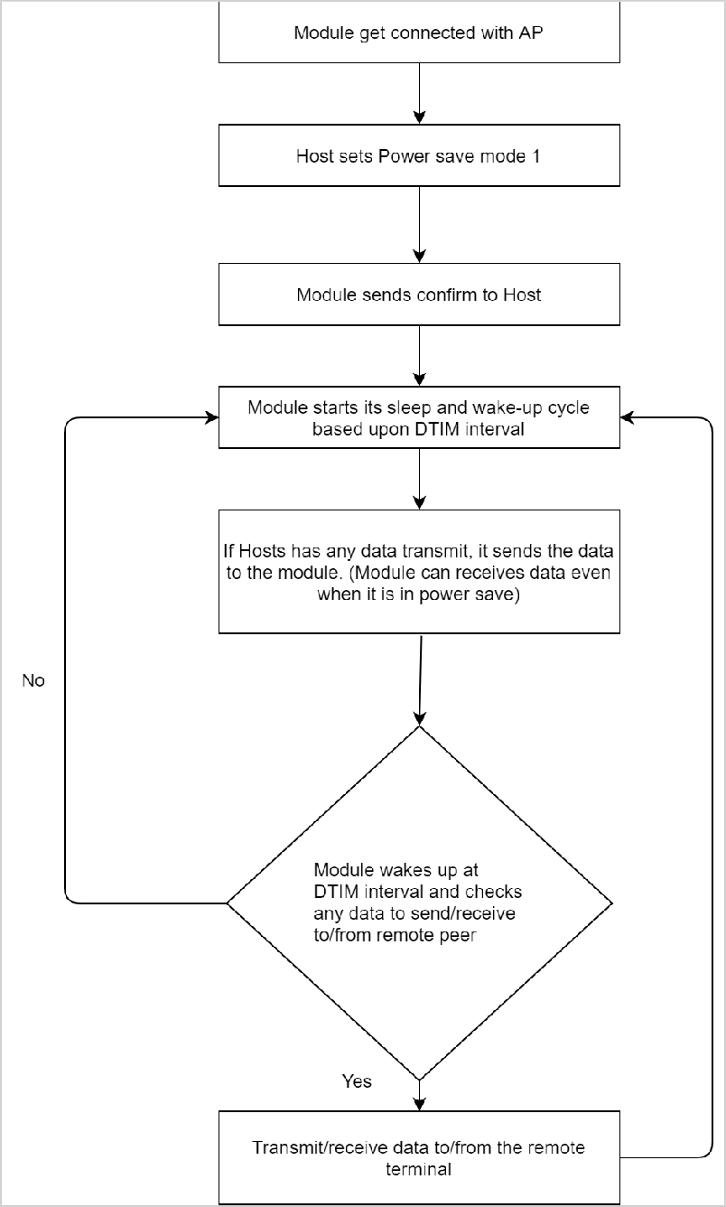
Powersave: Mode 1#
Once the module is configured in powersave mode 1, it wakes up periodically based upon the DTIM interval configured in the connected AP. In power mode 1, only the RF part of the module is in power save while SoC continues to work normally. This command has to be given only when the module is in the connected state (with the AP).
After configuring the module to powersave mode 1, the host can issue subsequent commands. In powersave mode 1, the module can receive data from the host at any point in time, but it can send/receive the data to/from the remote terminal (like a remote socket), only when it wakes up at DTIM interval.
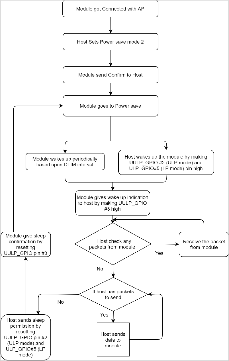
Powersave: Mode 2#
Once the module is configured in powersave mode 2, it can be woken up either by the host or periodically during its sleep-wake-up cycle based upon the DTIM interval. Power mode 2 uses GPIO based handshake.
In ULP mode, feature_bit_map[4] has to be set in opermode command.
In this mode, when the host wants to send data to the module, it sends a wakeup request to the module by asserting ULP_GPIO_5 high in the case of LP or UULP_GPIO_2 in case of ULP (which make the module wake up from powersave). After wakeup, if the module is ready for data transfer, it sends a wakeup indication to the host by asserting the UULP_GPIO_3 or UULP_GPIO_0.
The host is required to wait until the module gives the wakeup indication, before sending any data to the module. After completion of data, the host can give sleep permission to the module by de-asserting ULP_GPIO_5 in the case of LP or UULP_GPIO_2 in the case of ULP. After recognizing sleep permission from the host, the module confirms the host by de-asserting UULP_GPIO_3 or UULP_GPIO_0 and goes back to its sleep-wakeup cycle.
The module can send a received packet or response to the host at any point in time. No handshake is required on the receive path.
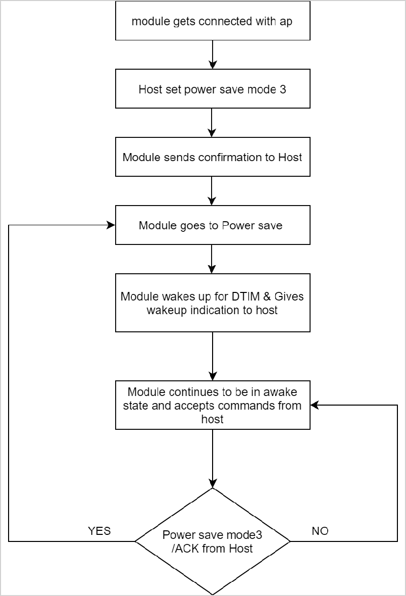
Powersave: Mode 3#
Powersave Mode 3 uses a Message-based handshake. In Powersave Mode 3, both radio and SoC of RS9116- WiSeConnect are in powersave.
This mode is significant when the module is connected to the AP. Module wakes up periodically every DTIM and sends a wakeup message ("WKP") to the host. The module cannot be woken up asynchronously.
Every time module intends to go to sleep it sends a sleep request message ("SLP") to the host and expects the host to send the ACK message ("ACK"). Host either sends an acknowledgment message ("ACK") or any other pending message. But once ACK is sent, the host should not send any other message until the next wakeup message from the module is received.
The module will not go into complete power save state if ACK is not received from the host for the sent sleep message ("SLP"). The module can send a received packet or response to the host at any point in time. No handshake is required on the receive path.
Powersave message | Source |
|---|---|
| from Module |
| from Module |
| from Host |
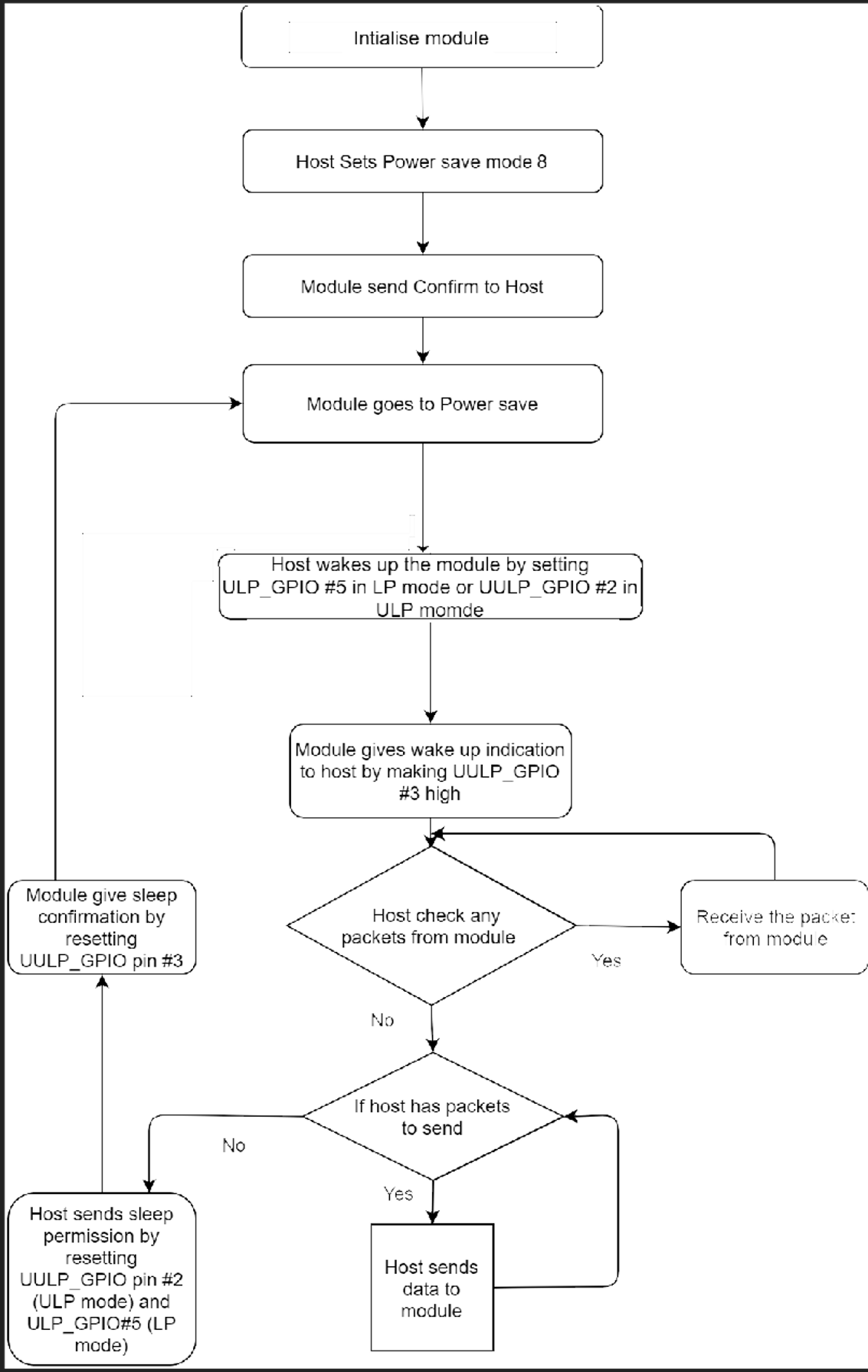
Powersave: Mode 8#
Powersave mode 8 uses GPIO based handshake. This command must be issued after the #init command. In Powersave Mode 8 both RF and SoC of RS9116-WiSeConnect are in complete powersave mode. This mode is significant when the module is not connected with any AP.
In ULP mode, feature_bit_map[4] has to be set in opermode command. In the case of LP (when ulp_mode_enable is 0) host can wake up the module from power save by asserting ULP_GPIO_5. In the case of ULP (when ulp_mode_enable is 1 or 2) host can wake up the module from power save by asserting UULP_GPIO_2.
When ulp_mode_enable is set to 0 or 1, once the module gets a wake-up request from the host, DUT wakes up and indicates it is awake by asserting UULP_GPIO_3 or UULP_GPIO_0 based on the Wakeup indication GPIO selection in opermode command. The host is required to wait until the module gives the wakeup indication, before sending any next command to the module. After completion of command/data, the host can give sleep permission to the module by de-asserting ULP_GPIO_5 in the case of LP or UULP_GPIO_2 in the case of ULP. After recognizing sleep permission from the host, the module confirms the host by de-asserting UULP_GPIO_3 or UULP_GPIO_0 and goes back to its sleep-wakeup cycle.
The module can send a received packet or response to the host at any point in time. No handshake is required on the receive path.
When ulp_mode_enable is set to 2, after the module wakes up from sleep, the host needs to start giving commands from the beginning(opermode) as the module's state is not retained.
Note!
By default UULP_GPIO_3 is used for wakeup indication to host. If config_feature_bit_map[0] = 1 then UULP_GPIO_0 is used for wakeup indication to host.
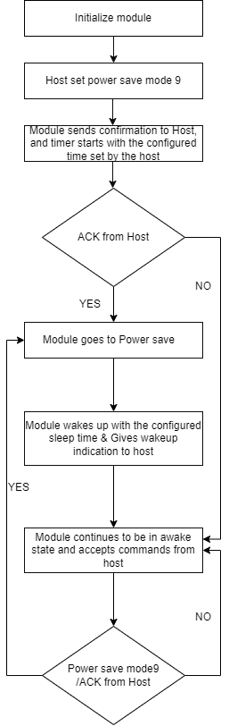
Powersave: Mode 9#
Powersave Mode 9 uses a Message-based handshake. In this mode, the entire module, including the radio, enters powersave mode. This mode is significant when the module is not connected with any AP.
After receiving a powersave mode 9 command, the module sends SLP (Sleep) request to the host and waits for an ACK from the host. After the ACK (Acknowledgement) is received, the module goes to sleep. The sleep timer starts when powersave command is received. It can be configured by the host using the at+rsi_sleeptimer command.
If the host does not set any sleep time, the timer is configured for 3 seconds by default. Upon wakeup, the module sends a wakeup message to the host and expects the host to send an ack before it goes into the next sleep cycle. The host either sends an ACK or a message. However, once an ACK is sent, no other packet should be sent before receiving the next wakeup message.
Powersave message | Source |
|---|---|
| from Module |
| from Module |
| from Host |
When ulp_mode_enable is set to 2, after waking up from sleep, the module sends the wakeup from sleep message (WKP FRM SLEEP) to the host when RAM retention is not enabled. After receiving the message, the host needs to start giving commands from the beginning (opermode) as the module's state is not retained.
Powersave message | Source |
|---|---|
| from Module |
Note!
Sleep Timer starts when SLP request is sent to the host. Sleep time varies based on the ACK sent by the host. If the ACK sent by the host is delayed, Module will be in sleep state for the remaining time.
[ Go to top ]
rsi_psk :: Wi-Fi Pre-shared Key
Description#
The command is used to set the PSK (Pre shared key) to join to WPA/WPA2-PSK enabled APs. Using this command user can also pass the PMK (PAIRWISE MASTER KEY) as a parameter and can also generate PMK by providing PSK and SSID of connecting AP.
User can directly give PMK from host to reduce the connection time. This command should be issued after init and before join command, if module needs to connect to an secure Access point. This command can be ignored if the AP is in Open mode.
Command Format#
Standard PSK Format
at+rsi_psk=<psk_type>,<psk_or_pmk>,<ap_ssid>Length-based PSK Format enables a comma in the PSK
at+rsi_psk=<psk_type>,<length_of_psk>,<psk_or_pmk>,<ap_ssid>Parameters#
psk_type (1 byte)
1-pre_shared_keyis provided inpsk_or_pmkfield2-pairwise_master_keyis provided inpsk_or_pmk field3- generate pairwise master key from given pre shared key and SSID to which module wants to connect.4- length based PSK5- generation of PMK from length based PSK and SSID
length_of_psk (1 byte)
Length of PSK which can include a comma
It is mandatory that the PSK length in the command is equal to length_of_psk. Inconsistent values may lead to undefined behavior.
psk_or_pmk (64 bytes)
In this field expected parameters are pre shared key of the access point to which module wants to associate or pair wise master key. Length of this field is 64 Bytes. In case of PMK only 32 bytes are valid, In case of PSK length can vary (8 to 63).
The PMK is 32 bytes in hex format (64 characters). The following example shows the PMK as an array.
PMK[32] = {0x71, 0x72, 0x01, 0x0A, 0x16, 0x17, 0x07,0x90, 0x71, 0x72, 0x01, 0x0A, 0x16, 0x17, 0x07,0x90, 0x71, 0x72, 0x01, 0x0A, 0x16, 0x17, 0x07,0x90, 0x71, 0x72, 0x01, 0x0A, 0x16, 0x17, 0x07, 0x90};The command using this PMK is
at+rsi_psk=2,7172010A161707907172010A161707907172010A161707907172010A16170790ap_ssid (34 bytes)
This field contains the SSID of the access point, this field will be valid only if
psk_typevalue is3.The maximum length of SSID is 32 bytes and the remaining 2 bytes are reserved for NULL termination and alignment.
If user generates PMK using
psk_type = 3 or 5(i.e., by providing psk and ssid) then module uses generated PMK for connection establishment and there is no need to give pre-shared key or pair wise master key again.
Response#
Response contains following payload only if psk_type = 3or 5. In case of psk_type = 1 or 2, response does not contain any payload.
Result Code | Description |
|---|---|
OK | Success. If TYPE value is |
| Success. If TYPE value is |
| Failure |
Pair wise master key of 32-bytes is given to host if psk_type is 3 or 5.
Possible error codes for this command are 0x0021, 0x0025, 0x0026, 0x0028, 0x002C, 0x0039, 0x003a, 0x003b.
Availability#
This command is available in operating mode 0 and 9.
Example 1#
To join a WPA2-PSK security enabled network with key "12345ABCDE", the command is
Command
at+rsi_psk=1,12345ABCDE
0x61 0x740x2B0x720x730x690x5F 0x70 0x73 0x6B 0x3D 0x31 0x2c 0x31 0x32 0x33 0x34 0x35 0x41 0x42 0x43 0x44 0x45 0x0D 0x0AResponse
OK
0x4F 0x4B 0x0D 0x0AExample 2#
To join a WPA2-PSK security enable network with pairwise_master_key "ABCDEFABCDEFABCDEF12345678901234ABCDEFABCDEFABCDEF12345678901234",the command is:
Command
at+rsi_psk=2,ABCDEFABCDEFABCDEF12345678901234ABCDEFABCDEFABCDEF12345678901234Response
OK
0x4F 0x4B 0x0D 0x0AExample 3#
To generate pairwise_master_key for the pre_shared_key = 12345678 and SSID MY_NETWORK_NAME, the command is
Command
at+rsi_psk=3,12345678,MY_NETWORK_NAMEResponse
OK <pairwise_master_key>
0x4F 0x4B <32bytes of pairwise_master_key> 0x0D 0x0A[ Go to top ]
rsi_wepkey :: Set WEP Keys#
Description#
This command configures the WEP key in the module to connect to an AP with WEP security. This command should be issued before join.
Command Format#
at+rsi_wepkey=<index>,<key1>,<key2>,<key3>,<key4>Parameters#
index (2 bytes)
Selects key index configured in AP
0 - Key 1 is used
1 - Key 2 is used
2 - Key 3 is used
3 - Key 4 is used
keyX
key1,key2,key3,key4are the WEP keys. The module supports WEP hex mode only.The WEP key supplied to the AP should be of 10 characters (for 64 bit WEP mode) or 26 characters (for 128 bit WEP mode), and only the following characters are allowed for the key:
A,B,C,D,E,Fa,b,c,d,e,f0,1,2,3,4,5,6,7,8,9
Response#
Result Code | Description |
|---|---|
| Success |
| Failure |
Possible error codes are 0x0021, 0x0025, 0x002C, 0x002D
Availability#
This command is available when the module is configured in Operating Mode 0.
Example#
Provide 4 WEP keys:
Command
at+rsi_wepkey=0,ABCDE12345,ABCDE12346,ABCDE12347, ABCDE12348Provide one WEP key:
Command
at+rsi_wepkey=0,ABCDE12345,0,0,0
at+rsi_wepkey=2,0,0,ABCDE12345,0Response
OK
0x4F 0x4B 0x0D 0x0A[ Go to top ]
rsi_authmode :: WEP Authentication Mode#
Description#
This command configures the authentication mode for WEP in the module, if the AP is in WEP security mode.
Command Format#
at+rsi_authmode=<auth_mode>Parameters#
auth_mode
Set to
0for open WEP authentication. WEP shared mode is NOT supported.
Response#
Result Code | Description |
|---|---|
| Success |
| Failure, |
Possible error codes are 0x0021, 0x0025, 0x002C, 0xFFF8, 0x002D
Availability#
This command is available when the module is configured in Operating Mode 0
Example#
Command
at+rsi_authmode=0
0x61 0x74 0x2B0x72 0x73 0x69 0x5F 0x61 0x75 0x74 0x68 0x6D 0x6F 0x64 0x65 0x3D 0x30 0x0D 0x0AResponse
OK
0x4F 0x4B 0x0D 0x0A[ Go to top ]
rsi_eap :: EAP Configuration#
Description#
This command is used to configure the EAP parameters for connecting to an Enterprise Security enabled Access Point. The supported EAP types are EAP-TLS, EAP-TTLS, EAP-PEAP, EAP-FAST and EAP-LEAP. EAP-GTC is not supported for EAP-FAST. This command can be sent any time after rsi_init and rsi_join in enterprise security mode.
Command Format#
at+rsi_eap =<eap_method>,<inner_method>,<user_identity>,<password>,<okc>,<private_key_password>Parameters#
eap_method (32 bytes)
Selects EAP method: TLS, TTLS, FAST, PEAP or LEAP. It should be ASCII character string.
inner_method (32 bytes)
This field is valid only in TTLS/PEAP. In case of TTLS/PEAP supported inner methods are MSCHAP/MSCHAPV2. In case of TLS/FAST/LEAP this field is not valid and it should be fixed to MSCHAPV2.
Here MSCHAP/MSCHAPV2 are ASCII character strings.
user_identity (64 bytes)
User ID which is configured in the user configuration file of the radius sever.
password (128 bytes)
Password which is configured in the user configuration file of the Radius Server for that User Identity.
okc (4 bytes)
This argument is used to enable or disable or select multiple features from user. Below is the detailed description of this argument.
BIT[0] of OKC is used to enable or disable opportunistic key caching (OKC),
0– disable1– enableWhen this is enabled, module will use cached PMKID to get MSK(Master Session Key) which is need for generating PMK which is needed for 4-way handshake.
BIT[1] of OKC is used to enable or disable CA certificate requirement for PEAP connection.
0– CA certificate is not required.1– CA certificate is required.
BIT[2-12] of OKC argument are used for Cipher list selection for EAP connection. All possible ciphers are listed below
Cipher's List#
BIT position | Cipher selected |
|---|---|
| DHE-RSA-AES256-SHA256 |
| DHE-RSA-AES128-SHA256 |
| DHE-RSA-AES256-SHA |
| DHE-RSA-AES128-SHA |
| AES256-SHA256 |
| AES128-SHA256 |
| AES256-SHA |
| AES128-SHA |
| RC4-SHA |
| DES-CBC3-SHA |
| RC4-MD5 |
BIT[13-31] of OKC argument is reserved.
Note!
When user sets BIT[1] and does not provide the CA certificate then error is thrown. If user provides invalid CA certificate then also error is thrown.
User can set either one or multiple bits from BIT[2-12] to provide the cipher's list.
When user does not provide any value in OKC's BIT[2-12] then by default all the ciphers are selected.
private_key_password (82 bytes)
This is password for encrypted private key given to the module. Module will use this password during decryption of encrypted private key. password length must be 80 bytes or less.
Response#
Result Code | Description |
|---|---|
| Success |
| Failure |
Possible error codes are 0x0021, 0x0025, 0x002C
Availability#
This command is available when the module is configured in Operating Mode 2.
Example#
Command
at+rsi_eap=PEAP,MSCHAPV2,user1,12345678,0
0x61 0x74 0x2B 0x72 0x73 0x69 0x5F 0x65 0x61 0x70 0x3D 0x50 0x45 0x41 0x50 0x2C 0x4D 0x53 0x43 0x48 0x41 0x50 0x56 0x32 0x2C 0x75 0x73 0x65 0x72 0x31 0x2C 0x31 0x32 0x33 0x34 0x35 0x36 0x37 0x38 0x2C 0x30 0x0D 0x0ASee the AT Command Example reference for additional examples.
Response
OK
0x4F 0x4B 0x0D 0x0A[ Go to top ]
rsi_cert :: Set TLS Certificate#
Description#
This command is used to load/erase SSL/TLS (certificate and private keys) and enterprise security (EAP-TLS or EAP-FAST) certificates. Certificates should be loaded before using SSL/EAP. This command should be sent before join command for enterprise security mode and before socket creation for SSL sockets. Certificates will be loaded in non-volatile memory of the module, so that loading certificate is required to be done only once.
Note!
Enable powersave before loading certificates if the module is in Wi-Fi connected state.
Need to shut down the SSL socket for which it wants to change the certificates, if the socket is already in the connected state, otherwise, the firmware will throw an error.
Command Format#
at+rsi_cert =<cert_type>,<total_len>,<key_pwd>,<certificate>Parameters#
cert_type (1 byte)
cert_type | Type of certificate |
|---|---|
1 | EAP client certificate |
2 | FAST PAC file |
3 | SSL Client Certificate |
4 | SSL Client Private Key |
5 | SSL CA Certificate |
6 | SSL Server Certificate |
7 | SSL Server Private Key |
17 | EAP private key |
33 | EAP public key |
49 | EAP CA certificate |
total_len (2 bytes)
Certificate's total length in bytes.
Note!
For Enterprise security, maximum certificate length should be 12280 bytes. For TLS Certificates, the max length is 12280 bytes and for the Private Keys, it is 4088 bytes.
Module shares same TLS certificates for all supported SSL sockets.
For enterprise, user can load certificates in two ways
User can provide wifiuser.pem which contains 4 certificates in a given fixed order of private key, client certificate 1, client certificate 2, CA certificate with CertType as 1.
User can load individual EAP certificates private key, public key, and CA certificates with CertType as 17,33 and 49 respectively. Maximum certificate length for each individual certificates is 4088 bytes
Certificate Loading into Flash is only allowed upto init state. After init state e.g. scan/join etc certificate loading into flash is not allowed.
Certificate Loading into RAM is allowed in connected state also provided same type of socket already does not exist. For example, loading client cert is only allowed if there does not exist any client socket. Same is for server certificates too
Root certificate has the highest authority being at the top of the signing hierarchy.
Root certificate is an expected/required certificate which usually comes pre-installed in the operating systems and it plays a key part in certificate chain verification when a device is performing TLS authentication with the IoT endpoint.
On RS9116 device, we do not maintain root trust repository due to memory constraints, so it is mandatory to load Root certificate for successful mutual authentication.
On RS9116 to authenticate, firstly Root CA is validated (validate the Root CA received with the Root CA loaded on the device). Once the Root CA is validation is successful , other certificates sent from the server are validated.
RS9116 will not be able to authenticate to server if intermediate CA certificates are loaded instead of Root CA and would result in Handshake error.
The valid certificate format to load into the module is .pem. It is recommended to use loading of single certificate method (wifiuser.pem)
By default, TLS certificates will be loaded onto flash. Set
BIT(27)intcp_ip_feature_bit_mapto load TLS certificate onto RAM.
key_pwd(128 bytes)
Reserved.
certificate
This is the data of the actual certificate.
To erase a certificate, set
total_len,key_pwd,certificatefields '0'.cert_typeshould be set to type of the certificate to erase as mentioned above. See the following example.
at+rsi_cert=<cert_type>,0,0,0Response#
Result Code | Description |
|---|---|
| Success |
| Failure |
Possible error codes are 0x0015, 0x0021, 0x0025, 0x0026, 0x002C
Availability#
This command is available when the module is configured in Operating Mode 0,2
Example#
The following example shows the procedure for loading certificates using Python on a PC. Requirements: Python 2.7.10 and pyserial
It may not be possible to issue this command in Hyper-terminal because the content of a certificate file needs to be supplied as one of the inputs of the command. This can be done by other means, such as using a Python script.
Loading or erasing the certificates should be performed only after the opermode command has been issued.
Before loading the certificate, certificates should be erase the certificate.
To load the certificate, run the python script
load_certificate.pyavailable in the WiSeConnect SDK utilities folder
Copy
load_certificate.pyto...\resouces\certificatesfolder in the SDK.Ensure the serial port and baudrate of the hardware e.g. sp=serial.Serial(port="COMx",baudrate=115200,timeout=0.01))
Run the python scripts using ->
python load_certificate.py <CertType> <Certificate>After successful certificate loading, the script respondes with
OK
Command
at+rsi_cert=1,0,0,0
0x61 0x74 0x2B 0x72 0x73 0x69 0x5F 0x63 0x65 0x72 0x74 0x3D 0x31 0x2C 0x30 0x2C 0x30 0x2C 0x30 0x0D 0x0AResponse
OK
0x4F 0x4B 0x0D 0x0A[ Go to top ]
rsi_cert_index :: Set Certificate With Index#
Description#
This command is used to load/erase SSL (certificate and private keys). Certificates should be loaded before using TLS. This command should be sent before socket creation for TLS sockets. Certificates will be loaded in non-volatile memory of the module, so that loading certificate is required to be done only once.
Note!
This command is used for standalone Wi-Fi mode in case of loading certificates for multiple TLS sockets to flash.
This command should be sent only after
opermodecommand.
Command Format#
at+rsi_cert_index =<cert_type>,<total_len>,<cert_index>,<key_pwd>,<certificate>Parameters#
cert_type (1 byte)
| Type of certificate |
|---|---|
1 | EAP Client certificate |
2 | FAST PAC file |
3 | SSL Client Certificate |
4 | SSL Client Private Key |
5 | SSL CA Certificate |
6 | SSL Server Certificate |
7 | SSL Server Private Key |
17 | EAP private key |
33 | EAP public key |
49 | EAP CA certificate |
total_len (2 bytes)
Certificate's total length in bytes.
Note!
For TLS certificates, the max length is 12280 bytes and for the Private Keys, it is 4088 bytes.
Recommended to use loading of single certificate method (wifiuser.pem)
Set
BIT[27]intcp_ip_feature_bit_mapto load TLS certificate onto RAM. By default SSL certificates will be loaded onto flash.Set
BIT[31]intcp_ip_feature_bit_map&BIT[29]inext_tcp_ip_feature_bit_mapto open 3 SSL Client sockets.
cert_index (1 byte)#
RS9116 can either load certificates onto RAM or FLASH, but not both at a time.
Module can hold two sets of TLS certificate into RAM. This field is used to provide the index of the certificates and possible values are 0 and 1.
Module can hold three sets of TLS certificate onto Flash. This field is used to provide the index of the certificates and possible values are 0, 1 and 2.
key_pwd (127 bytes)
Reserved.
certificate
This is the data of the actual certificate.
To erase a certificate, set
total_len,key_pwd,certificatefields '0'.cert_typeshould be set to type of the certificate to erase as mentioned above. See the following example.
at+rsi_cert_index=<cert_type>,0<cert_index>,0,0.Response#
Result Code | Description |
|---|---|
| Success |
| Failure |
Possible error codes are 0x0015, 0x0021, 0x0025, 0x0026, 0x002C, 0x005D, 0x005E, 0x005F.
Availability#
This command is available when the module is configured in Operating Mode 0, 2.
Example#
The following example shows the procedure for loading certificates using Python on a PC. Requirements: Python 2.7.10 and pyserial
It may not be possible to issue this command in Hyper-terminal because the content of a certificate file needs to be supplied as one of the inputs of the command. This can be done by other means, such as using a Python script.
Loading or erasing the certificates should be performed only after the opermode command has been issued.
Before loading the certificate, certificates should be erase the certificate.
To load the certificate, run the python script
load_certificate.pyavailable in the WiSeConnect SDK utilities folder
Copy
load_certificate_with_inx.pyto '...\utilities\certificates' folder.User needs to ensure the serial port and baudrate of the hardware e.g. sp=serial.Serial(port="COMx",baudrate=115200,timeout=0.01)
Run the python scripts using ->
python load_certificate_with_inx.py <CertType><CertInx> <Certificate>After successful certificate loading,scripts give 'OK' as response.
After successful certificate loading,scripts give 'OK' as response.
For erasing certificate with index 0:
Command
at+rsi_cert_index=1,0,0,0,0
0x61 0x74 0x2B 0x72 0x73 0x69 0x5F 0x63 0x65 0x72 0x74 x5F 0x69 0x6E 0x78 0x3D 0x31 0x2C 0x30 0x2C 0x30 0x2C 0x30 0x2C 0x30 0x0D 0x0AResponse
OK
0x4F 0x4B 0x0D 0x0A[ Go to top ]
rsi_disassoc :: Wi-Fi Disassociate#
Description#
This command is issued to request the module to disassociate (disconnect) from an Access Point. The Host can then issue a fresh set of #init, #scan and #join commands to connect to a different Access Point or the same Access Point with a different set of connection parameters. This command can also be used to stop the module from continuing an on-going rejoin operation. Additionally, this command is used when the module is in AP mode, to remove clients from its list of connected nodes.
Command Format#
at+rsi_disassoc=<mode_flag>,<client_mac_addr>Parameters#
mode_flag (2 bytes)
Mode | Functionality |
|---|---|
0 | Module is in client mode. The second parameter mac_addr is ignored when mode is 0. |
1 | Module is in AP mode. |
client_mac_addr (6 bytes)
MAC address of the client to disconnect. Used when the module is in AP mode
Response#
Result Code | Description |
|---|---|
| Success |
| Failure |
Possible error codes are 0x0006, 0x0013, 0x0021, 0x002C, 0x0015.
Availability#
This command is available when the module is configured in Operating Mode 0, 2 and 6.
Note! After issuing disconnect command, any powersave enabled by that time will be disabled. User can reissue the powersave command after initializing the module again.
Example 1#
Module is in client mode and is connected to an AP. It wants to formally disconnect from the AP.
Command
at+rsi_disassoc=0
0x61 0x74 0x2B 0x72 0x73 0x69 0x5F 0x64 0x69 0x73 0x61 0x73 0x73 0x6F 0x63 0x3D 0x30 0x0D 0x0AExample 2#
Module is in AP mode and 3 clients are connected to it. One of the clients, with MAC 0x01 0x02 0x03 0x040 0x05 0x06, needs to be disconnected by the AP.
Command
at+rsi_disassoc=1,010203040506
0x61 0x740x2B0x720x730x690x5F 0x64 0x69 0x73 0x61 0x73 0x73 0x6F 0x63 0x3D 0x31 0x2C 0x30 0x31 0x30 0x32 0x30 0x33 0x30 0x34 0x30 0x35 0x30 0x36 0x0D 0x0AResponse
OK
0x4F 0x4B 0x0D 0x0A[ Go to top ]
rsi_ipconf :: Set IP Parameters#
Description#
This command configures the IP address, subnet mask and default gateway for the module.
Command Format#
at+rsi_ipconf=<dhcp_mode>,<ip_addr>,<netmask>,<gateway>,<hostname>,<vap_id>,<fqdn_flag>Parameters#
dhcp_mode (1 byte)
Used to configure TCP/IP stack in manual or DHCP modes.
0– Manual1– DHCP enabled3- Enable DHCP and to send host name in DHCP discover5- Enable Option 71 (Network News Server Addresses) with static IP.
Note!
DHCP Mode 5 is currently not supported.
In AP mode only DHCP manual mode (static IP) is valid. sending host name is valid only in DHCP enable mode.
4- To enable FQDN Option with static ip (Option 81 with static IP)7- To enable DHCP, hostname, DHCP Client FQDN option (Option 81: Fully Qualified Domain Name with Dynamic IP)9- To support DHCP unicast Offer from server
Module can obtain the DNS server IP address from DHCP offer, if the DHCP server supports it. However, the DNS server IP address it obtained is not accessible to the host.
ip_addr (4 bytes)
IP address in 4 bytes hex format. This can be 0's in case of DHCP.
netmask (4 bytes)
Subnet mask in 4 bytes hex format. This can be 0's in case of DHCP.
gateway (4 bytes)
Gateway in 4 bytes hex format. This can be 0's in case of DHCP.
hostname (31 bytes)
Host name for DHCP Client. This can be null, when DHCP mode is not enabled. This field is valid only when dhcp_mode value is 3. Maximum Hostname length is valid up to 31 bytes including NULL.
vap_id (1 byte)
Virtual Access Point (AP) is only relevant in concurrent mode and when dhcp mode is manual
0– Use to assign static IP for client mode.1- Use to start DHCP server in concurrent AP mode (should be given before AP creation i.e. join).
fqdn_flag (4 bytes)
0DNS Client should update TYPE_A (host name) record and TYPE_PTR records.1DHCP Server will update both TYPE_A and TYPE_PTR records
Response#
Result Code | Description |
|---|---|
| Success |
| Failure |
where ...
MAC_Address (6 bytes). MAC Address
IP_Address (4 bytes). Assigned IP address
Subnet_Mask (4 bytes). Assigned subnet address
Gateway (4 bytes). Assigned gateway address
Possible error codes are 0x0021, 0x0025, 0x002C, 0xFFFC, 0xFF74, 0xFF9C, 0xFF9D.
Availability#
This command is available when the module is configured in Operating Mode 0, 2, 6 and 9.
Example 1#
To configure in manual mode, with
192.168.1.3as IP address255.255.255.0as subnet mask192.168.1.1as the gateway
Command
at+rsi_ipconf=0,192.168.1.3,255.255.255.0,192.168.1.1
0x61 0x74 0x2B 0x72 0x73 0x69 0x5F 0x69 0x70 0x63
0x6F 0x6E 0x66 0x3D 0x30 0x2C 0x31 0x39 0x32 0x2E
0x31 0x36 0x38 0x2E 0x31 0x2E 0x33 0x2C 0x32 0x35
0x35 0x2E 0x32 0x35 0x35 0x2E 0x32 0x35 0x35 0x2E
0x30 0x2C 0x31 0x39 0x32 0x2E 0x31 0x36 0x38 0x2E
0x31 0x2E 0x31 0x0D 0x0AResponse
OK <MAC_Address><IP_Address><Subnet_Mask><Gateway>
0x4F 0x4B 0x01 0x02 0x03 0x04 0x05 0x06 0xC0 0xA8 0x01 0x03 0xFF 0xFF 0xFF 0x00 0xC0 0xA8 0x01 0x01 0x0D0x0AExample 2#
To configure the IP in DHCP enabled mode.
Command
at+rsi_ipconf=1,0,0,0
0x61 0x74 0x2B 0x72 0x73 0x69 0x5F 0x69 0x70 0x63 0x6F 0x6E 0x66 0x3D 0x31 0x2C 0x30 0x2C 0x30 0x2C 0x30 0x0D 0x0AResponse
OK <MAC_Address><IP_Address><Subnet_Mask><Gateway>
0x4F 0x4B 0x01 0x02 0x03 0x04 0x05 0x06 0xC0 0xA8 0x01 0x03 0xFF0xFF0xFF0x000xC00xA80x010x01 0x0D 0x0AExample 3#
To configure the IP in DHCP enabled mode with hostname.
Command
at+rsi_ipconf=3,dhcp_client
0x61 0x74 0x2B 0x72 0x73 0x69 0x5F 0x69 0x70 0x63 0x6F 0x6E 0x66 0x3D 0x31 0x2C 0x30 0x2C 0x30 0x2C 0x30 0x0D 0x0AResponse
OK <MAC_Address><IP_Address><Subnet_Mask><Gateway>
0x4F 0x4B 0x01 0x02 0x03 0x04 0x05 0x06 0xC0 0xA8 0x01 0x03 0xFF0xFF0xFF0x000xC00xA80x01 0x01 0x0D 0x0A[ Go to top ]
rsi_ipconf6 :: Set IPv6 Parameters#
Description#
This command configures the IPv6 address, prefix length and default router for the module.
Command Format#
at+rsi_ipconf6=<mode>,<prefix_length>,<ip_addr_6>,<gateway_6>\r\nParameters#
mode (1 byte)
Used to configure TCP/IP stack in manual or DHCPv6 modes.
Static
DHCPv6/SLAAC (depends on Router Advertisement message)
prefix_length (2 bytes)
Prefix length of the IPv6 address.
ip_addr_6 (16 bytes)
IPv6 address. This can be 0's in the case of DHCPv6.
gateway_6 (16 bytes)
Default router's IPv6 address. This should be Null in the case of DHCPv6.
IPV6 address is generally of the form - octet of four hexadecimal digits separated by "colons". e.g. 2001:0db8:1:0:0:0:0:123 (supported format) 2001:db8:1::123 (not supported format)
Double colons are used in place of continuous zeroes in IPV6 address, to minimize the IPV6 address, but in RS9116-WiSeConnect double colons are not supported. In ipconf6 command you have to supply all the eight groups of four hexadecimal digits.
Response#
Result Code | Description |
|---|---|
| Successful execution of the command |
| Failure |
Response Parameters#
prefix_length (2 bytes). Prefix length of IPv6 address
reserved (2 bytes). Reserved bits
link_local_address (16 bytes). Local address
ip_addr_6 (16 bytes). Assigned IPv6 address
default_gw_6 (16 bytes). Assigned default router address
Possible error codes are 0x0021, 0x0025, 0x002C, 0xFFFC, 0xFF74, 0xFF9C, 0xFF9D.
Availability#
This command is available when the module is configured in Operating Mode 0, 2 and 6.
Example 1#
To configure in static mode, with 2001:db8:1:0:0:0:0:123 as the IPV6 address and with 2001:db8:1:0:0:0:0:100 as router IPV6 address. Command
at+rsi_ipconf6=0,64,2001:DB8:1:0:0:0:0:123,2001:DB8:1:0:0:0:0:100\r\n
0x61 0x74 0x2B 0x72 0x73 0x69 0x5F 0x69 0x70 0x63 0x6F 0x6E 0x66 0x36 0x3D 0x30 0x2C 0x36 0x34 0x2C 0x32 0x30 0x30 0x31 0x3A 0x44 0x42 0x38 0x3A 0x31 0x3A 0x30 0x3A 0x30 0x3A 0x30 0x3A 0x30 0x3A 0x31 0x32 0x33 0x2C 0x32 0x30 0x30 0x31 0x3A 0x44 0x42 0x38 0x3A 0x31 0x3A 0x30 0x3A 0x30 0x3A 0x30 0x3A 0x30 0x3A 0x31 0x30 0x30 0x0D 0x0AResponse
OK <prefix_length><reserved><link_local_address><ip_addr6><gateway6>\r\n
0x4F 0x4B 0x40 0x00 0x00 0x00 0x01 0x06 0x04 0x0A 0x0C 0xCE 0x01 0x00 0x00 0x00 0x80 0xFE 0x00 0x00 0x00 0x00 0xB8 0x0D 0x01 0x20 0x00 0x00 0x01 0x00 0x00 0x00 0x00 0x00 0x23 0x01 0x00 0x00 0xB8 0x0D 0x01 0x20 0x00 0x00 0x01 0x00 0x00 0x00 0x00 0x00 0x00 0x01 0x00 0x00 0x0D 0x0AExample 2#
To configure the IPV6 in DHCPV6 enabled mode.
Command
at+rsi_ipconf6=1,0,0,0\r\n
0x61 0x74 0x2B 0x72 0x73 0x69 0x5F 0x69 0x70 0x63 0x6F 0x6E 0x66 0x36 0x3D 0x31 0x2C 0x30 0x2C 0x30 0x2C 0x30 0x0D 0x0AResponse
OK<prefix_length><reserved><link_local_address><ip_addr_6><gateway_6>\r\n
0x4F 0x4B 0x40 0x00 0x00 0x00 0x00 0x00 0x80 0xFE 0x00 0x00 0x00 0x00 0xFF 0x55 0xC9 0x82 0xB4 0xF9 0x34 0xFE 0x90 0x42 0x01 0x24 0xED 0x10 0x89 0x12 0x00 0x00 0x00 0x00 0x05 0x01 0x00 0x00 0x00 0x00 0x80 0xFE 0x00 0x00 0x00 0x00 0xFF 0xF5 0x0F 0x52 0xF0 0xBB 0x2F 0xFE 0x0D 0x0A[ Go to top ]
RSI_IPCONF :: IP Change Notification#
Description#
This notification is received when module gets a different IP compared to modules old IP address, after DHCP renewal. Module indicates this IP change to host by an asynchronous frame.
Notification Format#
AT+RSI_IPCONF<mac_addr><ip_addr><netmask><gateway>where ...
mac_addr (6 bytes)
MAC Address ip_addr(4 bytes) Assigned IP address
netmask (4 bytes)
Assigned subnet address
gateway (4 bytes)
Assigned gateway address
Availability#
This command is available when the module is configured in Operating Mode 0, 2 and 6.
Example#
Command
at+rsi_ipconf<macAddr><ip_addr><netmask><gateway>
0x41 0x54 0x2B 0x52 0x53 0x49 0x5F 0x49 0x50 0x43 0x4F 0x4E 0x46 0x3D 0x01 0x02 0x03 0x04 0x05 0x06 0xC0 0xA8 0x01 0x03 0xFF 0xFF 0xFF 0x00 0xC0 0xA8 0x01 0x01 0x0D 0x0A[ Go to top ]
rsi_tcp :: Open a Socket#
Description#
This command is used to establish either a client or server socket.
Note!
A maximum of 10 sockets can be opened. Range of socket handles are between 1 to 10.
Module supports maximum of 2 TLS sockets. These can be either client or server sockets. When HTTPS server is enabled then user can open only 1 TLS socket.
Module supports maximum of 8 non TLS Web sockets and 2 TLS Web sockets.
After MQTT connection, the maximum LTCP can support is only 9.
Each TLS/Web socket will occupy one TCP socket. TLS is supported only in Wi-Fi Client mode
If TLS is enabled, module uses same TLS version until module reboots.
If TLS is enabled, the module uses the same CA certificate for both TLS server socket and TLS Client socket until module reboots.
If the destination IP address is given as 0.0.0.0, the module will try to read the server IP and port number from the flash using port number passed in the command as the index number. The index number should be same as the index number value used while storing the server IP and port number. Index number range is 0 to 3. In this case, all other commands processed normally.
Case 7 is valid only when BIT(27) is not set in tcp_ip_feature_bit_map (module will use TLS certificates from FLASH).
If BIT(27) (TLS certificate on to the RAM feature) is set in tcp_ip_feature_bit_map, module only supports either TLS server socket or TLS Client socket.
Command Format#
UDP Client (IPv4)#
at+rsi_udp=<dest_ip_addr>,<dest_port>,<local_port>,<tos>,<socket_bitmap>,<vap_id>UDP Server (IPv4)#
at+rsi_ludp=<local_port>,<tos>,<socket_bitmap>,<vap_id>TCP/TLS/Web Client (IPv4)#
at+rsi_tcp=<dest_ip_addr>,<dest_port>,<local_port>,<tos>,<tls_ws_enable>,<tls_ciphers_bitmap>,<webs_resource_name>, <webs_host_name>,<tcp_retry_count>,<socket_bitmap>,<rx_window_size>,<tcp_keepalive_timeout>,<vap_id>,<cert_index>,<use_fqdn_resolved_ip>TCP/TLS/Web Server (IPv4)#
at+rsi_ltcp=<local_port>,<max_count>,<tos>,<tls_ws_enable>,<tls_ciphers_bitmap>,<tcp_retry_count>,<socket_bitmap>,<rx_window_size>,<tcp_keepalive_timeout>,<vap_id>,<cert_index>Note!
When using TCP sockets, it is recommended to set ext_tcp_ip_feature_bit_map[16] when configuring the operating mode using the command: rsi_opermode.
If Destination IP address format is invalid and "destination port, source port and tos" are not in the range mentioned, then 0xFFF8 error will be indicated to Host.
Parameters#
dest_ip_addr
IP Address
dest_ip_addr (4 bytes)
IPv4 address if
ip_version 4is selected. Module ignores remaining 12 bytes in case of ip version 4.
local_port (2 bytes)
Local port number used by the module for the socket. Value ranges from
[1024 .. 49151]
dest_port (2 bytes)
Destination port. Value ranges from
[1024 .. 49151]EXCEPT30000which is reserved. Ignored when TCP server or listening UDP sockets are to be opened.
max_count (2 bytes)
Maximum number of clients which can be connected in case of LTCP.
Note!
Module supports maximum two TLS sockets, so max_count should be less than or equal to 2 when a listening TCP server (LTCP) is used. If max_count is 2 then host can create only one TLS based LTCP socket with two clients support.
This field max_count can be ignored if the socket type is other than 2 (TCP server).
tos (4 bytes)
Type of Service field. Possible values are
[0 .. 7]
TOS Value | Description |
|---|---|
0 | Best Effort |
1 | Priority |
2 | Immediate |
3 | Flash-mainly used for voice signaling |
4 | Flash Override |
5 | Critical - mainly used for voice RTP (Real-time Tranlocal_port Protocol) |
6 | Internet |
7 | Network |
tls_ws_enable (1 byte)
This field is used to enable the following socket combinations
0x00– Open TCP socket0x01- Open SSL Client socket0x02- Open Web socket client0x04- Open SSL socket with TLS 1.0 version0x08- Open SSL socket with TLS 1.2 version0x80- Open High performance TCP Rx socket
Note!
To support TLS sockets with multiple TLS Versions, set ext_custom_feature_bitmap[14] = 1
Example combinations are listed below.
0x00to open normal TCP socket0x01to open SSL over TCP socket. By default module will open TLS socket that supports both TLS 1.0 and TLS 1.2.0x02to open web socket client over TCP socket0x03to open web socket over SSL TCP socket0x05to open SSL over TCP socket with TLS 1.0 version0x09to open SSL over TCP socket with TLS 1.2 version0x07to open web socket client over SSL TCP socket with TLS 1.0 version0x0Bto open web socket client over SSL TCP socket with TLS 1.2 version0x80to open High performance TCP socket0x81to open High performance TCP socket over SSL0x82to open High performance Web socket0x83to open High performance Web socket over SSL
tls_ciphers_bitmap (4 bytes)
The default set of ciphers that are always available is listed below.
TLS_ECDHE_ECDSA_WITH_3DES_EDE_CBE_SHATLS_ECDHE_RSA_WITH_3DES_EDE_CBC_SHATLS_DHE_RSA_WITH_3DES_EDE_CBC_SHATLS_ECDHE_ECDSA_WITH_AES_256_CBC_SHATLS_DHE_RSA_WITH_AES_128_CBC_SHATLS_DHE_RSA_WITH_AES_256_CBC_SHATLS_ECDHE_RSA_WITH_AES_128_CBC_SHATLS_ECDHE_RSA_WITH_AES_256_CBC_SHATLS_ECDHE_ECDSA_WITH_AES_128_CBC_SHA256TLS_ECDHE_ECDSA_WITH_AES_256_CBC_SHA384TLS_ECDHE_RSA_WITH_AES_128_CBC_SHA256TLS_ECDHE_RSA_WITH_AES_256_CBC_SHA384TLS_DHE_RSA_WITH_AES_128_CBC_SHA256TLS_DHE_RSA_WITH_AES_256_CBC_SHA256
tls_ciphers_bitmap[31]is used to select between a basic set of additional ciphers or an extended set of ciphers.When
tls_ciphers_bitmap[31] = 0, the following ciphers are available according to whether the corresponding bit is set.
Bit Position | Value | Name |
|---|---|---|
|
|
|
|
|
|
|
|
|
|
|
|
|
|
|
|
|
|
When
tls_ciphers_bitmap[31] = 1, the following extended set of ciphers is available according to whether the corresponding bit is set.
Bit Position | Macro | Set to 0 | Set to 1 |
|---|---|---|---|
|
| Disable | Enable |
|
| Disable | Enable |
|
| Disable | Enable |
|
| Disable | Enable |
|
| Disable | Enable |
|
| Disable | Enable |
| Reserved | ||
| Reserved | ||
|
| Disable | Enable |
|
| Disable | Enable |
|
| Disable | Enable |
|
| Disable | Enable |
| Reserved | ||
| Reserved | ||
|
| Disable | Enable |
|
| Disable | Enable |
|
| Disable | Enable |
|
| Disable | Enable |
|
| Disable | Enable |
|
| Disable | Enable |
|
| Disable | Enable |
|
| Disable | Enable |
|
| Disable | Enable |
|
| Disable | Enable |
|
| Disable | Enable |
|
| Disable | Enable |
|
| Disable | Enable |
|
| Disable | Enable |
| Reserved | ||
| Reserved | ||
| Reserved | ||
|
| Disable | Enable |
Note! The RS9116 does not include hardware support for GCM based ciphers. Use of these ciphers may impact performance since related crypto operations are performed by software.
Index of the curve that may be used by TLS at the time of handshake
Curve Id | Description |
|---|---|
15 | secp160k1 |
16 | secp160r1 |
17 | secp160r2 |
18 | secp192k1 |
19 | secp192r1 |
20 | secp224k1 |
21 | secp224r1 |
22 | secp256k1 |
23 | secp256r1 |
24 | secp384r1 |
25 | secp521r1 |
26 | brainpoolP256r1 |
27 | brainpoolP384r1 |
28 | brainpoolP512r1 |
webs_resource_name (51 bytes)
The resource name to connect with at the websocket server. NULL is passed by default and the server assumes it as root. Examples:
/(default, the root of the server)/chat/sensor_pipe
A string of 50 characters plus null terminator is the maximum possible input to this variable.
webs_host_name (51 bytes)
Web socket hostname is the URL name of Websocket server to whom client will connect, by default NULL is passed and firmware sends it as localhost. Examples:
service.example.comsensors.mydomain.com
A string of 50 characters plus null terminator is the maximum possible input to this variable.
tcp_retry_count (1 byte)
Configure TCP retransmission count.
socket_bitmap (1 byte)
Configure socket bit map
socket_bitmap | Functionality | Description |
|---|---|---|
| Synchronous data read | Module sends data to host only after receiving data read request from host. |
| TCP socket | To open a listening TCP socket and to accept client connection, host need to provide accept command. |
| TCP ACK indication | When this bit is enabled module gives an TCP ACK indication (Frame type 0xAB) to host after receiving TCP ACK from remote peer.Host has to send next data packet to module only after receiving this TCP ACK indication |
| If this bit is set module handles small sized received packets effectively. | Recommended to set for the sockets which receive small size packets |
| TCP RX window size | When this bit is enabled, module opens socket with RX window size based on the value provided in rx_window_size field |
| Enable certificate indexing | When |
rx_window_size (1 byte)
This field is used to configure the RX window size for the TCP socket. Possible values are 1 to 15 based on the availability of memory.
tcp_keepalive_timeout (2 bytes)
This field is used to configure TCP keep alive initial timeout in seconds.
vap_id
Possible values are 0 and 1.
0– Module will try to connect to scanned AP.1– Module will create AP.
cert_index (1 byte)
Index for loading the certificate. Possible values: 0 and 1 for loading into RAM. Possible values: 0, 1, and 2 for loading into FLASH.
Note! Index-based certificate loading is valid only for storing certificates on to RAM or flash but not both at a time.
use_fqdn_resolved_ip (1 byte)
0- Disable the use of fqdn resolved ip address.1- Enable the use of fqdn resolved ip address.
Note!
If the user wishes to utilize the stored IP, they should input "0.0.0.0" as the ip_addr and set use_fqdn_resolved_ip to 1.
Response#
TCP/SSL/Web socket over IPv4#
Result Code | Description |
|---|---|
| Success. |
| Failure |
TCP/SSL server socket over IPv4 / LUDP socket over IPv4#
Result Code | Description |
|---|---|
| Success. |
| Failure |
where ...
ip_version(2 bytes) is the IP version used, either 4 or 6.socket_type(2 bytes) is Type of the created socket:0– TCP/SSL Client2– TCP/SSL Server (Listening TCP)4– Listening UDP
socket_descriptor(2 bytes). Created socket's descriptor or handle, starts from 1. socket_descriptor ranges from 1 to 10. The first socket opened will have a socket descriptor of 1, the second socket will have 2 and so on.local_port(2 bytes). Port number of the socket in the module.dest_port(2 bytes) Port number of the socket in the destination side.ip_addrIPv4 (4 bytes) IPv4 address if IPv4 is selected. Module ignores remaining 12 bytes in case of IPv4.
dest_ip_addrIPv4 (4 bytes) IPv4 address if IPv4 is selected. Module ignores remaining 12 bytes in case of ip version 4.
mss(2 bytes) maximum segment size of the remote peer. In case ofludp/ltcpthis field will not be present. - -window_size(4 bytes) Window size of the remote peer. In case ofludp/ltcpthis field will not be present.
Possible error codes are 0xBB46, 0xBB22, 0xBB23, 0xBB33, 0xBB34, 0xBB35, 0xBB36, 0xBB45, 0xBB46, 0x0015, 0x0021, 0x0025, 0x002C, 0xFF74, 0xBBD3, 0xBBD2, 0xBBD1, 0xFF80
Availability#
This command is available when the module is configured in Operating Mode 0, 2, 6 and 9.
Example 1#
Open TCP socket over IPv4
Command
at+rsi_tcp=192.168.0.2,34000,1234,0,0,0,0
0x61 0x74 0x2B 0x72 0x73 0x69 0x5F 0x74 0x63 0x70 0x3D 0x31 0x39 0x32 0x2E 0x31 0x36 0x38 0x2E 0x30 0x2E 0x32 0x2C 0x33 0x34 0x30 0x30 0x30 0x2C 0x31 0x32 0x33 0x34 0x2C 0x30 0x2C 0x30 0x2C 0x30 0x0D 0x0AResponse
OK <ip_version =0x04 0x00><socket_type =0x0000><socket_descriptor =0x0001><local_port=0x4d2><dest_port = 0x84D0><local_ip_addr= 0xC0 0xA8 0x00 0x04 0x00(12 times)><dest_ip_addr= 0xC0 0xA8 0x00 0x02 0x00(12 times)><mss =0x8C 0x05><window_size =0x00 0x00 0xFF 0xFF>
0x4F 0x4B 0x04 0x00 0x00 0x00 0x01 0x00 0xD2 0x04 0xD0 0x84 0xC0 0xA8 0x00 0x04 0x00 0x00 0x00 0x00 0x00 0x00 0x00 0x00 0x00 0x00 0x00 0x00 0xC0 0xA8 0x00 0x02 0x00 0x00 0x00 0x00 0x00 0x00 0x00 0x00 0x00 0x00 0x00 0x00 0x8C 0x05 0xFF 0xFF 0x00 0x00 0x0D 0x0AExample 2#
Open High performance TCP socket over IPv4
Command
at+rsi_tcp=192.168.0.2,8000,1236,0,128,0
0x61 0x74 0x2B 0x72 0x73 0x69 0x5F 0x74 0x63 0x70 0x3D 0x31 0x39 0x32 0x2E 0x31 0x36 0x38 0x2E 0x30 0x2E 0x32 0x2C 0x38 0x30 0x30 0x30 0x2C 0x31 0x32 0x33 0x36 0x2C 0x30 0x2C 0x31 0x32 0x38 0x2C 0x30 0x0D 0x0AResponse
OK <ip_version =0x04 0x00><socket_type =0x0000><socket_descriptor =0x0001><local_port=0x4d2><dest_port = 0x1F40><local_ip_addr= 0xC0 0xA8 0x00 0x02 0x00(12 times)> <dest_ip_addr= 0xC0 0xA8 0x00 0x04 0x00(12 times)><mss=0x8C 0x05><window_size =0x00 0x00 0xFF 0xFF>
0x4F 0x4B 0x04 0x00 0x00 0x00 0x01 0x00 0xD4 0x04 0x40 0x1F 0xC0 0xA8 0x00 0x04 0x00 0x00 0x00 0x00 0x00 0x00 0x00 0x00 0x00 0x00 0x00 0x00 0xC0 0xA8 0x00 0x02 0x00 0x00 0x00 0x00 0x00 0x00 0x00 0x00 0x00 0x00 0x00 0x00 0x8C 0x05 0xFF 0xFF 0x00 0x00 0x0D 0x0AExample 3#
Open Web socket over IPv4
Command
at+rsi_tcp=174.129.224.73,80,1234,0,2,0,echo.websocket.org
0x61 0x74 0x2B 0x72 0x73 0x69 0x5F 0x74 0x63 0x70 0x3D 0x31 0x37 0x34 0x2E 0x31 0x32 0x39 0x2E 0x32 0x32 0x34 0x2E 0x37 0x33 0x2C 0x38 0x30 0x2C 0x35 0x30 0x30 0x30 0x2C 0x30 0x2C 0x32 0x2C0x30 0x2C 0x2C 0x65 0x63 0x68 0x6F 0x2E 0x77 0x65 0x62 0x73 0x6F 0x63 0x6B 0x65 0x74 0x2E 0x6F 0x72 0x67 0x3C 0x43 0x52 0x3E 0x3C 0x4C 0x46 0x3EResponse
OK <ip_version =0x04 0x00><socket_type =0x0000><socket_descriptor =0x0001><local_port
=0x4d2><ipv4_addr= 0xC0 0xA8 0x28 0x12 0x00(12 times)> <mss =0xB4 0x05><window_size =0x00 0x00 0x01 0x0>
0x4F 0x4B 0x04 0x00 0x00 0x00 0x01 0x00 0xd2 0x04 0xC0 0xA8 0x28 0x12 0x00 0x00 0x00 0x00 0x00 0x00 0x00 0x00 0x00 0x00 0x00 0x00 0xB4 0x05 0x00 0x00 0x01 0x00 0x0D 0x0AExample 4#
Open LTCP socket over IPv4
Command
at+rsi_ltcp=5001,5,0,0
0x61 0x74 0x2B 0x72 0x73 0x69 0x5F 0x6C 0x74 0x63 0x70 0x3D 0x35 0x30 0x30 0x31 0x2C 0x35 0x2C 0x30 0x2C 0x30 0x0D 0x0AResponse
OK <ip_version><socket_type><socket_handle><Lport><local_ip_addr>
OK <ip_version=0x040x00><socket_type=0x0002><socket_descriptor=0x0001><local_port=0x1389><ip_addr = 0xC0 0xA8 0x01 0x6B 0x00(28 times)>
0x4F 0x4B 0x04 0x00 0x02 0x00 0x01 0x00 0x89 0x13 0x00 0x00 0xC0 0xA8 0x01 0x6B 0x00 0x00 0x00 0x00 0x00 0x00 0x00 0x00 0x00 0x00 0x00 0x00 0x00 0x00 0x00 0x00 0x00 0x00 0x00 0x00 0x00 0x00 0x00 0x00 0x00 0x00 0x00 0x00 0x0D 0x0AExample 5#
Open UDP socket over IPv4:
Command
at+rsi_udp=192.168.1.104,5001,5001,0,0,0,0,0,0
0x61 0x74 0x2B 0x72 0x73 0x69 0x5F 0x75 0x64 0x70 0x3D 0x31 0x39 0x32 0x2E 0x31 0x36 0x38 0x2E 0x31 0x2E 0x31 0x30 0x34 0x2C 0x35 0x30 0x30 0x31 0x2C 0x35 0x30 0x30 0x31 0x2C 0x30 0x2C 0x30 0x2C 0x30 0x2C 0x30 0x2C 0x30 0x2C 0x30 0x0D 0x0AResponse
OK <ip_version=0x04 0x00><socket_type=0x0001><socket_descriptor =0x0001><local_port=0x1389><ip_addr= 0xC0 0xA8 0x01 0x66 0x00(28 times) >
0x4F 0x4B 0x04 0x00 0x01 0x00 0x01 0x00 0x89 0x13 0x89 0x13 0xC0 0xA8 0x01 0x66 0x00 0x00 0x00 0x00 0x00 0x00 0x00 0x00 0x00 0x00 0x00 0x00 0xC0 0xA8 0x01 0x68 0x00 0x00 0x00 0x00 0x00 0x00 0x00 0x00 0x00 0x00 0x00 0x00 0x0D 0x0AExample 6#
Open LUDP socket over IPv4
Command
at+rsi_ludp=5001
0x61 0x74 0x2B 0x72 0x73 0x69 0x5F 0x6C 0x75 0x64 0x70 0x3D 0x35 0x30 0x30 0x31 0x0D 0x0AResponse
OK <ip_version =0x04 0x00><socket_type=0x0004><socket_descriptor=0x0001><local_port=0x4d2><ip_addr= 0xC0 0xA8 0x28 0x12 0x00(28 times)>
0x4F 0x4B 0x04 0x00 0x04 0x00 0x01 0x00 0x89 0x13 0x00 0x00 0xC0 0xA8 0x01 0x6B 0x00 0x00 0x00 0x00 0x00 0x00 0x00 0x00 0x00 0x00 0x00 0x00 0x00 0x00 0x00 0x00 0x00 0x00 0x00 0x00 0x00 0x00 0x00 0x00 0x00 0x00 0x00 0x00 0x0D 0x0AExample 7#
Open TCP socket over IPv4 and use fqdn resolved ip
Command
at+rsi_tcp=0.0.0.0,5001,5001,0,0,0,0,0,0,0,0,120,0,0,1
0x61 0x0x74 0x2B 0x72 0x73 0x69 0x5F 0x74 0x63 0x70 0x3D 0x31 0x39 0x32 0x2E 0x31 0x36 0x38 0x2E 0x30 0x2E 0x31 0x30 0x35 0x2C 0x35 0x30 0x30 0x31 0x2C 0x35 0x30 0x30 0x31 0x2C 0x30 0x2C 0x30 0x2C 0x30 0x2C 0x30 0x2C 0x30 0x2C 0x30 0x2C 0x30 0x2C 0x30 0x2C 0x31 0x32 0x30 0x2C 0x30 0x2C 0x30 0x2C 0x31 0x0D 0x0AResponse
OK <ip_version =0x04 0x00><socket_type =0x0000><socket_descriptor =0x0001><local_port=0x4d2><dest_port = 0x84D0><local_ip_addr= 0xC0 0xA8 0x00 0x04 0x00(12 times)><dest_ip_addr= 0xC0 0xA8 0x00 0x02 0x00(12 times)><mss =0x8C 0x05><window_size =0x00 0x00 0xFF 0xFF>
0x4F 0x4B 0x04 0x00 0x00 0x00 0x01 0x00 0x89 0x13 0x89 0x13 0xC0 0xA8 0x00 0xB4 0x00 0x00 0x00 0x00 0x00 0x00 0x00 0x00 0x00 0x00 0x00 0x00 0xC0 0xA8 0x00 0x69 0x00 0x00 0x00 0x00 0x00 0x00 0x00 0x00 0x00 0x00 0x00 0x00 0xB4 0x05 0xFF 0xFF 0x00 0x00 0x0D 0x0A[ Go to top ]
RSI_LTCP_CONNECT :: TCP Socket Connection Notification#
Description#
If a server TCP socket is opened in the module, the socket remains in listening state until the time the remote terminal opens and binds a corresponding client TCP socket. Once the socket binding is done, the module sends an asynchronous notification message to the Host to indicate that its server socket is now connected to a client socket.
Notification Format#
Result Code | Description |
|---|---|
| Asynchronous message from modue to host on TCP connection establishment . |
where ...
ip_version (2 bytes)
IP version, use
4.
socket_id(2 bytes)
Socket descriptor of the server TCP socket.
from_port_num(2 bytes)
Port number of the remote socket
ip_address (16 bytes)
Remote IPv4 address. Only first four bytes of ipv4_address are filled, rest 12 bytes are zero.
mss (2 bytes)
Maximum segment size of remote peer.
window_size (4 bytes)
Window size of the remote peer.
src_port_num (2 bytes)
Source Port Number to which client is connected.
Availability#
This command is available when the module is configured in Operating Mode 0, 2 and 6.
[ Go to top ]
rsi_ctcp :: Query TCP Server Socket Status#
Description#
This command is issued for knowing the TCP socket connection status when the module acts as a TCP server.
Command Format#
at+rsi_ctcp=<socket_descriptor>Parameters#
socket_descriptor (2 bytes)
Socket descriptor of the listening socket.
Response#
Result Code | Description |
|---|---|
OK <socket_descriptor><ip_version><ip_address><dest_port> | Successful Execution of Command. |
| Failure |
where ...
socket_descriptor (2 bytes)
Socket handler for a listening TCP socket in the module.
ip_version (2 bytes)
IP version, use
4.
dest_port (2 bytes)
Port number of the remote peer client whose socket is connected
Possible error codes are 0x0021, 0x0025, 0x002C, 0xFF86, 0xFFFA, 0xFF82.
Availability#
This command is available when the module is configured in Operating Mode 0, 2 and 6.
Example#
Command
at+rsi_ctcp=7
0x61 0x74 0x2B 0x72 0x73 0x69 0x5F 0x63 0x74 0x63 0x70 0x3D 0x37 0x0D 0x0AResponse
OK <socket_descriptor=7><ip_version><ipv4_address =192.168.40.10><dest_port=8001>
0x4F 0x4B 0x07 0x00 0x04 0xC0 0xA8 0x28 0x0A 0x41 0x1F 0x0D 0x0A[ Go to top ]
rsi_cls :: Close Socket#
Description#
This command closes a TCP/LTCP/UDP/SSL/Web socket in the module.
Command Format#
at+rsi_cls=<socket_descriptor>,<port_number>Parameters#
socket_descriptor (2 bytes)
Socket descriptor of the socket to be closed.
port_number (2 bytes)
This field is valid only for LTCP socket.
When this field is mentioned module closes all LTCP connections which are opened with provided port number.
Note!
This field will be ignored in case of closing UDP/TCP client sockets.
To use port based socket close to close all LTCP sockets, user has to set socket_handle as zero.
For web socket: If close command is given socket will be closed without waiting for server to initiate web socket close.
In order get graceful closure, host has to issue data send command with an opcode of 0x8 and fin bit set and with an dummy data. This dummy data will be ignored by server side web socket. For example:
at+rsi_snd=1,0,0,136.In this case module sends web socket close frame to server. On receiving this frame, the server initiates a web socket close. After successful socket closes exchanges, module gives remote terminate indication to host.
Response#
Result Code | Description |
|---|---|
OK <socket_dsc><bytes_sent > | Successful execution of command |
| Failure |
where ...
socket_dsc (2 bytes)
Socket descriptor of the socket closed.
bytes_sent (4 bytes)
Number of bytes sent successfully on that socket.
Note!
In the case of TCP socket, when a remote peer closes the socket connection, the module sends the
AT+RSI_CLOSE<socket_handle><number of bytes sent> message to the Host. This is an asynchronous message sent from module to host and not the response of a specific command. Socket_handle is sent in 2 bytes, number of bytes sent is 4 bytes in hex. The least significant byte is returned first. AT+RSI_CLOSE is returned in uppercase and ASCII format
Possible error codes are 0x0021, 0x0025, 0x002C, 0xFF86, 0xBB35, 0xBB27, 0xBB42
Availability#
This command is available when the module is configured in Operating Mode 0, 2 and 6.
Example#
To close the socket with handle 1, the command is
Command
at+rsi_cls=1
0x61 0x74 0x2B 0x72 0x73 0x69 0x5F 0x63 0x6C 0x73 0x3D 0x31 0x0D 0x0AResponse
OK <socket_handle><number of bytes sent>
0x4F 0x4B 0x01 0x00 0x01 0x02 0x03 0x04 0x0D 0x0A[ Go to top ]
rsi_snd :: Send Data#
Description#
This command is used to send data from the host to the module, which is transmitted.
Note! The following table lists the maximum individual chunk of data that can be sent over each supported protocol.
Protocol | Maximum data chunk (bytes) |
|---|---|
TCP/LTCP socket | 1460 |
LUDP socket | 1472 |
Web socket | 1450 |
TCP-SSL/LTCP-SSL | 1370 |
Web socket over SSL | 1362 |
Command Format#
at+rsi_snd=<socket_descriptor>,<send_buf_len>,<dest_ip_addr>,<dest_port>,<send_data_buf>Parameters#
socket_descriptor (2 byte)
Socket handle of the socket over which data is to be sent.
send_buf_len (4 bytes)
Length of the data that is getting transmitted. Wrong parameter may cause module to hang in some cases. In case of Web socket correct length is mandatory.
dest_ip_addr (4 bytes)
Destination IP Address. Should be '0' in case of data transmitting on a TCP/LTCP/SSL socket.
dest_port (2 bytes)
Destination Port. Should be '0' in case of data transmitting on a TCP/LTCP/SSL socket.
In case of Web sockets, this field represents web socket information.
In web socket information the seventh bit indicates the FIN packet and
bit[3:0]indicates the opcode (type of the packet to be included in web socket header).OPCODE should be as follows, see The Websocket Protocol - RFC 6455.
Mode | Functionality |
|---|---|
| Continuation frame |
| Text frame |
| Binary frame |
| Reserved for further non-control frames |
| Connection close frame |
| Ping frame |
| Pong frame |
| Reserved for further control frames |
FIN Bit |
|
send_data_buf (1400 bytes)
Actual data to be sent to the specified socket.
Response#
Result Code | Description |
|---|---|
| 2 bytes length (2 bytes hex), length of data sent. |
| 1 byte socket id, 2 bytes length (2 bytes hex), length of data sent. |
| Failure. On a failure while sending the data on the TCP socket, if the error code indicates "TCP connection closed", then the module closes the socket. Possible error codes are |
Note!
When enabled the socket bit map(2)(open socket), the send response gives 3bytes. User needs to consider the following for
sndcommand ifTCP_ACK(bit[2]is enabled. User will get an immediateOK <socket id ><length>response forsndcommand. This indicates thesndcommand transaction happened successfully at the host interface level. This doesn’t mean that the packet is successfully transmitted to the remote peer. Module responds withOK <socket id ><length>and takes the nextsndcommand till it has buffers to buffer those packets.In case of SSL socket the response of send command gives length of data (Includes SSL data) on the TCP socket.
The parameter
send_data_bufcontains the actual data not the ASCII representations of the data. User need to consider following for "snd" command in case of UART mode. User will get an immediateOK <length>response forsndcommand. This indicates thesndcommand transaction happened successfully at the host interface level. This doesn't mean that the packet is successfully transmitted to the remote peer. Module responds withOK <length>and takes the nextsndcommand till it has buffers to buffer those packets. User need to take care that the data_len value that is given insndcommand should be same as the number of bytes that are getting transmitted withsndcommand.In TCP/IP bypass mode, only
<send_data_buf>parameter is valid and remaining parameters are dummy user can send dummy parameter as 0. After successfull joining in TCP/IP bypass mode, user can use this 'at command' to communicate further. For example,at+rsi_snd=0,0,0,0,<ARP broadcast>
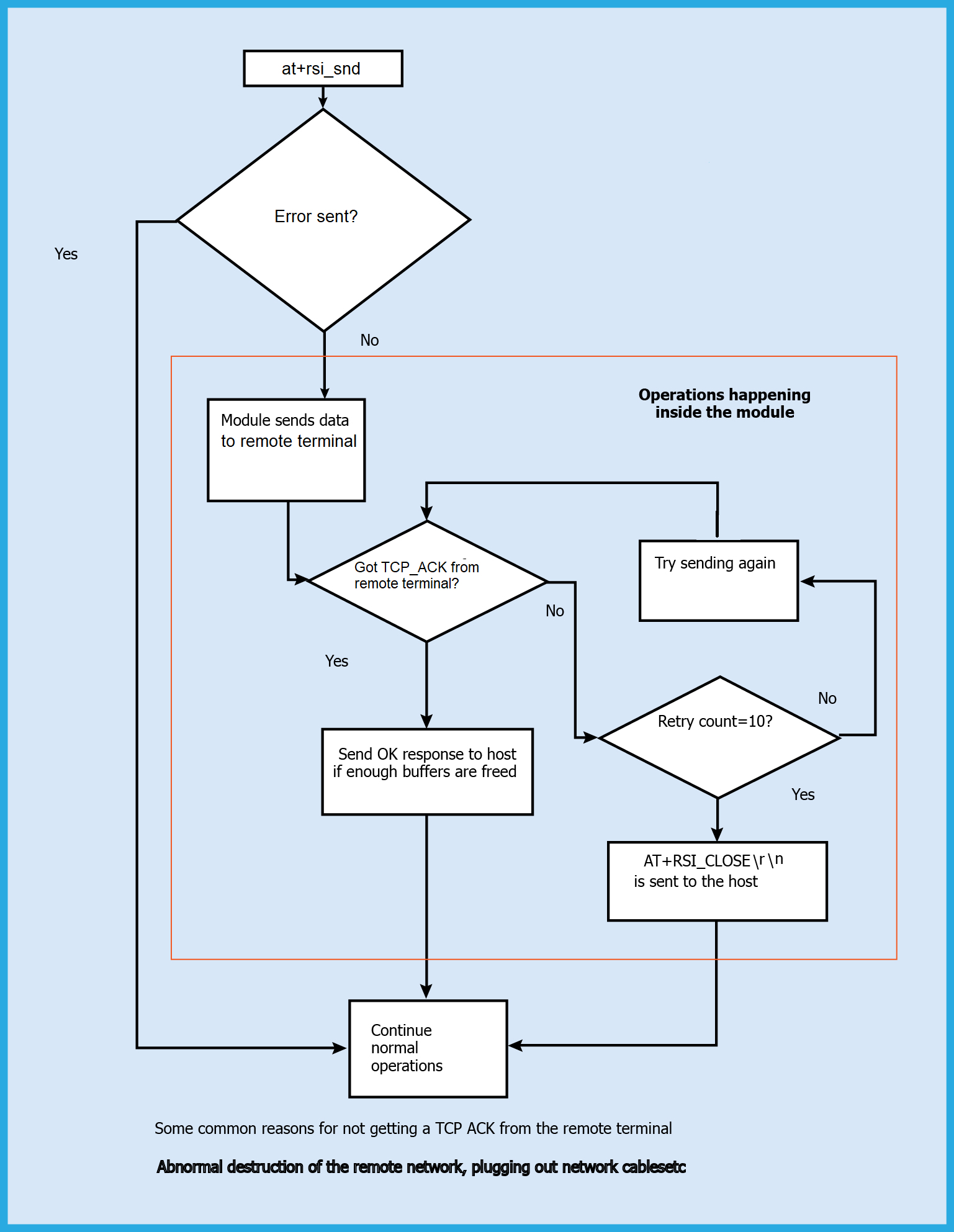
Availability#
This command is available when the module is configured in Operating Mode 0, 2 and 6.
Note! Byte Stuffing is handled as described in the following text.
The '' character sequence (0x0D, 0x0A in hex) is used to indicate the termination of an AT command. If the actual data to be sent from Host comprises of characters in sequence, the host should replace this set of characters with (0xDB) and (0xDC). If (0xDB) itself is part of the data then (0xDB 0xDD ) has to be sent. If (0xDB 0xDC) itself is part of the data then (0xDB 0xDD 0xDC) has to be sent. If either 0xDD or 0xDC is not sent after 0xDB, then an error (-9) is sent.
Example 1. If 0x41 0x42 0x43 0x0D 0x0A is the actual data stream that needs to be sent then the command is
at+rsi_snd <hn> <sz=5> <Dip> <dest_port> <0x41> <0x42> <0x43> <0xDB> <0xDC> <0x0D> <0x0A>Example 2. If 0x41 0x42 0x43 0x0D 0x0A 0x31 0x32 is the actual data stream that needs to be sent then the command is
at+rsi_snd <hn> <sz=7> <Dip> <dest_port> <0x41> <0x42> <0x43> <0xDB> <0xDC> <0x31> <0x32> <0x0D> <0x0A>Example 3. If 0x41 0x42 0x43 0xDB 0x31 0x32 is the actual data stream that needs to be sent then the command is
at+rsi_snd <hn> <sz=7> <Dip> <dest_port> <0x41> <0x42> <0x43> <0xDB> <0xDD> <0x31> <0x32> <0x0D> <0x0A>Example 4. If 0x41 0x42 0x43 0xDB 0xDC 0x31 0x32 is the actual data that needs to be transmitted, then the command is
at+rsi_snd <hn> <sz=8> <Dip> <dest_port> <0x41> <0x42> <0x43> <0xDB><0xDD><0xDC> <0x31><0x32> <0x0D> <0x0A>Example 5. If 0x41 0x42 0x43 0x0D 0x0A 0xDB 0x31 0x32 is the actual data that needs to be transmitted, then the command is
at+rsi_snd <hn> <sz=9> <Dip> <dest_port> <0x41> <0x42> <0x43> <0xDB><0xDC> <0xDB> <0xDD> <0x31> <0x32> <0x0D> <0x0A>Example 6. If 0x41 0x42 0x43 0x0D 0x0A 0xDB 0xDC 0x31 0x32 is the actual data that needs to be transmitted, then the command is
at+rsi_snd <hn> <sz=10> <Dip> <dest_port> <0x41> <0x42> <0x43> <0xDB><0xDC> <0xDB> <0xDD> <0xDC> <0x31> <0x32> <0x0D> <0x0A>at+rsi_snd is the only command that requires byte stuffing to be done by the Host before sending to the module. There are NO other commands (from Host to module) that require byte stuffing. There are NO responses (from module to Host) that are byte stuffed by module before giving to Host.
Example#
Data Stuffing Command Format
To send a data stream 0x01 0x02 0x03 0x04 0x05 0x06 0x07 0x08 0x09 0x0A over a TCP socket.
at+rsi_snd=1,10,0,0, 0x01 0x02 0x03 0x04 0x05 0x06 0x07 0x08 0x09 0x0A 0x61 0x74 0x2B 0x72 0x73 0x690x5F0x730x6E0x64 0x3D 0x31 0x2C 0x31 0x30 0x2C 0x30 0x2C 0x30 0x2C 0x01 0x02 0x03 0x04 0x05 0x06 0x07 0x08 0x09 0x0A 0x0D 0x0ATo send a data stream 0x01 0x02 0x03 0x04 0x05 0x06 0x07 0x08 0x09 0x0A over a UDP socket to a destination IP 192.168.1.20 and destination port 8001.
at+rsi_snd=1,10,192.168.1.20,8001, 0x01 0x02 0x03 0x04 0x05 0x06 0x07 0x08 0x09 0x0A 0x61 0x74 0x2B 0x72 0x73 0x69 0x5F 0x73 0x6E 0x64 0x3D 0x31 0x2C 0x31 0x30 0x2C 0x310x39 0x32 0x2E 0x31 0x36 0x38 0x2E 0x31 0x2E 0x32 0x30 0x2C 0x38 0x30 0x30 0x31 0x2C 0x01 0x02 0x03 0x04 0x05 0x06 0x07 0x08 0x09 0x0A 0x0D 0x0ATo send a stream "abcdefghij" over a Multicast socket.
at+rsi_snd=1,10,239.0.0.0,1900,abcdefghij
0x61 0x74 0x2B 0x72 0x73 0x69 0x5F 0x73 0x6E 0x64 0x3D 0x31 0x2C 0x31 0x30 0x2C 0x32 0x33 0x39 0x2E 0x30 0x2E 0x30 0x2E 0x30 0x2C 0x31 0x39 0x30 0x30 0x2C0x61 0x62 0x63 0x64 0x65 0x66 0x67 0x68 0x69 0x6A 0x0D 0x0AResponse for 250 bytes.
OK 250
0x4F 0x4B 0xFA 0x00 0x0D 0x0AWhen TCP_ACK(bit[2]) is enabled in the socket_bitmap while opening the socket, the send response gives 3 Bytes of which 1 Byte is for socket id and 2 Bytes is for length.
at+rsi_snd=1,10,0,0,0123456789Response.
OK 0x02\0x00
0x4F 0x4B 0x02 0x0A 0x00 0x0D 0x0ATo send data over SSL.
at+rsi_snd=1,10,0,0,hellohelloResponse.
OK
0x4F 0x4B 0x01 0x45 0x00 0x0D 0x0APossible error codes are -2, 63.
[ Go to top ]
rsi_read :: Read Data#
This section explains how to read socket data from the module to host.
Note! To use this feature, BIT(0) should be set in socket_bitmap (TCP/UDP open socket parameter) while opening a socket.
Description#
This command is used to request number of bytes received on given socket. Module will give requested number of bytes received on particular socket (synchronous) only if this command is given from host. If requested numbers of bytes are greater than bytes available on given socket module will return only available number of bytes to host. If no data available on given socket module will wait till data received on given socket to serve this command.
Command Format#
at+rsi_read=<socket_descriptor>,<no of bytes>,<timeout in ms>Parameters#
socket_descriptor (1 byte)
Socket handle of the socket over which data is to be received.
no of bytes (4 bytes)
Length of the data that has to be read from the module.
timeout in milliseconds (2 bytes)
Read timeout in milliseconds to configure read data time out.
Response#
AT+RSI_READ<ip_version><recv_socket><recv_buf_len><ip_address><src_port><recv_data_buf>where ...
ip_version (2 bytes, hex)
IP version of the data received.
4– for IPv4
recv_socket (2 bytes, hex)
Socket handle of the socket over which the data is received. The least significant byte is returned first. If Web socket has been enabled, upper byte holds the web socket info.Seventh bit indicates the FIN packet and bit 3:0 gives the opcode information from web socket header.
recv_buf_len (2 bytes, hex)
Number of bytes received.The least significant byte is sent first. For example, 900 bytes (0x0384) would be sent as <0x84> <0x03>
ap_address (16 bytes)
Source IP address. i.e IP address from which data is received.This field is not present in the message if the data is received over a TCP socket. Only first 4 bytes are filled rest 12 bytes are zero for IPv4 address.
src_port (2 bytes, hex)
Source port. i.e port number from which data is received. This field is not present in the message if the data is received over a TCP socket.
recv_data_buf
Actual received data stream. A maximum of 1472 bytes can be received in case of UDP and 1460 bytes in case of TCP, in this field.When the module sends data to the Host, byte stuffing is NOT done by the module. The size parameter should be used to know how many bytes of valid data is expected. |
Availability#
This command is available when the module is configured in Operating Mode 0, 2 and 6.
Example#
Command
at+rsi_read=1,4,100Response
If abcd is sent from remote terminal to module, on an UDP socket with handle 1, from source IPv4 address 192.168.1.1 to destination IPv4 address 192.168.1.2 (module address) and source port 8001, the module sends the following response to the host.
AT+RSI_READ 4 1 4 192 168 1 1 8001 abcd
0x41 0x54 0x2B 0x52 0x53 0x49 0x5F 0x52 0x45 0x41 0x44 0x04 0x00 0x01 0x00 0x04 0x00 0xC0 0xA8 0x01 0x01 0x41 0x1F 0x61 0x62 0x63 0x64 0x0D 0x0AIf abcd is sent from remote terminal to module, on a TCP socket with handle 1, the module sends the following response to the host.
AT+RSI_READ 4 1 4 abcd
0x41 0x54 0x2B 0x52 0x53 0x49 0x5F 0x52 0x45 0x41 0x44 0x04 0x00 0x01 0x00 0x04 0x00 0x61 0x62 0x63 0x64 0x0D 0x0ANote! The data delivered to the Host on receiving data on a TCP socket does not include the source IP address and source port.
[ Go to top ]
RSI_READ :: Socket Receive Data Notification#
This section explains how the module sends received data to Host.
Note!
The module supports a maximum TLS record size of 4K. If the TLS record size is greater than 4K, the module will close the socket.
To support more than 4K record size, user has to enabled 16K record size. ie., enable BIT [6] in ext_tcp_ip_feature_bit_map.
Description#
The module delivers the data obtained on a socket to the Host with this message. This is an asynchronous response. It is sent from the module to the host when the module receives data from a remote terminal. SSL data is also received in a similar fashion.
Notification Format#
AT+RSI_READ<ip_version><recv_socket><recv_buf_len><ip_address><src_port><recv_data_buf>where ...
ip_version (2 bytes, hex)
IP version of the data received.
4– for IPv4
recv_socket (2 bytes, hex)
socket handle of the socket over which the data is received. The least significant byte is returned first. If Web socket has been enabled, upper byte holds the web socket info.Seventh bit indicates the FIN packet and bit 3:0 gives the opcode information from web socket header.
recv_buf_len (2 bytes, hex)
Number of bytes received.The least significant byte is sent first. For example, 900 bytes (0x0384) would be sent as <0x84> <0x03>
ip_address (16 bytes)
Source IP address. i.e IP address from which data is received.This field is not present in the message if the data is received over a TCP socket. Only first 4 bytes are filled rest 12 bytes are zero for IPv4 address.
src_port (2 bytes, hex)
Source port. i.e port number from which data is received. This field is not present in the message if the data is received over a TCP socket.
recv_data_buf
Actual received data stream. A maximum of 1472 bytes can be received in case of UDP and 1460 bytes in case of TCP, in this field.When the module sends data to the Host, byte stuffing is NOT done by the module. The size parameter should be used to know how many bytes of valid data is expected. |
Availability#
This command is available when the module is configured in Operating Mode 0, 2 and 6.
Example#
Command
at+rsi_read=1,4,100Response for IPv4
If 'abcd' is sent from remote terminal to module, on a UDP socket with handle 1, from source IPv4 address 192.168.1.1 to destination IPv4 address 192.168.1.2 (module address) and source port 8001, the module sends the following response to the host.
AT+RSI_READ 4 1 4 192 168 1 1 8001 abcd
0x41 0x54 0x2B 0x52 0x53 0x49 0x5F 0x52 0x45 0x41 0x44 0x04 0x00 0x01 0x00 0x04 0x00 0xC0 0xA8 0x01 0x01 0x41 0x1F 0x61 0x62 0x63 0x64 0x0D 0x0AIf 'abcd' is sent from remote terminal to module, on a TCP socket with handle 1, the module sends the following response to the host.
AT+RSI_READ 4 1 4 abcd
0x41 0x54 0x2B 0x52 0x53 0x49 0x5F 0x52 0x45 0x41 0x44 0x04 0x00 0x01 0x00 0x04 0x00 0x61 0x62 0x63 0x64 0x0D 0x0ANote! The data delivered to the Host on receiving data on a TCP socket does not include the source IP address and source port.
[ Go to top ]
rsi_fwupok :: Wireless Firmware Update#
Description#
This command is sent as a response to a wireless firmware udpate request.
When user clicks on update button on the wireless update page, module sends an asynchronous message, AT+RSI_FWUPREQ to the host. Upon receiving this message, the host should send wireless firmware update request message if update is required. Host can ignore if update is not required.
Command Format#
at+rsi_fwupokParameters#
N/A
Response#
There is no response for this command.
After successful update, firmware gives a success indication with an asynchronous message as AT+RSI_FWUPSUCCESS. Also "Firmware update successful" pop-up window appears on the browser.
On firmware update failure or host not responding for firmware update request, module gives an error message on pop-up window: "module not responding" on the browser.
Possible error codes are 0x0021, 0x0025, 0x002C, 0x0034
Availability#
This command is available when the module is configured in Operating Mode 0, 2 and 6.
[ Go to top ]
rsi_bgscan :: Background Scan#
Description#
This command is used to scan for Wi-Fi Access Points when the module is in a connected state. The scan results are sorted in decreasing order of signal strength (RSSI value). The scanned access point with highest signal strength will be the first in the list.
Upon issuing this command, RS9116 WiSeConnect validates the channel bit map issued through the scan command, to ensure that background scan is performed only on those channels.
Command Format#
at+rsi_bgscan=<bgscan_enable>,<enable_instant_bgscan>,<bgscan_threshold>,<rssi_tolerance_threshold>,<bgscan_periodicity>,<active_scan_duration>,<passive_scan_duration>,<multi_probe>Parameters#
bgscan_enable (2 bytes)
To enable/disable bgscan
0= Disable1= Enable
enable_instant_bgscan (2 bytes)
If this is set to
enable_instant_bgscan = 1then the module sends probe requests immediately on air and bgscan results will be given to host.
Note!
If the host requires background scan results, then
instant_bg_enableshould be set to1.
bgscan_threshold (2 bytes)
This is the threshold in
dBmto trigger the bgscan. Afterbgscan_periodicity, if connected AP RSSI falls below this value then bgscan will be triggered.
rssi_tolerance_threshold (2 bytes)
This is the difference of the last RSSI of connected AP and current RSSI of connected AP. Here last RSSI is the RSSI calculated at the last beacon received and current RSSI is the RSSI calculated at current beacon received.
If this difference is more than
rssi_tolerance_thresholdthen bgscan will be triggered irrespective of periodicity.
bgscan_periodicity (2 bytes)
This is time period in seconds to trigger bgscan if RSSI of connected AP is above the given
bgscan_threshold(assuming RSSI is a positive value) .
active_scan_duration (2 bytes)
This is active scan duration (in milliseconds) per channel.
passive_scan_duration (2 bytes)
This is passive scan duration (in milliseconds) per DFS channel in the 5 GHz band.
multi_probe (1 byte)
If set to
1the module sends two probe requests, one with specific SSID provided during join command and other with NULL SSID (to scan all access points). If not set, one probe request with connected SSID is sent.
Note!
Channel to scan in background scan is taken from Channel bit maps of scan command , e.g.
channel_bit_map_2_4andchannel_bit_map_5.active_scan_durationshould be less than DTIM period to avoid multicast packet loss.bgscansupports a maximum of 24 channels.
Response#
If instant_bg_enable is disabled:
OKIf instant_bg_enable is enabled:
Result Code | Description |
|---|---|
| Success. |
| Failure |
where ...
scan_count (4 bytes) - Number of Access Points scanned
padding (4 bytes) - Reserved bytes
rf_channel (1 byte) - Channel Number of the scanned Access Point
security_mode (1 byte)
0- Open1– WPA2– WPA23- WEP4– WPA Enterprise5– WPA2 Enterprise7– WPA3 Personal Mode8- WPA3 Personal Transition Mode
rssi_val (1 byte) - RSSI of the scanned Access Point
u_network_type (1 byte) - Network type of the scanned Access Point,
1= Infrastructure mode.ssid (34 bytes) - SSID of the scanned Access Point
bssid (6 bytes) - MAC address of the scanned Access Point
reserved (2 byte) - Reserved bytes.
Possible error codes are 0x0021, 0x0025, 0x002C, 0x004A
Availability#
This command is available when the module is configured in Operating Mode 0, 2.
Example 1#
When instant bgscan is enabled, host will get OK response followed by the response of background scan. Module will do background scanning in the configured channel given in the channel bit map or scan all channels if bitmap is not provided (all non DFS channels in 5GHz) and send the scanned result to host.
Command
at+rsi_bgscan=1,1,63,4,2,50,50,1
0x61 0x74 0x2B 0x72 0x73 0x69 0x5F 0x62 0x67 0x73 0x63 0x61 0x6E 0x3D 0x31 0x2C 0x31 0x2C 0x36 0x33 0x2C 0x34 0x2C 0x32 0x2C 0x35 0x30 0x2C 0x35 0x30 0x2C 0x31 0x0D 0x0AResponse
If two networks are found with the SSID ap_ssid_net1 and ap_ssid_net2", in channels 6 and 11, with measured RSSI of -20 dBm and -14 dBm respectively, the return value is:
OK <scan_count =2><padding><rf_channel =0x0B> <security_mode =0x02> <rssi_val =14> <u_network_type =0x01> <ssid =ap_ssid_net2> <bssid =0x00 0x23 0xA7 0x1F 0x1F 0x15> <reserved><rf_channel =0x06> <security_mode =0x00> <rssi_val =20> <u_network_type =0x01> <ssid =ap_ssid_net1><bssid =0x00 0x23 0xA7 0x1F 0x1F 0x14> <reserved>
0x4F 0x4B 0x02 0x00 0x00 0x00 0x00 0x00 0x00 0x00 0x0B 0x02 0x0D 0x01 0x52 0x65 0x64 0x70 0x69 0x6E 0x65 0x5F 0x6E 0x74 0x32 0x00 0x00 0x00 0x00 0x00 0x00 0x00 0x00 0x00 0x00 0x00 0x00 0x00 0x00 0x00 0x00 0x00 0x00 0x00 0x00 0x00 0x00 0x23 0xA7 0x1F 0x1F 0x15 0x00 0x00 0x06 0x00 0x14 0x01 0x52 0x65 0x64 0x70 0x69 0x6E 0x65 0x5F 0x6E 0x74 0x31 0x00 0x00 0x00 0x00 0x00 0x00 0x00 0x00 0x00 0x00 0x00 0x00 0x00 0x00 0x00 0x00 0x00 0x00 0x00 0x00 0x00 0x00 0x23 0xA7 0x1F 0x1F 0x14 0x00 0x00 0x0D 0x0AExample 2#
When instant bgscan is disabled and when connected, AP RSSI falls below -63dBm (e.g. -65, -68 etc) then bgscan will be triggered at a later time, but the host will only receive the OK message immediately as shown below.
Command
at+rsi_bgscan=1,0,63,4,2,50,50,1
0x61 0x74 0x2B 0x72 0x73 0x69 0x5F 0x62 0x67 0x73 0x63 0x61 0x6E 0x3D 0x31 0x2C 0x30 0x2C 0x36
0x33 0x2C 0x34 0x2C 0x32 0x2C 0x35 0x30 0x2C 0x35 0x30 0x2C 0x31 0x0D 0x0AResponse
OK
0x4F 0x4B 0x0D 0x0A[ Go to top ]
rsi_roam_params :: Roam Parameters#
Description#
This command is used to enable roaming and to set roaming parameters. This command can be issued any time after init command but this command will come into action only after bgscan, see the Roaming Example and Enable Roaming in Open mode as a Client Example.
Command Format#
at+rsi_roam_params= <roam_enable>,<roam_threshold>,<roam_hysteresis>Parameters#
roam_enable (4 bytes)
To Enable/Disable roaming.
0= Disable1= Enable
roam_threshold (4 bytes)#
If connected AP RSSI falls below this value then module will search for a new AP from background scanned list.
roam_hysteresis (4 bytes)#
If module found new AP with same configuration (SSID, Security etc) and if the following relationship is true, then it will try to roam to the new selected AP.
(connected_AP_RSSI – selected_AP_RSSI) > roam_hysteresisResponse#
Result Code | Description |
|---|---|
| Successful execution of command. |
| Failure |
Possible error codes are 0x0021, 0x0025, 0x002C, 0x0026.
Availability#
This command is available when the module is configured in Operating Mode 0,2.
Example#
Command
at+rsi_roam_params=1,67,4
0x61 0x74 0x2B 0x72 0x73 0x69 0x5F 0x72 0x6F 0x61 0x6D 0x5F 0x70 0x61 0x72 0x61 0x6D 0x73 0x3D 0x31 0x2C 0x36 0x37 0x2C 0x34 0x0D 0x0AResponse
OK
0x4F 0x4B 0x0D 0x0ASuggested roaming and background scan configuration for Home environment:
Parameter | Suggested values |
|---|---|
background scan | Enabled |
background scan periodicity | 2 seconds |
background scan threshold | -63 dbm |
background scan tolerance | 4 |
Active scan duration | 50ms |
Passive scan duration | 50ms |
Multiprobe | 0 |
Instant background scan | 1 |
Scan channels | <list of channels in which roaming is expected> |
Roam Threshold | -67dbm |
Roam Hysteresis | 4 |
[ Go to top ]
rsi_ht_caps :: High Throughput Capabilities#
Description#
This command is used to enable high throughput capabilities in the module when operating in AP mode. This command must be issued after the AP configuration parameters command.
Command Format#
at+rsi_ht_caps=<mode_11n_enable>,<ht_caps_bitmap>Parameters#
mode_11n_enable (2 bytes)
Enable/Disable 11n capabilities in AP Mode.
0- Disable1- Enable
ht_caps_bit_map (2 bytes)#
Bit map corresponding to high throughput capabilities.
ht_caps_bit_map | Functionality | Set to | Set to | Description |
|---|---|---|---|---|
|
| Not Supported, set to | ||
| Rx STBC support | Disable | Enable | STA capability of receiving PPDU using STBC (Space Time Block Coding) |
|
| Not Supported, set to | ||
| Short GI for 20Mhz support | Disable | Enable | STA capability to receive frames with a short GI in 20MHz |
| Green field support | Disable | Enable | When set to 1 STA is capable of receiving HT Greenfield PPDU. |
|
| Not Supported, set to | ||
| Channel-width Support | Disable | Enable | 0 for only 20MHz, 1 should not be enabled as 40 MHz bandwidth is not supported, set to |
|
| Not Supported, set to |
Response#
Result Code | Description |
|---|---|
| Successful execution of command. |
| Failure |
Possible error codes are 0x0021, 0x0025, 0x002C, 0x004D.
Availability#
This command is available when the module is configured in Operating Mode 6.
Example#
Command
at+rsi_ht_caps=1,2
0x61 0x74 0x2B 0x72 0x73 0x69 0x5F 0x68 0x74 0x5F 0x63 0x61 0x70 0x73 0x3D 0x31 0x2C 0x32 0x0D 0x0AResponse
OK
0x4F 0x4B 0x0D 0x0A[ Go to top ]
rsi_dnsserver :: DNS Server#
Description#
This command is used to provide the DNS server's IP address to the module. This command should be issued before the "[DNS Resolution]"command and after the "Set IP Parameter" command.
Command Format#
Format for IPv4
at+rsi_dnsserver=<dns_mode>,<primary_dns_ip>,<secondary_dns_ip> Parameters#
dns_mode (8 bytes)
0- Value of0should be used if the user wants to specify a primary and secondary DNS server address.1- The module can obtain DNS Server IP address during the command "Set IP Params" if the DHCP server in the Access Point supports it. In such a case, value of '1' should be used if the module wants to read the DNS Server IP obtained by the module.
primary_dns_ip (16 bytes)
This is the IP address of the Primary DNS server to which the DNS Resolution query will be sent. Should be set to '0' if dns_mode = 1. For IPv4, only the first 4 bytes are used, the remaining 12 bytes are zero.
secondary_dns_ip (16 bytes)
This is the IP address of the Secondary DNS server to which the DNS Resolution query will be sent. If dns_mode = 1 or if the user does not want to specify a secondary DNS Server IP address, this parameter should be set to '0'. For IPv4, only the first 4 bytes are used, the remaining 12 bytes are zero.
Response#
Result Code | Description |
|---|---|
| Successful execution of command. |
| Failure. |
Response
For IPv4, only the first 4 bytes of the IP address are filled, rest 12 bytes are zero.
Possible error codes are 0x0021, 0x0025, 0x002C, 0xFFF8, 0xFF74, 0xBBA8, 0xBBB2, 0xBBAF, 0xBB17, 0xBBB3
Availability#
This command is available in Operating Modes 0, 2, 6 and 9.
Example 1 for IPv4#
Command
at+rsi_dnsserver=1,0,0
0x61 0x74 0x2B 0x72 0x73 0x69 0x5F 0x64 0x6E 0x73 0x73 0x65 0x72 0x76 0x65 0x72 0x3D 0x31 0x2C 0x30 0x2C 0x30 0x0D 0x0AResponse
OK <primary=1.2.3.4><secondary=5.6.7.8>
0x4F 0x4B 0x01 0x02 0x03 0x04 0x00 0x00 0x00 0x00 0x00 0x00 0x00 0x00 0x00 0x00 0x00 0x00 0x05 0x06 0x07 0x08 0x00 0x00 0x00 0x00 0x00 0x00 0x00 0x00 0x00 0x00 0x00 0x00 0x0D 0x0AExample 2 for IPv4#
Command
at+rsi_dnsserver=0,8.8.8.8,0
0x61 0x74 0x2B 0x72 0x73 0x69 0x5F 0x64 0x6E 0x73 0x73 0x65 0x72 0x76 0x65 0x72 0x3D 0x30 0x2C 0x38 0x2E 0x38 0x2E 0x38 0x2E 0x38 0x2C 0x30 0x0D 0x0AResponse
OK <primary=8.8.8.8><secondary=0>
0x4F 0x4B 0x08 0x08 0x08 0x08 0x00 0x00 0x00 0x00 0x0D 0x0A[ Go to top ]
rsi_dnsget :: DNS Resolution#
Description#
This command is to obtain the IP address of the specified domain name.
Command Format#
Format for IPv4
at+rsi_dnsget=<domain_name>,<dns_server_number>,<suppress_dns_response>Parameters#
domain_name (90 bytes)
This is the target domain name. A maximum of 90 characters is allowed.
dns_server_number (2 bytes)
Reserved.
suppress_dns_response (1 byte)
0- Disable suppress_dns_response. User will get DNS response with IP on successful resolution otherwise the error is thrown out.90- Enable suppress_dns_response. When enabled, the firmware will store the IP internally after successful DNS resolution and omits this info from response. This stored IP can then be utilized for subsequent socket connections.
Note!
If the user intends to utilize the stored IP, they should input "0.0.0.0" as the ip_addr and set use_fqdn_resolved_ip to 1 in rsi_tcp and rsi_trans_mode_params.
The stored is cleared when the host issues another DNS query command or the STA disconnects from the AP.
Response#
For IPv4
Result Code | Description |
|---|---|
| Successful execution of command |
| Failure. |
where ...
ip_version (2 bytes) - IP version used, either 4 or 6.
ip_count (2 bytes) - Number of IP addresses individual addresses resolved, up to a maximum of 10. Only first 4 bytes are filled in IPv4 address, rest 12 bytes are zero.
Possible error codes are 0x0015, 0x0021, 0x0025, 0x002C, 0xFFBB, 0xBBA1, 0xBBAA, 0xBBA3, 0xBBA4, 0xBBAC
Availability#
This command is available in Operating Modes 0, 2, 6 and 9.
Example for IPv4#
Command
at+rsi_dnsget=www.silabs.com,1
0x61 0x74 0x2B 0x72 0x73 0x69 0x5F 0x64 0x6E 0x73 0x67 0x 65 0x74 0x3D 0x77 0x77 0x77 0x2E 0x72 0x65 0x64 0x70 0x69 0x6E 0x65 0x73 0x69 0x67 0x6E 0x61 0x6C 0x73 0x2E 0x63 0x6F 0x6D 0x0D 0x0AResponse
OK< ip_version >< uIPCount >< ip_addr1= 201.168.1.100>
0x4F 0x4B 0x04 0x00 0x01 0x00 0xC9 0xA8 0x01 0x64 0x00 0x00 0x00 0x00 0x00 0x00 0x00 0x00 0x00 0x00 0x00 0x00 0x0D 0x0AExample for suppress_dns_response#
Command
at+rsi_dnsget=www.silabs.com,1,90
0x61 0x74 0x2B 0x72 0x73 0x69 0x5F 0x64 0x6E 0x73 0x67 0x65 0x74 0x3D 0x77 0x77 0x77 0x2E 0x72 0x65 0x64 0x70 0x69 0x6E 0x65 0x73 0x69 0x67 0x6E 0x61 0x6C 0x73 0x2E 0x63 0x6F 0x6D 0x2C 0x31 0x5A 0x0D 0x0AResponse
OK
0x4F 0x4B 0x0D 0x0A[ Go to top ]
rsi_dnsupdate :: DNS Update#
Description#
The DNS update functionality enables DNS Client Host to register and to dynamically update their resource records with a DNS server whenever changes occur. If you use this functionality, you can reduce the requirement for manual administration of zone records, especially for clients that frequently move and use Dynamic Host Configuration Protocol (DHCP) to obtain an IP address.
DNS Update will need the Hostname, Domain and the DNS Server specification for dynamic update of client Records
Command Format#
at+rsi_dnsupdate=<ipversion>,<a_zone_name>,<a_host_name>,<dns_server_number>,<ttl>Parameters#
ip_version (1 byte)
IP version used
4- IPv4
a_zone_name(31 bytes)
This is the zone name of the Domain. A maximum of 31 characters is allowed.
a_host_name(31 bytes)
This is the host name of the Domain. A maximum of 31 characters is allowed.
dns_server_number (2 bytes)
DNS Server number.
ttl (2 bytes)
Time To live. Time in seconds for which hostname should be active.
Response#
Result Code | Description |
|---|---|
| Successful execution of command |
| Failure |
Possible error codes are 0x0015, 0x0021, 0x0025, 0x002C, 0xFFBB, 0xBBA1, 0xBBAA, 0xBBA3, 0xBBA4, 0xBBAC
Availability#
This command is available in Operating Modes 0, 2 and 6.
Example#
Command
at+rsi_dnsupdate=4,RPS,silabs,1,53 Response
OK
0x4F 0x4B 0x0D 0x0A[ Go to top ]
rsi_httpget :: HTTP Get#
Description#
This command is used to transmit HTTP GET request from the module to a remote HTTP server. A subsequent HTTP GET request can be issued only after receiving the response of the previously issued HTTP GET request. Module acts as a HTTP client when this command is issued. This command should only be used after IP configuration is complete.
Command Format#
Format for IPv4
at+rsi_httpget=<https_enable>,<http_port>,<user_name>,<password>,<host_name>,<ip_address>,<url>,<extended_header>Parameters#
https_enable
Set BIT[0] to enable HTTPS.
Set BIT[1] to enable NULL delimiter for HTTP buffer instead of comma.
Set BIT[2] to use SSL TLS 1.0 version if HTTPS is enabled.
Set BIT[3] to use SSL TLS 1.2 version if HTTPS is enabled.
Set BIT[4] to use SSL TLS 1.1 version if HTTPS is enabled.
Set BIT[5] to enable
HTTP_POSTdata featureSet BIT[6] to enable HTTP version 1.1.
Set BIT[7] to enable user defined http_content type in Flags.
Note! If SSL/TLS is enabled by default, it will use TLS 1.0 and TLS 1.2. BIT(2) and BIT(3) are valid only when HTTPS is enabled.
http_port
HTTP server port number, defaults to port
80
user_name
The username for HTTP/HTTPS server authentication. Default username is
admin.
password
The password for HTTP/HTTPS server authentication. Default password is
admin.
host_name
Host name of the HTTP/HTTPS server.
ip_address
IP address of HTTP/HTTPS server.
url
Requested URL.
extended_header (1 byte)
The purpose of this is to append user configurable header fields to the default HTTP/HTTPS header. To write extended header, user must use 'Data stuffing' mentioned separately in this document as well mentioning here also in context of extended header. The extended header can have multiple header fields each ended by
\r\n(0xD 0xA) but\r\nis the delimiter for an AT command so use data stuffing and replace all (0xD 0xA) by 0xDB 0xDC besides delimiter(). See the example given below.The default http header contains the following:
Content Type. Describes about the type of the file which user want to send like html, txt, gif, etc.
Content Length. Tells about the length of the text which user is using.
The abovementioned fields are created in the header by the firmware.
Note!
Maximum supported length for
user_name,passwordtogether is278bytes..Maximum supported length for Buffer is
(872-(length of User_name+length of Password))bytes excluding delimiters.If username, password, hostname and extended http headers are not required, user should send empty string separated by delimiter.
If content of any field contains a comma then NULL delimiter should be used.
Host needs to do byte stuffing in extended header field. Please refer the note about data stuffing.
Response#
Module may give http response in multiple chunks for a single HTTP GET request.
Result Code | Description |
|---|---|
| After the module sends out the HTTP GET request to the remote server, it may take some time for the response to come back. The response from the remote server is sent out to the Host from the module in the following form: |
| Failure |
where ...
more (2 bytes)
This indicates whether more HTTP data for the HTTP GET request is pending or not.
0– More data is pending. Further interrupts may be raised by the module till all the data is transferred to the Host.1– End of HTTP data.
status_code (2 bytes)
Provided the HTTP status code as received in the response packet such as
200,201,404etc. a status_code equal to0indicates that there was no HTTP header in the received packet, probably a continuation of the frame body received in the previous chunk.
offset (4 bytes)
Reserved.
data_len (4 bytes)
data length in current chunk.
Data (maximum 1400 bytes)
Actual http data.
Possible error codes for this command are 0x0015, 0x0021, 0x0025, 0x002C, 0xFF74, 0xBBF0
Availability#
This command is available when the module is configured in Operating Mode 0, 2 and 6.
Example 1#
https_enable=0http_port=80Username=usernamepassword=passwordhost_name=www.google.comip_address=192.168.40.86url=/index.htmlextended_header=ContentType: htmlÛÜ
Command
at+rsi_httpget=0,80,username,password,hostname,192.168.40.86,/index.html,ContentType: htmlÛÜExample 2#
Command
at+rsi_httpget=0,80,username,password,hostname,192.168.0.5,/index.html
61 74 2B 72 73 69 5F 68 74 74 70 67 65 74 3D 30 2C 38 30 2C 75 73 65 72 6E 61 6D 65 2C 70 61 73 73 77 6F 72 64 2C 68 6F 73 74 6E 61 6D 65 2C 31 39 32 2E 31 36 38 2E 30 2E 35 2C 2F 69 6E 64 65 78 2E 68 74 6D 6C 2C 0D 0AResponse
AT+RSI_HTTPRSP=<NUL><NUL>È<NUL><NUL><NUL><NUL><NUL>œ<SOH><NUL><NUL><html><head><6/22/2021 18:38:07.082RX] - style type=\"text/css\">body{font- family:Arial;background:#EFF4F3;margin:0;color:#32403f;}#wp{width:600px;margin:0 auto;} p{display:inline-block;font-weight:bold;text-align:right;margin:9px 30px 9px 0;}p,input{width:200px;} h1{text-align:center;font-size:3em;margin:0;padding:20px 0;color:#d6e4e1;border:1px solid #7F8D8C;text-shadow:1px 1px 0 #333;}input{height:24px;border:1px solid #ccc;border-radi<CR><LF> AT+RSI_HTTPRSP=<NUL><NUL><NUL><NUL><NUL><NUL><NUL><NUL><NUL><STX><NUL><NUL>us:4px;padding:2px 5px;margin:0 6px 0 20px;}input:focus{border-color:#32403f;}form{padding-top: 20px;border-top:1px solid #2B3736;}.btn{width:100px;margin:15px 0 15px 250px;font-weight: 700;color:#fff;border:1px solid #000;}h1,.btn{background:#485c5a;background:linear- gradient(#485c5a,#32403f);}.btn:active{background:#32403f;}input[type=checkbox],input[type=radio]{width:16px;height:14px;}#msg{margin:0 0 10px 0;}</style></head><body><h1>Employee Details</ h1><form id=\"fm\" method=\"post\" action=\"#\" onsubmit<CR><LF> AT+RSI_HTTPRSP=<NUL><NUL><NUL><NUL><NUL><NUL><NUL><NUL>N<SOH><NUL><NUL>=\"return pt()\"><div id=\"wp\"></div><p>Employee_name:</p><input id=\"emp_name\" name=\"emp_name\"><p>Employee ID:</p><input id=\"emp_id\" name=\"emp_id\"><p>Designation:</ p><input id=\"designation\" name=\"designation\"><p>Company:</p><input id=\"company\" name=\"company\"><p>Location:</p><input id=\"location\" name=\"location\"><LF><CR>
41 54 2B 52 53 49 5F 48 54 54 50 52 53 50 3D 00 00 C8 00 00 00 00 00 9C 01 00 00 3C 68 74 6D 6C 3E
3C 68 65 61 64 3E 3C
6/22/2021 18:38:07.082RX] - 73 74 79 6C 65 20 74 79 70 65 3D 5C 22 74 65 78 74 2F 63 73 73 5C 22
3E 62 6F 64 79 7B 66 6F 6E 74 2D 66 61 6D 69 6C 79 3A 41 72 69 61 6C 3B 62 61 63 6B 67 72 6F 75 6E
64 3A 23 45 46 46 34 46 33 3B 6D 61 72 67 69 6E 3A 30 3B 63 6F 6C 6F 72 3A 23 33 32 34 30 33 66 3B
7D 23 77 70 7B 77 69 64 74 68 3A 36 30 30 70 78 3B 6D 61 72 67 69 6E 3A 30 20 61 75 74 6F 3B 7D 70
7B 64 69 73 70 6C 61 79 3A 69 6E 6C 69 6E 65 2D 62 6C 6F 63 6B 3B 66 6F 6E 74 2D 77 65 69 67 68 74
3A 62 6F 6C 64 3B 74 65 78 74 2D 61 6C 69 67 6E 3A 72 69 67 68 74 3B 6D 61 72 67 69 6E 3A 39 70 78
20 33 30 70 78 20 39 70 78 20 30 3B 7D 70 2C 69 6E 70 75 74 7B 77 69 64 74 68 3A 32 30 30 70 78 3B
7D 68 31 7B 74 65 78 74 2D 61 6C 69 67 6E 3A 63 65 6E 74 65 72 3B 66 6F 6E 74 2D 73 69 7A 65 3A 33
65 6D 3B 6D 61 72 67 69 6E 3A 30 3B 70 61 64 64 69 6E 67 3A 32 30 70 78 20 30 3B 63 6F 6C 6F 72 3A
23 64 36 65 34 65 31 3B 62 6F 72 64 65 72 3A 31 70 78 20 73 6F 6C 69 64 20 23 37 46 38 44 38 43 3B
74 65 78 74 2D 73 68 61 64 6F 77 3A 31 70 78 20 31 70 78 20 30 20 23 33 33 33 3B 7D 69 6E 70 75 74
7B 68 65 69 67 68 74 3A 32 34 70 78 3B 62 6F 72 64 65 72 3A 31 70 78 20 73 6F 6C 69 64 20 23 63 63
63 3B 62 6F 72 64 65 72 2D 72 61 64 69 0D 0A 41 54 2B 52 53 49 5F 48 54 54 50 52 53 50 3D 00 00 00
00 00 00 00 00 00 02 00 00 75 73 3A 34 70 78 3B 70 61 64 64 69 6E 67 3A 32 70 78 20 35 70 78 3B 6D
61 72 67 69 6E 3A 30 20 36 70 78 20 30 20 32 30 70 78 3B 7D 69 6E 70 75 74 3A 66 6F 63 75 73 7B 62
6F 72 64 65 72 2D 63 6F 6C 6F 72 3A 23 33 32 34 30 33 66 3B 7D 66 6F 72 6D 7B 70 61 64 64 69 6E 67
2D 74 6F 70 3A 32 30 70 78 3B 62 6F 72 64 65 72 2D 74 6F 70 3A 31 70 78 20 73 6F 6C 69 64 20 23 32
42 33 37 33 36 3B 7D 2E 62 74 6E 7B 77 69 64 74 68 3A 31 30 30 70 78 3B 6D 61 72 67 69 6E 3A 31 35
70 78 20 30 20 31 35 70 78 20 32 35 30 70 78 3B 66 6F 6E 74 2D 77 65 69 67 68 74 3A 37 30 30 3B 63
6F 6C 6F 72 3A 23 66 66 66 3B 62 6F 72 64 65 72 3A 31 70 78 20 73 6F 6C 69 64 20 23 30 30 30 3B 7D
68 31 2C 2E 62 74 6E 7B 62 61 63 6B 67 72 6F 75 6E 64 3A 23 34 38 35 63 35 61 3B 62 61 63 6B 67 72
6F 75 6E 64 3A 6C 69 6E 65 61 72 2D 67 72 61 64 69 65 6E 74 28 23 34 38 35 63 35 61 2C 23 33 32 34
30 33 66 29 3B 7D 2E 62 74 6E 3A 61 63 74 69 76 65 7B 62 61 63 6B 67 72 6F 75 6E 64 3A 23 33 32 34
30 33 66 3B 7D 69 6E 70 75 74 5B 74 79 70 65 3D 63 68 65 63 6B 62 6F 78 5D 2C 69 6E 70 75 74 5B 74
79 70 65 3D 72 61 64 69 6F 5D 7B 77 69 64 74 68 3A 31 36 70 78 3B 68 65 69 67 68 74 3A 31 34 70 78
3B 7D 23 6D 73 67 7B 6D 61 72 67 69 6E 3A 30 20 30 20 31 30 70 78 20 30 3B 7D 3C 2F 73 74 79 6C 65
3E 3C 2F 68 65 61 64 3E 3C 62 6F 64 79 3E 3C 68 31 3E 45 6D 70 6C 6F 79 65 65 20 44 65 74 61 69 6C
73 3C 2F 68 31 3E 3C 66 6F 72 6D 20 69 64 3D 5C 22 66 6D 5C 22 20 6D 65 74 68 6F 64 3D 5C 22 70 6F
73 74 5C 22 20 61 63 74 69 6F 6E 3D 5C 22 23 5C 22 20 6F 6E 73 75 62 6D 69 74 0D 0A 41 54 2B 52 53
49 5F 48 54 54 50 52 53 50 3D 00 00 00 00 00 00 00 00 4E 01 00 00 3D 5C 22 72 65 74 75 72 6E 20 70
74 28 29 5C 22 3E 3C 64 69 76 20 69 64 3D 5C 22 77 70 5C 22 3E 3C 2F 64 69 76 3E 3C 70 3E 45 6D 70
6C 6F 79 65 65 5F 6E 61 6D 65 3A 3C 2F 70 3E 3C 69 6E 70 75 74 20 69 64 3D 5C 22 65 6D 70 5F 6E 61
6D 65 5C 22 20 6E 61 6D 65 3D 5C 22 65 6D 70 5F 6E 61 6D 65 5C 22 3E 3C 70 3E 45 6D 70 6C 6F 79 65
65 20 49 44 3A 3C 2F 70 3E 3C 69 6E 70 75 74 20 69 64 3D 5C 22 65 6D 70 5F 69 64 5C 22 20 6E 61 6D
65 3D 5C 22 65 6D 70 5F 69 64 5C 22 3E 3C 70 3E 44 65 73 69 67 6E 61 74 69 6F 6E 3A 3C 2F 70 3E 3C
69 6E 70 75 74 20 69 64 3D 5C 22 64 65 73 69 67 6E 61 74 69 6F 6E 5C 22 20 6E 61 6D 65 3D 5C 22 64
65 73 69 67 6E 61 74 69 6F 6E 5C 22 3E 3C 70 3E 43 6F 6D 70 61 6E 79 3A 3C 2F 70 3E 3C 69 6E 70 75
74 20 69 64 3D 5C 22 63 6F 6D 70 61 6E 79 5C 22 20 6E 61 6D 65 3D 5C 22 63 6F 6D 70 61 6E 79 5C 22
3E 3C 70 3E 4C 6F 63 61 74 69 6F 6E 3A 3C 2F 70 3E 3C 69 6E 70 75 74 20 69 64 3D 5C 22 6C 6F 63 61
74 69 6F 6E 5C 22 20 6E 61 6D 65 3D 5C 22 6C 6F 63 61 74 69 6F 6E 5C 22 3E 0A 0D 0A 41 54 2B 52 53
49 5F 48 54 54 50 52 53 50 3D 01 00 00 00 00 00 00 00 00 00 00 00 0D 0A[ Go to top ]
rsi_httppost :: HTTP Post#
Description#
This command is used to transmit a HTTP POST request to a remote HTTP server.
A subsequent HTTP POST request can be issued only the response to a previously issued HTTP POST request is received. Module acts as a HTTP client when this command is issued.
Use rsi_httppost_data to send multiple chunks (max size 900 byte) of data.
Command Format#
at+rsi_httppost=<https_enable>,<http_port>,<user_name>,<password>,<host_name>,<ip_address>,<url>,<extended_header>,<data/data_length>Parameters#
https_enable
Set BIT[0] to enable HTTPS.
Set BIT[1] to enable NULL delimiter for HTTP buffer instead of comma.
Set BIT[2] to use SSL TLS 1.0 version if HTTPS is enabled.
Set BIT[3] to use SSL TLS 1.2 version if HTTPS is enabled.
Set BIT[4] to use SSL TLS 1.1 version if HTTPS is enabled.
Set BIT[5] to enable
HTTP_POSTdata featureSet BIT[6] to enable HTTP version 1.1.
Set BIT[7] to enable user defined http_content type in Flags
http_port
HTTP server port number, defaults to port
80
user_name
The username for HTTP/HTTPS server authentication. Default username is
username.
password
The password for HTTP/HTTPS server authentication. Default password is
admin.
host_name
Host name of the HTTP/HTTPS server.
ip_address
IP address of HTTP/HTTPS server.
url
Requested URL.
extended_header (1 byte)
The purpose of this is to append user configurable header fields to the default HTTP/HTTPS header. To write extended header, user must use 'Data stuffing' mentioned separately in this document as well mentioning here also in context of extended header. extended header can have multiple header fields each ended by
\r\n(0xD 0xA) but\r\nis the delimiter for an AT command so use data stuffing and replace all (0xD 0xA) by 0xDB 0xDC besides delimiter(). See the example given below.The default http header contains the following:
Content Type : Describes about the type of the file which user want to send like html,txt,gif etc.
Content Length : Tells about the length of the text which user is using.
The abovementioned fields are created in the header by the firmware.
data/data_length
Post data to be sent / total length of the http data.
Note!
When BIT[6] is enabled in
https_enablefeature bitmap,hostnameis mandatory (to support HTTP version 1.1).When BIT[5] is enabled in
https_enablefeature bitmap, instead of data, the host need to give total HTTP data length.Maximum supported length for
user_name,passwordtogether is278bytes.Maximum supported length for buffer is
(872-(length of user_name + length of password))bytes excluding delimiters.If username, password, hostname and extended http headers are not required, user should send empty string separated by delimiter.
If content of any field contains comma then NULL delimiter should be used.
Example 1#
https_enable=0http_port=80Username=usernamepassword=passwordhost_name=www.google.comip_address=192.168.40.50url=/index.htmlextended_header=ContentType: htmlÛÜdata=<data>
Example 2#
Set BIT[5] in https_enable field.
https_enable=0x20http_port=80Username=usernamepassword=passwordhost_name=posttestserver.comip_address=64.90.48.15url=/post.phpextended_header=ContentType: htmlÛÜdata=1800
Note!
As per httppost_data, maximun bytes of data length is 1400 only.
As per above example, sending data length as 1800 bytes but will post the data chunk by chunk i.e. 1400 bytes will be sent followed by the remaining 400 bytes.
Response#
Module may give http response in multiple chunks for a single HTTP POST request.
Result Code | Description |
|---|---|
| After the module sends out the HTTP POST request to the remote server, it might take some time to receive the response. The response from the remote server is sent out to the Host from the module in the following form: |
| Failure |
where ...
more (2 bytes)
This indicates whether more HTTP data for the HTTP POST request is pending or not.
0More data is pending. Further interrupts may be raised by the module till all the data is transferred to the Host.1End of HTTP data.2HTTP post request success response.
status_code (2 bytes)
Provided the HTTP status code as received in the response patcket such as
200,201,404etc. Astatus_codeequal to 0 indicates that there was no HTTP header in the received packet, probably a continuation of the frame body received in the previous chunk.
offset (4 bytes)
Reserved
data_len (4 bytes)
The data length in current chunk.
data (Maximum 1400 bytes)
Actual http data.
Possible error codes for this command are 0x0015, 0x0021, 0x0025, 0x002C, 0xFF74, 0xBBF0
Availability#
This command is available when the module is configured in Operating Mode 0, 2, 6 and 9.
Example 1#
Command
at+rsi_httppost=1,443,username,password,hostname,192.168.40.86,/index.html, ContentType: **html**ÛÜ,<data=abcd>Example 2#
Command
at+rsi_httppost=32,80,username,password,posttestserver.com,64.90.48.15,/index.html, ContentType: **html**ÛÜ, 100
at+rsi_httppost=65,443,username,password,posttestserver.com,64.90.48.15,/index.html,ContentType: **html**ÛÜ, 100
at+rsi_httppost=97,443,username,password,posttestserver.com,64.90.48.15,/index.html,ContentType: **html**ÛÜ, 100[ Go to top ]
rsi_httppost_data :: HTTP Post Data#
Description#
This command is used to transmit chunks of HTTP data to http server.
To use this command it is MANDATORY to enable large data transfer using https_enable[5] in the at+rsi_httppost command.
A subsequent `HTTP POST data request can be issued only when the response to a previously issued HTTP POST DATA request is received. Module acts as a HTTP client when this command is issued.
Command Format#
at+rsi_httppost_data=<current_chunk_length>,<data>current_chunk_length
Length of the current data.
data
HTTP data.
Response#
Module may give http response in multiple chunks for a single HTTP POST request.
Result Code | Description |
|---|---|
| After the module sends out the HTTP POST request to the remote server, it might take some time to receive the response. The response from the remote server is sent out to the Host from the module in the following form |
| Failure |
where ...
more (2 bytes)
This indicates whether more HTTP data for the HTTP POST request is pending or not .
4= More data is pending from host5= End of HTTP data from host(Host sent total data content length)8= More data is pending from module to host. Further interrupts may be raised by the module till all the data is transferred to the Host.9= End of HTTP data from module to host.
status_code (2 bytes)
Provided the HTTP status code as received in the response packet such as 200, 201, 404 etc. A status_code equal to 0 indicates that there was no HTTP header in the received packet, probably a continuation of the frame body received in the previous chunk.
offset (4 bytes)
Always contains „0?.
data_len (4 bytes)
data length in current chunk.
data (maximum 1400 bytes)
Actual http data.
Possible error codes for this command are as follows 0x0015,0x0021, 0x0025, 0x002C, 0xFF74, 0xBBF0, 0XBB38, 0xBBEF, 0xBB3E, 0xBB38, 0xBBE7.
Availability#
This command is available when the module is configured in Operating Mode 0, 2 and 6 .
Example#
Command
at+rsi_httppost=32,80,username,password,posttestserver.com,64.90.48.15,/index.html,ContentType: **html**ÛÜ, 1800
ok successful responseat+rsi_httppost_data=1400,<first 1400 byte of total 1800 byte data>
ok successful responseat+rsi_httppost_data=400,<last 400 byte of total 1800 byte data>
ok successful response[ Go to top ]
rsi_httpput :: HTTP Put#
Description#
This command is used to transmit HTTP PUT request to a remote HTTP server. Module acts as a HTTP client when this command is issued. This section explains different commands to use HTTP client PUT. This command should only be issued afterSet IP Parameterscommand. The following table explains the list of HTTP PUT commands and their description.
HTTP PUT Command | Description |
|---|---|
PUT_CREATE | Creates HTTP client thread and HTTP client socket. This should be the first command to use the HTTP client PUT |
PUT_START | Connects to the specified HTTP server and creates the specified resource. |
PUT_PACKET | To send the resource data packet |
PUT_DELETE | To delete the HTTP client thread and socket |
PUT_CREATE should be called as a first command to use HTTP PUT.
Once put start is successful, PUT_PACKET should be called to send the resource data packet for the previously create resource.
Once put create is successful, PUT_START should be called to create the specified resource on the specified HTTP server.
Call PUT_DELETE to delete HTTP Client thread and socket.
Command Format#
The HTTP PUT client has different command types. Based on the command type, following parameters change accordingly.
For at+rsi_httpput=<command_type>,<remaining parameters> the following are available command types.
HTTP PUT command | Command Type | Command Format |
|---|---|---|
PUT create | 1 |
|
PUT start | 2 |
|
ip_version = 4 | ||
ip_address = IP address of the HTTP server. | ||
port number = HTTP server port number | ||
total_length = Total content length of the HTTP PUT data | ||
http_buffer = http buffer contains the username, password, host name, ip address, URL address, extended http header. | ||
PUT PACKET | 3 |
|
current length = length of the current http put content chunk | ||
http_buffer = http buffer contains the put data | ||
PUT DELETE | 4 |
|
Note!
Maximum supported PUT buffer length is 900 bytes.
Maximum timeout for http put start command response is 20 Seconds.
Maximum timeout for http put packet command response is 10 Seconds.
https_enable
Set BIT[0] to enable HTTPS.
Set BIT[1] to enable NULL delimiter for HTTP buffer instead of comma.
Set BIT[2] to use SSL TLS 1.0 version if HTTPS is enabled.
Set BIT[3] to use SSL TLS 1.2 version if HTTPS is enabled.
Set BIT[4] to use SSL TLS 1.1 version if HTTPS is enabled.
Set BIT[5] to enable
HTTP_POSTdata featureSet BIT[6] to enable HTTP version 1.1.
Set BIT[7] to enable user defined http_content_type in flags.
port_number
HTTP server port number. If not specified, defaults to port
80.
http_put_buffer
This is a character bufer that contains following values in the order of
<user_name>,<password>,<host_name>,<address>,<url>,<extended_header>.
content_length
Total length of the resource content.
user_name
user_name for HTTP/HTTPS server authentication. Default user name is 'redpine'.
password
password for HTTP/HTTPS server authentication. Default password is 'admin'.
host_name
Host name of the HTTP/HTTPS server.
ip_address
IPv4/IPv6 address(IPv6 is cuurently not supported) of HTTP/HTTPS server.
url
Requested URL.
extended_header
The purpose of this is to append user configurable header fields to the default HTTP/ HTTPS header. To write extended header through 'at' command, user must use 'Data stuffing' mentioned separately in this document as well as in context of extended header mentioned here. Extended header can have multiple header fields each ended by (oxd oxa). But here is our delimiter for whole 'at' command, so use data stuffing and replace all (0xd 0xa) by 0xdb oxdc besides delimiter()
current_length
Current content chunk length
data
Resource data to be sent. This parameter is valid only for the
PUT PACKETcommand.
Note!
Maximum supported length for
user_name,passwordtogether is278bytes.Maximum supported length for buffer is
(872-(length of user_name + length of password))bytes excluding delimiters.If username, password, hostname and extended http headers are not required, user should send empty string separated by delimiter.
If content of any field contains comma then NULL delimiter should be used.
When BIT[6] is enabled in
https_enablefeature bitmap,hostnameis mandatory (to support HTTP version 1.1).When BIT[6] is enabled in
https_enablefeature bitmap,hostnameis mandatory (to support HTTP version 1.1).
Response#
Result Code | Description |
|---|---|
| After the module sends out the HTTP PUT request to the remote server, it may take some time for the response to come back. The response from the remote server is sent out to the Host from the module in the following form: |
| Failure |
where ...
command_type
"5", HTTP Client PUT packet command type during the response from the server.
end_of_file
Only valid for `HTTP_PUT PKT.
End of file or HTTP resource content.
8- More data pending from server9- End of HTTP file from server/resource content
offset (4 bytes)
Reserved
data_length
Data length in current chunk
data
(Maximum 1024 bytes) Actual http data from server.
Possible Error codes for this command are 0x0021, 0x0015, 0x0025, 0xBB38.
Availability#
This command is available in Operating Modes 0, 2, 6.
Example#
HTTP client PUT Service
Command
at+rsi_httpput=1
at+rsi_httpput=2,4,0,80,19,username,password,192.168.1.100,192.168.1.100,/,ContentType: **html**ÛÜ
at+rsi_httpput=3,19,<html><body></html>
at+rsi_httpput=4[ Go to top ]
rsi_fwversion :: Query Firmware Version#
Description#
This command queries the version of the firmware loaded in the module.
Command Format#
at+rsi_fwversion?Response#
Result Code | Description |
|---|---|
OK | Successful execution of command. All values returned in ASCII. |
| Failure. |
where ...
firmware_version (20 bytes)
The firmware version of the module.
Possible error codes for this command are 0x002C.
Availability#
This command is available in all modes.
Example#
Command
at+rsi_fwversion?
0x61 0x74 0x2B 0x72 0x73 0x69 0x5F 0x66 0x77 0x76 0x65 0x72 0x73 0x69 0x6F 0x6E 0x3F 0x0D 0x0AResponse from RS9116 Rev 1.4
OK1610.2.5.0.0.23
0x4F 0x4B 0x31 0x36 0x31 0x30 0x2E 0x32 0x2E 0x35 0x2E 0x30 0x2E 0x30 0x2E 0x32 0x33 0x00 0x0D 0x0AResponse from RS9116 Rev 1.5
OK1611.2.5.0.0.23
0x4F 0x4B 0x31 0x36 0x31 0x31 0x2E 0x32 0x2E 0x35 0x2E 0x30 0x2E 0x30 0x2E 0x32 0x33 0x00 0x0D 0x0A[ Go to top ]
rsi_rssi :: Query RSSI Value#
Description#
This command is used to retrieve the RSSI value for Access Point to which the module is connected.
Command Format#
at+rsi_rssi?Response#
Result Code | Description |
|---|---|
OK <rssi_val> | Successful execution of command |
| Failure. |
where ...
rssi_val (2 bytes)
Absolute value of the RSSI of the Access Point to which the module is connected. For example, if the RSSI is -20 dBm,
rssi_val=20.Closer the RSSI value to
0, stronger the signal strength.
Possible error codes for this command are 0x0021, 0x0025, 0x002C.
Availability#
This command is available when the module is configured in Operating Mode 0 and 2.
Example#
Command
at+rsi_rssi?
0x61 0x74 0x2B 0x72 0x73 0x69 0x5F 0x72 0x73 0x73 0x69 0x3F 0x0D 0x0AResponse For a RSSI of -20 dBm, the return string is
OK20
0x4F 0x4B 0x14 0x00 0x0D 0x0A[ Go to top ]
rsi_mac :: Query MAC Address#
Description#
This command is used to query the MAC address of the module. This command can be issued anytime after rsi_init command.
Command Format#
at+rsi_mac?Response#
For Non-concurrent Mode#
Result Code | Description |
|---|---|
OK <MAC_Address> | Successful execution of command. The MAC address (6 bytes) of the module. |
| Failure. |
For Concurrent Mode#
| OK <MAC_Address1><MAC_Address2>| Successful execution of command. MAC_Address1 is the station MAC Address and MAC_Address2 is of the AP created in the module.|
| ERROR <Error code> | Failure. |
Possible error codes for this command are 0x002c.
Availability#
This command is available in all operating modes.
Example 1 - Client or AP mode#
Command
at+rsi_mac?
0x61 0x74 0x2B 0x72 0x73 0x69 0x5F 0x6D 0x61 0x63 0x3F 0x0D 0x0AResponse
If the MAC ID is 80:C9:55:34:F0:10, the response is
OK <MAC_Address>
0x4F 0x4B 0x80 0xC9 0x55 0x34 0xF0 0x10 0x0D 0x0AExample 2 - Concurrent mode#
Command
at+rsi_mac?
0x61 0x74 0x2B 0x72 0x73 0x69 0x5F 0x6D 0x61 0x63 0x3F 0x0D 0x0AResponse
OK <MAC_Address1><MAC_Address2>
0x4F 0x4B 0x80 0xC9 0x55 0x34 0xF0 0x10 0x80 0xC9 0x55 0x34 0xF0 0x11 0x0D 0x0A [ Go to top ]
rsi_nwparams :: Query Network Parameters#
Description#
This command is used to retrieve the WLAN and IP configuration parameters. This command should be sent only after the connection to an Access Point is successful.
Command Format#
at+rsi_nwparams?Response#
Result Code | Description |
|---|---|
| Successful execution of command |
| Failure. |
where ...
wlan_state (1 byte)
This indicates whether the module is connected to an Access Point or not.
0– Not Connected1– Connected
channel_number (1 byte)
Channel number of the AP to which the module is connected
psk (64 bytes)
Pre-shared key used
mac_addr (6 bytes)
MAC address of the module
ssid (34 bytes)
This value is the SSID of the Access Point to which the module is connected.
Note: The maximum length of SSID is 32 bytes; the remaining 2 bytes are reserved for NUL termination and alignment.
connection_type (2 bytes)
0x0001– Infrastructure
sec_type (1 byte)
Security mode of the AP to which the module joined.
0– Open mode1– WPA security2– WPA2 security3- WEP4– WPA-Enterprise5– WPA2-Enterprise7– WPA3 Personal Mode8- WPA3 Personal Transition Mode
dhcp_mode (1 byte)
This value indicates whether the module is configured for DHCP or Manual IP configuration.
0– Static IP configuration1– Dynamic IP configuration
ip_addr (4 bytes)
This is the IP address of the module.
subnet_mask(4 bytes)
This is the Subnet Mask of the module
gateway (4 bytes)
This is the Gateway Address of the module.
num_open_socks (2 bytes)
This value indicates the number of sockets currently opened
prefix_length (2 bytes)
Prefix length of IPv6 address(currently not supported).
ip6 (16 bytes)
Not used since IPv6 is not supported.
dgw6(16 bytes)
Not used since IPv6 is not supported.
tcp_stack_used (1 byte)
Defaults to
1to indicate IPv4.
socket_id (2 bytes)
Socket handle of an existing socket
socket_type (2 bytes)
0– TCP/SSL/websocket Client2– TCP/SSL Server (Listening TCP)4– Listening UDP
local_port (2 bytes)
Port number of the socket in the module.
dest_port(2 bytes)
dest_port of the remote peer.
ip_address (16 bytes)
IP address of the remote terminal.
Only first 4 bytes of IP address is filled, remaining 12 bytes are zero.
Note! If the Set IP Params command was not sent to the module before Query Network Parameters command, the module returns default values for the following fields: dhcp_mode, ip_addr, subnetMask, gateway, num_open_socks, prefix_length, ip6, dgw6, tcp_stack_used, socket_info
Possible error codes for this command are 0x0021, 0x002C.
Availability#
This command is available when the module is configured in Operating Mode 0, 2.
Example#
Command
at+rsi_nwparams?
0x61 0x74 0x2B 0x72 0x73 0x69 0x5F 0x6E 0x77 0x70 0x61 0x6D 0x73 0x3F 0x0D 0x0AResponse
Response when rsi_nwparams command is given before ipconfig command so ip parameters are not set in this response, and sockets are not opened yet. Here SSID is 'cisco' and gateway is '192.168.100.76'.
OK <wlan_state><channel_number><psk><mac_addr><ssid><connection_type><sec_type><dhcp_mode><ip_addr><subnet_mask><gateway><num_open_socks><prefix_length><ip6><dgw6><tcp_stack_used><socket_id><socket_type><local_port><dest_port><dest_ip_address>
OK <wlan_state =0x01><channel_number =0x06><psk =0x00(repeats 63 times)><mac_addr =0x00 0x23 0xA7 0x16 0x16 0x16><ssid =0x63 0x69 0x73 0x63 0x6F 0x00<repeats 27 times><conection_tType =0x01 0x00><sec_type =0x00 > <dhcp_mode =0x01><ip_addr =0x00 0x00 0x00 0x00><subnetMask =0xFF 0xFF 0xFF 0x00 0><gateway =0xC0 0xA8 0x64 0x4C><num_open_socks =0x00 0x00><prefix_length =0x00 0x00><ip6 =0x00(16times)><dgw6=0x00(16 times) ><socket_id =0x00 0x00><socket_type =0x00 0x00><local_port =0x00 0x00><dest_port =0x00 0x00><dstip_addr.ipv4_address/ dstip_addr.ipv6_address =0x00 0x00 0x00 0x00 0x00 0x00 0x00 0x00 0x00 0x00 0x00 0x00 0x00 0x00 0x00 0x00><repeats 11 times > 0x0D 0x0A.Note!
Command will not fetch PSK, instead it will fetch PMK which is stored to reduce connection time with AP from the next boot up. In the nwparams response structure you can find 32 bytes of PMK and the rest is filled with zeroes.
If the FEAT_HIDE_PSK_CREDENTIALS bit is set in feature_bit_map, then the PSK field is hidden from the user, i.e. filled with zeroes.
[ Go to top ]
rsi_reset :: Soft Reset#
Description#
This command resets the module, including all information regarding the WLAN connection and IP configuration. After giving this command, the Host has to start from the beginning, from Auto Baud Rate Detection (ABRD) for device detection and issuing the first command "Set Operating Mode". This command is valid only in case of UART / USB-CDC interface.
There is no response for this command.
Command Format#
at+rsi_resetParameters#
N/A
Response#
N/A
Availability#
This command is available in all operating modes.
Example#
Command
at+rsi_reset
0x61 0x74 0x2B 0x72 0x73 0x69 0x5F 0x72 0x65 0x73 0x65 0x74 0x0D 0x0AResponse None
[ Go to top ]
rsi_multicast_filter :: Multicast Filter#
Description#
This command is to configure the multicast MAC address bitmap to filter multicast packets. This command should be given after init command.
Command Format#
at+rsi_multicast_filter=<mcast_bitmap_frame>Parameters#
mcast_bitmap_frame
There are two bytes in the payload which represent 2 parts. Lower byte represent the command type (cmd as mentioned below) and higher byte is the hash value (6 Bits) generated from the desired multicast MAC address (48 Bits) using hash function.
mcast_bitmap_frame | Functionality |
|---|---|
| These 2 bits represents the command type. Possible values are as follows ... |
| |
| |
| |
| |
| reserved |
| 6 bit hash value generated from the hash algorithm which corresponds to the multicast MAC address is used to set/reset corresponding bit in multicast filter bitmap.This field is valid only if 0 or 1 is selected in command type(mcast_bitmap_frame[0:1]) |
| reserved |
Response#
Result Code | Description |
|---|---|
| Successful execution of command. |
| Failure. |
Possible error codes are 0x0021, 0x0025, 0x002c.
Availability#
This command is available when the module is configured in Operating Mode 0, 2 and 6.
Note!
The Hash function is generated using CRC-8 with the polynomial x^8 + x^2 + x + 1. Only 6 bits are provided as the hash input to mcast_bitmap_frame[8:13], the 2 MSBs are ignored.
[ Go to top ]
rsi_multicast :: Join/Leave Multicast Group#
Description#
This command is used to join or leave a multicast group. This command should be issued after IP config done. The module can only join a single Multicast group at a time.
Command Format#
at+rsi_multicast=<request_type>,<ip_address>Parameters#
reqest_type (2 bytes)
Type of request.
0- Leave multicast group1- Join multicast group
ip_address (16 bytes)
IP address of the multicast group. The last 12 bytes should be set to
0.
Response#
Result Code | Description |
|---|---|
| Successful execution of command. |
| Failure. |
Possible error codes 0x0021, 0x0025, 0x002C, 0xBB21, 0xBB4c, 0xBB17, 0xBB55.
Availability#
This command is available when the module is configured in Operating Mode 0, 2 and 6.
Example 1 - Join a multicast group#
Command
at+rsi_multicast=1,239.0.0.0
0x61 0x74 0x2B 0x72 0x73 0x69 0x5F 0x6D 0x75 0x6C 0x74 0x69 0x63 0x61 0x73 0x74 0x3D 0x31 0x2C 0x32 0x33 0x39 0x2E 0x30 0x2E 0x30 0x2E 0x30 0x0D 0x0AResponse
OK
0x4F 0x4B 0x0D 0x0AExample 2 - Leave a multicast group#
Command
at+rsi_multicast=0,239.0.0.0
0x61 0x74 0x2B 0x72 0x73 0x69 0x5F 0x6D 0x75 0x6C 0x74 0x69 0x63 0x61 0x73 0x74 0x3D 0x30 0x2C 0x32 0x33 0x39 0x2E 0x30 0x2E 0x30 0x2E 0x30 0x0D 0x0AResponse
OK
0x4F 0x4B 0x0D 0x0ANote! If mDNS feature is enabled, multicast group is not supported.
[ Go to top ]
rsi_ping :: ICMP Ping#
Description#
This command is used to send and ICMP ping to the target IP address. This command should be issued after IP config is done. To enable, set PING from module which is tcp_ip_feature_bit_map[11].
Command Format#
at+rsi_ping=<ip_version>,<ping_address>,<ping_size>,<timeout_ms>Parameters#
ip_version (2 bytes)
IP version of the ping request.
4- for IPv4
ping_size (2 bytes)
Ping data size to send. Maximum supported is 300 bytes.
ping_address (16 bytes)
Destination IPv4/IPv6 address.
timeout_ms (2 bytes)
Ping request timeout.
Response#
Result Code | Description |
|---|---|
| Successful execution of command |
| Failure. |
where ...
ip_version (2 bytes)
IP version of the ping reply.
ping_size (2 bytes)
Contains the length of the data which is present in the ping reply.
ping_address (16 bytes)
IP address of the ping reply. Last 12 bytes are set to '0' in case of IPv4.
Availability#
This command is available when the module is configured in Operating Mode 0, 2 or 6.
Possible error codes are 0x0025, 0x002C, 0x002F, 0xBB29, 0xFF74, 0x0015, 0xBB21, 0xBB4B, 0xBB55.
Example
Command
at+rsi_ping=4,192.168.1.100,10
0x61 0x74 0x2B 0x72 0x73 0x69 0x5F 0x70 0x69 0x6E 0x67 0x3D 0x34 0x2C 0x31 0x39 0x32 0x2E 0x31 0x36 0x38 0x2E 0x31 0x2E 0x31 0x30 0x30 0x2C 0x31 0x30 0x0D 0x0AResponse 0x4F 0x4B 0x04 0x00 0x0A 0x00 0xC0 0xA8 0x01 0x64 0x00 0x00 0x00 0x00 0x00 0x00 0x00 0x00 0x00 0x00 0x00 0x00 0x0D 0x0A
[ Go to top ]
rsi_webpage :: Write Static Webpage#
RS9116W allows two kinds of webpages to be stored in flash: static and dynamic. Static pages allow plain html, css and JavaScript; whereas dynamic pages allow JSON data to be associated with the static webpages. This JSON data can be stored, retrieved and updated independently. The webpages can fetch this data and dynamically fill form fields. These fields can be modified from the host side or the browser.
The host can store up to 10 webpages, each up to 4K in size. The size of a page can exceed the 4K limitation, but this will result in lesser number of files that can be stored. For example, user could store one 12K file, and seven 4K files. Similarly, there can be 10 JSON data objects with each NOT exceeding 512 bytes in any circumstances. These objects can only be stored if they have an associated webpage.
Description#
This command is used to load a static webpage, to store a static webpage and to overwrite an existing static webpage. This command should be issued before join command.
If webpage total length is more than MAX_WEBPAGE_SEND_SIZE, then host has to send webpage in multiple chunks.
Command Format#
at+rsi_webpage=<filename>,<total_len>,<current_len>,<has_json_data>,<webpage>Parameters#
filename (24 bytes)
Name of the file to load the webpage.
*total_len (2 bytes)
Total length of the webpage
current_len (2 bytes)
Length of the current webpage chunk
has_json_data
has_json_data (1 byte)
0- if no associated data. In this case webpage is static page.1- if file has associated json data
webpage (1024 bytes)
The HTML content chunk.
Response#
Result Code | Description |
|---|---|
| Successful execution of command. |
| Failure. |
Possible error codes are 0x0021, 0x0015, 0x0025, 0x00C1, 0x00C2, 0x00C3 , 0x00C5, 0x00C6, 0x00C8
Availability#
This command is available when the module is configured in Operating Mode 0, 2 and 6.
Example#
The host can also overwrite an existing page, this is achieved by issuing this same command with the same filename. No explicit erase is required. However the size of the new file cannot exceed the size of the old file rounded up to the 4K chunk boundary. Precisely, if an old file used 2 chunks of 4K i.e. up to 8K in size, then the new file can't exceed 8K in size. To overcome this limitation, the host should erase the existing file and then write a new file which can exceed the size of the old file provided the device has enough space available.
Command
at+rsi_webpage=sample.html,2783,1024,0,<html><head><title></title>[1024-chars]Response
OK [ Go to top ]
rsi_jsoncreate :: Write Dynamic Webpage#
Description#
This command is used to write to flash json data associated with static webpages.
Command Format#
at+rsi_jsoncreate=<filename>,<total_len>,<current_len>,<json_data>Parameters#
filename (24 bytes)
The webpage file with which this JSON data is associated.
total_length (2 bytes)
Total length of the JSON
current_length(2 bytes)
Length of current JSON chunk
json_data
This is the JSON Object that stores the data of the webpage. The maximum supported JSON length is 512 bytes.
Response#
Result Code | Description |
|---|---|
OK | Success. |
| Failure. |
There is no response payload.
Possible error codes are 0x0015, 0x0021, 0x0025, 0x002C, 0x00B1, 0x00B2,0x00B3, 0x00B4, 0x00B5, 0x00B6.
Availability#
This command is available when the module is configured in Operating Mode 0, 2 and 6.
Example#
The webpage associated with the dynamic webpage data should already be present in the flash with has_json_data = 1 before issuing this command.
Command
at+rsi_jsoncreate=sample.html,60,60,{"temp":27, "accx":2.4, "accy":2.6, "accz":1.1, "enabled":true}Response
OKNote! The webpage associated with the dynamic webpage data should already be present in the flash with bool json set to 1 before issuing this command.
[ Go to top ]
rsi_erasefile :: Erase Static Webpage#
This command is used to erase the webpage file from flash memory. This command should be issued before join command. The erase command should be used specifying the filename, this will free up the number of 4K chunks the existing file was using.
Command Format#
at+rsi_erasefile=<filename> Parameters#
filename (24 bytes)
Name of the webpage file to be erased.
Response#
Result Code | Description |
|---|---|
| Successful execution of command. |
| Failure. |
There is no response payload.
Possible error codes are 0x0021, 0x0025,0x002C, 0x00C4
Availability#
This command is available when the module is configured in Operating Mode 0, 2 and 6.
Example#
Command
at+rsi_erasefile=sample.htmlResponse
OK[ Go to top ]
rsi_erasejson :: Erase Dynamic Webpage#
This command is used to erase the JSON data file associated with a webpage in the flash memory. This command should be issued after opermode command.
Command Format#
at+rsi_erasejson=<filename> Parameters#
filename (24 bytes)
Name of the webpage file of which JSON data is to be erased.
Response#
Result Code | Description |
|---|---|
| Successful execution of command. |
| Failure. |
There is no response payload.
Possible error codes are 0x0021, 0x0025, 0x002C, 0x00B4.
Availability#
This command is available when the module is configured in Operating Mode 0, 2 and 6.
Example#
at+rsi_erasejson=sample.htmlResponse
OK
[ Go to top ]
rsi_clearfiles :: Erase All Webpages#
Description#
This command is used to erase all webpages in the file system. This command should be issued after opermode command.
Command Format#
at+rsi_clearfiles=<clear> Parameters#
clear (1 byte)
set '1' to clear files.
Response#
Result Code | Description |
|---|---|
| Successful execution of command. |
| Failure. |
There is no response payload.
Possible error codes are 0x0021, 0x0025, 0x002C.
Availability#
This command is available when the module is configured in Operating Mode 0, 2 and 6.
Example#
Command
at+rsi_clearfiles=1Response
OK
[ Go to top ]
rsi_urlrsp :: Webpage Passthrough#
Description#
If a request for an unknown URL (webpage) with a .html extension is received, the module sends an asynchronous indication message AT+RSI_URLREQ to the host to request the unknown webpage. The host responds with the webpage content using the rsi_urlrsp command.
After receiving an AT+RSI_URLREQ message, the host should provide the module with the webpage to serve. The format of the asynchronous indication sent to the host is shown below.
AT+RSI_URLREQ <length><url_name><request_type> <post_content_length><post_data> where ...
url_length (1 byte)
The number of characters in the requested URL.
url_name (40 bytes)
The URL name.
request_type (1 byte)
The type of request received
0– HTTP GET request1– HTTP POST request
post_content_length (2 bytes)
The length of the posted content
post_data (512 bytes)
The HTTP POST received.
Note!
The post_content_length and post_data fields are valid if request_type is HTTP POST. These fields can be ignored if request_type is HTTP GET.
Command Format#
at+rsi_urlrsp=<total_len>,<more_chunks>,<webpage>Parameters#
total_len (4 bytes)
This is the total number of characters in the webpage. If the queried web page is not found, the Host should send
0for this parameter.
more_chunks (1 byte)
0- There are no more segments coming from the Host after this segment1- There is one or more segments coming from the Host after this segment
webpage (1400 bytes)
Source for the current webpage segment
Response#
Result Code | Description |
|---|---|
| Successful execution of command. |
| Failure. |
There is no response payload.
Possible error codes are 0x0015, 0x0021, 0x0025, 0x002C.
Availability#
This command is available when the module is configured in Operating Mode 0, 2 and 6.
Example 1#
If the web page source code is of 3000 characters, the Host should send it through 3 segments, the first two of 1400 bytes, and the last one of 200 bytes as shown:
Command
at+rsi_urlrsp=<total_len =3000>,<more_chunks =1>, <webpage =code of the 1st segment>
at+rsi_urlrsp=<total_len =3000>,<more_chunks =1>, <webpage =code of the 2nd segment>
at+rsi_urlrsp=<total_len =3000>,<more_chunks =0>, <webpage =code of the 3rd segment>Example 2#
If the requested webpage can not be served e.g. the page is unknown, the host should send the following command
Command
at+rsi_urlrsp=0[ Go to top ]
rsi_setregion :: Set Regulatory Region for Client Mode#
Description#
This command configures the device to operate according to the regulations of its operating region. This command should be given immediately followed by init command.
Command Format#
at+rsi_setregion=<setregion_code_from_user_cmd>,<region_code>/r/nParameters#
setregion_code_from_user_cmd (1 byte)
Enable/Disable set region code from user.
0– Disable. Use the region information from beacon IE (Information Element)1- Enable. Use the region information from user command
For the
Rest of Worldregion, there is no support for automatically configuring the region from a beacon IE.
region_code (1 byte)
0,1- USA (Default)2- Europe3- Japan4- Rest of World (all radio channels are enabled with this setting)5- Korea
Response#
Result Code | Description |
|---|---|
| Successful execution |
| Failure |
where ...
region_code (1 byte)
0x01 - USA
0x02 - Europe
0x03 - Japan
0x04 - Rest of World
0x05 - Korea
Possible error codes for this command are 0x0021, 0x0025, 0x002C, 0xFF82, 0x00CC, 0x00C7, 0x00CD, 0x00CE
Note!
In dual band mode, if the country element is extracted from a beacon in 2.4GHz band and 5GHz band are not matching, an error is thrown and region is set to US
Refer to the following tables for the region supported and rules followed by the module
Although the transmit power levels w.r.t to region are greater than 20dBm, the module supports maximum Tx power output of 18dBm.
For RS9116AC0 and RS9116AC1 module as STA :-
Region configuration from user is not allowed.
In 2.4GHz, USA is configuerd as default country domain and in addition to this, channels 12 and 13 are passively scanned.
Country inforamtion is updated as per connecting AP's beacon before authentication.
Upon disconnection with the AP, STA will switch to USA domain along with channels 12 and 13 are passively scanned.
While doing passive scan (channel 12 and 13) if any beacon is found in that channel STA will switch to active scan.
If there is no country IE in the beacon of the AP to which STA is going to connect, STA will switch to USA/EU country based on the channel in which the AP exists. For example if the AP in channel between 1 to 11, STA will configure to USA else if the current channel number is 12 or 13 STA will be configured to EU.
US Domain Regulations#
Rule No | Band | First Channel | # Channels | Last Channel | Max power in dBm | Scan type |
|---|---|---|---|---|---|---|
1 | 2.4 GHz | 1 | 11 | 11 | 27 | Active |
2 | 5 GHz | 36 | 4 | 48 | 16 | Active |
3 | 5 GHz | 52 | 4 | 64 | 23 | Passive |
4 | 5 GHz | 100 | 5 | 116 | 23 | Passive |
5 | 5 GHz | 132 | 3 | 140 | 23 | Passive |
6 | 5 GHz | 149 | 5 | 165 | 29 | Active |
Europe Domain Regulations#
Rule No | Band | First Channel | # Channels | Last Channel | Max power in dBm | Scan type |
|---|---|---|---|---|---|---|
1 | 2.4 GHz | 1 | 13 | 13 | 20 | Active |
2 | 5 GHz | 36 | 4 | 48 | 23 | Active |
3 | 5 GHz | 52 | 4 | 64 | 23 | Passive |
4 | 5 GHz | 100 | 10 | 140 | 30 | Passive |
Japan Domain Regulations#
Rule No | Band | First Channel | # Channels | Last Channel | Max power in dBm | Scan type |
|---|---|---|---|---|---|---|
1 | 2.4GHz | 1 | 13 | 13 | 20 | Active |
2 | 5GHz | 36 | 4 | 48 | 20 | Active |
3 | 5GHz | 52 | 4 | 64 | 20 | Passive |
4 | 5GHz | 100 | 10 | 140 | 30 | Passive |
Korea Domain Regulations#
Rule No | Band | First Channel | # Channels | Last Channel | Max power in dBm | Scan type |
|---|---|---|---|---|---|---|
1 | 2.4 GHz | 1 | 13 | 13 | 20 | Active |
2 | 5 GHz | 36 | 4 | 48 | 20 | Active |
3 | 5 GHz | 52 | 4 | 64 | 20 | Passive |
4 | 5 GHz | 100 | 11 | 140 | 30 | Passive |
5 | 5 GHz | 149 | 5 | 165 | 30 | Active |
Availability#
This command is available when the module is configured in Operating Mode 0, 2, 8 modes. The tabulated rules are followed for the regions supported by the module.
Example#
Set the region to 'Rest of World'.
Command
at+rsi_setregion=1,4Response
OK
[ Go to top ]
rsi_setregion_ap :: Set Regulatory Region for AP Mode#
Description#
This command is used to set the region of the module in Access point mode. This command helps device to self-configure and operate according to the regulations of its operating country and includes parameters like country name, channel quantity and maximum transmit power. These parameters are added in Country information element in the beacons and probe responses. This command should be immediately followed by init command.
Command Format#
at+rsi_setregion_ap=<setregion_code_from_user_cmd>,<country_code>,<num_rules>,[<first_channel>,<num_channels>,<max_tx_power>, ...] repeated for each rule.Parameters#
setregion_code_from_user_cmd (1 byte)
Set region code from user command enable/disable
0- Disable. Get the region information based on region code from module's internal memory1- Enable. Get the region information from user command
country_code (3 bytes)
Country code is case sensitive and should be in Upper case. If
setregion_code_from_user_cmd=1,country_codemust be set toUS,EU,JPorKR.If the country code is 2 characters, 3rd character should be
<space>.The following parameters are considered only if
setregion_code_from_user_cmd=1.
num_rules (4 byte)
Number of rules for a given regulatory domain; at least
1rule must be provided.
first_channel (1 byte)
First channel for the nth rule. For 2.4GHz, only 2.4GHz channels need to be provided, and for 5GHz, only 5GHz channels need to be provided.
num_channels (1 byte)
Number of channels contained in a rule.
max_tx_power (1 byte)
Maximum transmit power used for channels in a rule.
Response#
Result Code | Description |
|---|---|
| Successful execution |
| Failure |
Possible error codes for this command are 0x0021, 0x0025, 0x002C, 0x00ca, 0x00cb, 0x00cc, 0xFF71, 0xFF82
Availability#
This command is available when the module is configured in Operating Mode 6.
Note!
AP configuration in DFS (Dynamic Frequency Selection) channels (52 to 140) is not supported.
Though the transmit power levels w.r.t region are greater than 20dBm, the module only supports a maximum transmit power of 18dBm
For RS9116AC0/RS9116AC1 module as AP:-
Region configuration from user is not allowed.
USA is configured as default country.
In concurrent mode, country domain is configured to that of AP's country domain to which the STA has connected.
Example 1#
Example for 2.4 GHz
Command
at+rsi_setregion_ap=1,US<space>,2,1,4,23,5,7,30Consider the first rule 1,4,23
The first channel is
1and the number of channels is4. This rule enables channels[1,2,3,4]to transmit at a power level up to23 dBm.
Consider the second rule 5,7,30
The first channel is
5and the number of channels is7. This rule enables channels[5,6,7,8,9,10,11]to transmit at a power level up to30 dBm.
The Country code given in the command reflects as it is in the beacon frame.
Example 2#
Example for 5 GHz
Command
at+rsi_setregion_ap=1,US<space>,2,40,4,23,149,3,30Consider the first rule 40,4,23
The first channel is
40and the number of channels is4. This rule enables channels[40,44,48,52]to transmit at a power level up to23 dBm.
Consider the second rule 149,3,30
The first channel is
149and the number of channels is3. This rule enables channels[149,153,157]to transmit at a power level up to30 dBm.
Example 3#
Set the region using a previously stored configuration.
Command
at+rsi_setregion_ap=0,US<space>Response
OK
Note! Refer to the tables dcoumented in the Set Region command for the region supported and domain rules followed by the module.
[ Go to top ]
rsi_per_stats :: Query PER Statistics#
Description#
Returns Transmit and Receive packet statistics once per second.
Command Format#
at+rsi_per_stats=<per_stats_enable>,<per_stats_channel>Parameters#
per_stats_enable (2 bytes)
0– Enable1– Disable
per_stats_channel (2 bytes)
Channel number used to receive packet statistics (not required if stats are disabled)
Response#
Result Code | Description |
|---|---|
| Success |
| Failure |
The format of packet statistics is shown in the following table.
AT+RSI_PER_STATS=<reserved_1>,<reserved_2>,
<reserved_3>,<crc_pass>,<crc_fail>,<cca_stk>,<cca_not_stk>,<pkt_abort>,<fls_rx_start>,<cca_idle>,<reserved_4>,
<rx_retries>,<reserved_5>,
<cal_rssi>,<reserved 6>,
<xretries>,<max_cons_pkts_dropped>,<reserved 7>
<bss_broadcast_pkts>,<bss_multicast_pkts>,<bss_filter_matched_multicast_pkts>,
<eof_pkt_drop_count>,<mask_pkt_drop_count>,<no_of_acks_sent>,
<pkt_rcvd with 48M>,<pkt rcvd with 24M>,<pkt rcvd with 12M>,<pkt rcvd with 6M>,
<pkt rcvd with 54M>,<pkt rcvd with 36M>,<pkt rcvd with 18M>,<pkt rcvd with 9M>,
<pkt rcvd with 11M>,<pkt rcvd with 5M>,<pkt rcvd with 2M>,<pkt rcvd with 1M>,
<pkt rcvd with mcs0>,<pkt rcvd with mcs1>,<pkt_rcvd_with_mcs2>,<pkt_rcvd_with_mcs3>,
<pkt_rcvd_with_mcs4>,<pkt_rcvd_with_mcs5>,<pkt_rcvd_with_mcs6>,<pkt_rcvd_with_mcs7>Response#
Field | Size (bytes) | Description |
|---|---|---|
reserved_1 | 2 | Reserved |
reserved_2 | 2 | Reserved |
reserved_3 | 2 | Reserved |
crc_pass | 2 | Number of RX packets that passed CRC |
crc_fail | 2 | Number of RX packets that failed CRC |
cca_stk | 2 | Number of times cca got stuck |
cca_not_stk | 2 | Number of times cca didn't get stuck |
pkt_abort | 2 | Number of times RX packet aborts happened |
fls_rx_start | 2 | Number of false rx starts.If Valid wlan packet is recived and is dropped due to some reasons |
cca_idle | 2 | CCA idle time |
reserved_4 | 26 | Reserved |
rx_retries | 2 | Number of RX retries happened |
reserved_5 | 2 | Reserved |
cal_rssi | 2 | The calculated RSSI value of recently received RX packet |
reserved_6 | 4 | Reserved |
xretries | 2 | Number of TX Packets dropped after maximum retries |
max_cons_pkts_dropped | 2 | Number of consecutive packets dropped after maximum retries |
reserved_7 | 2 | Reserved |
bss_broadcast_pkts | 2 | BSSID matched broadcast packets count |
bss_multicast_pkts | 2 | BSSID matched multicast packets count |
bss_filter_matched_multicast_pkts | 2 | BSSID and multicast filter matched packets count. The filtering is based on the parameters given in multicast filter commandSet/Reset Multicast filter]. If multicast filter is not set then this count is equal to bss_multicast_pkts count |
Possible error codes for this command are 0x0021, 0x0025, 0x002c, 0x000A#
NOTE! reserved fields: Rest of the fields other than the above mentioned are reserved and can be ignored#
Note!
In PER mode (opermode 8), the following stats related to RX packets (crc_pass, crc_fail, cca_stk, cca_not_stk, pkt_abort, fls_rx_start, cca_idle,cal_rssi) are only valid, the remaining fields can be ignored.
The multicast stats are valid only in associated state in client mode and are invalid in non-associated state. In associated state, the stats are for packets which are destinated for the module's MAC address only. In non-associated state, the stats are for all the packets received, irrespective of the destination MAC address.
Parameters valid in modes other than PER mode (opermode = 0, 2, 6) are : cal_rssi, xretries, crc_pass, max_cons_pkts_dropped, crc_fail, cca_stk, cca_not_stk, pkt_abort, fls_rx_start, cca_idle, bss_broadcast_pkts, bss_multicast_pkts, bss_filter_matched_multicsast_pkts
Availability#
This command is valid in all operating modes.
[ Go to top ]
RSI_CLOSE :: Remote Socket Close Notification#
Description#
This is an asynchronous message issued in the following cases.
When the remote peer closes connected TCP/SSL/Web socket.
When module is not able to send data over socket because of unavailability of remote peer.
When remote peer becomes unreachable, the module closes the socket after TCP keep alive time (~20 minutes) and sends this message to host.
Notification Format#
AT+RSI_CLOSE<socket_desc><bytes_sent>where ...
socket_desc (2 bytes)
Socket descriptor of the socket which is closed.
bytes_sent (4 bytes)
Number of bytes sent successfully on that socket
Availability#
This command is available when the module is configured in Operating Mode 0, 2 and 6.
[ Go to top ]
rsi_bytes_sent_count :: Query Socket Tx Byte Count#
Description#
This command is used to query the number of bytes successfully transmitted (by the module) on a given socket.
Command Format#
at+rsi_bytes_sent_count=<socket_handle>Parameters#
sock_handle (1 byte)
The handle of the socket to query.
Response#
Result Code | Description |
|---|---|
| Success |
| Failure |
where ...
socket_handle (2 bytes)
The handle of the socket.
num_bytes_sent (4 bytes)
Number of bytes successfully transmitted on the socket.
Possible error codes for this command are 0xFF86, 0XFFFA, 0xFF82, 0x002C, 0x0025, 0x0021.
Availability#
This command is available when the module is configured in Operating Mode 0, 2 and 6.
Example#
Command
at+rsi_bytes_sent_count=1
0x61 0x74 0x2B 0x72 0x73 0x69 0x5F 0x62 0x79 0x74 0x65 0x73 0x5F 0x73 0x65 0x6E 0x74 0x5F 0x63 0x6F 0x75 0x6E 0x74 0x3D 0x31 0x0D 0x0AResponse
OK <socket_handle><num_bytes_sent>
0x4F 0x4B 0x01 0x00 0x0E 0x00 0x00 0x00 0x0D 0x0A[ Go to top ]
rsi_debug :: Configure UART Debug Printing#
Description#
This command is used to enable debug prints on UART interfaces 1 and 2. Debug prints are controlled using the assertion level and assertion type parameters. This command should be issued after the device is initialized.
To select the UART, see ext_custom_feature_bit_map[27]
UART 1GPIO_9is Tx (to host MCU)GPIO_8is Rx (from host MCU)
UART 2GPIO_6is Tx (to host MCU). Used exclusively for serial debug logging.
Command Format#
at+rsi_debug=<assertion_type>,<assertion_level>Parameters#
assertion_type (4 byte)
Possible values are 0 to 15.
assertion_level (4 byte)#
The assertion level is in the range
0to15(lowest to highest).0disables all the prints.
Note!
To disable debug prints, send the
rsi_debugcommand withassertion_typeandassertion_levelset to0.The baud rate for UART 2 is 460800.
Response#
Result Code | Description |
|---|---|
| Success |
| Failure |
Possible error codes for this command are 0x0021, 0x0025, 0x002C, 0xFFF8
Availability#
This command can be given at any time.
[ Go to top ]
RSI_STATE-X :: Connection State Notification#
Description#
Asychronous messages are used to indicate module state to host. Asynchronous message are enabled by setting bit 10 of the custom feature bitmap during, see rsi_opermode .
Command Format#
N/A
Response#
This type of asynchronous message is given by the module when it is in scanning state.
AT+RSI_STATE-I<time_stamp>,<state_code>,<reason_code>,<rsi_channel>,<rsi_rssi>,<rsi_bssid>This kind of message is given by the module once the scan results are observed and decided to join or not to join/Rejoin to AP.
AT+RSI_STATE-II<time_stamp>,<state_code>,<reason_code>,<rsi_channel>,<rsi_rssi>,<rsi_bssid>Once the association or disassociation is done, module will give final state asynchronous message.
AT+RSI_STATE-III<time_stamp>,<state_code>,<reason_code>,<rsi_channel>,<rsi_rssi>,<rsi_bssid>where ...
time_stamp (4 bytes)
This is the value of the time stamp counter at the time of message; timestamps increment at intervals of 100ms.
state_code (1 byte)
This field indicates the state of the module.
state_codecontains two parts, the upper nibble and lower nibble.The upper nibble indicates the state of the rejoin process. The following table documents the possible values of the upper nibble of
state_code.
State | Upper Nibble | Indication |
|---|---|---|
Scan Trigger (State I) |
| Startup. Initial Roam |
| Beacon Loss. Failover Roam | |
| De-authentication. AP induced roam / Disconnect from supplicant | |
Scan Result/Decision (State II) |
| Current AP is best |
| Better AP found | |
| No AP found | |
Final Connection (State III) |
| Associated |
| Unassociated |
The lower nibble of
state_codeindicates the reason for a state change. The following table documents the possible values of the lower nibble ofstate_code.
Lower Nibble | Reason for State Change |
|---|---|
| No reason specified |
| No response from AP for authentication request(Authentication denial) |
| Association denial |
| User configured AP is not present |
| EAPOL TX failure |
| Deauthentication from user |
| PSK not configured |
| key-handshake failure during rejoin/roaming/after connection(Disconnection from supplicant) |
| Roaming not enabled |
reason_code (1 byte)
Indicates the reason for a failure.
These failures include EAP certificate errors during connection.
| Reason for state change failure |
|---|---|
| No reason specified |
| No response from AP for authentication request(Authentication denial) |
| Association denial |
| User configured AP is not present |
| EAPOL TX failure |
| Deauthentication from user |
| PSK not configured |
| key-handshake failure during rejoin/roaming/after connection(Disconnection from supplicant) |
| Roaming not enabled |
| Beacon Loss (failover Roam) |
| De-authentication (AP induced Roam/Deauth from supplicant) |
| TLS CA Cert not present |
| TLS PRIVATE key not present |
| TLS Client Cert not present |
| TLS no Cert present |
| PEAP CA Cert not present |
| Server Cert Invalid Key Type |
| Server Intermediate CA Invalid Key Type |
| Server Root CA Invalid Key Type |
| Client Cert Invalid Key Type |
| Client Root CA Invalid Key Type |
| FIPS Server Cert Invalid Length |
| FIPS Server Intermediate CA Invalid Length |
| FIPS Server Root CA Invalid Length |
| FIPS Client Cert Invlaid Length |
| FIPS Client Root CA Invalid Length |
| Server Cert 4096-bit length support is not enabled |
| Server Intermediate CA 4096-bit length support is not enabled |
| Server Root CA 4096-bit length support is not enabled |
| Client Cert 4096-bit length support is not enabled |
| Client Root CA 4096-bit length support is not enabled |
| Server Cert Invalid Sign Alg |
| Server Intermediate CA Invalid Sign Alg |
| Server Root CA Invalid Sign Length |
| Client Cert Invalid Sign Alg |
| Client Root CA Invalid Sign Length |
| Server Intermediate CA not Present |
| Server Root CA Parse Error |
| Server Intermediate Root CA Parse Error |
| Sever Cert Parse Error |
| Client Cert Parse Error |
| Incorrect Private Key Password |
| EAP Failure Received |
| Client Cert Bad Date Error |
| Server Cert Bad Date Error |
| Server Root CA Bad Date Error |
| Client Root CA Bad Date Error |
| Server Intermediate Root CA Bad Date Error |
| Pem Header Error |
| Pem Footer Error |
| Client Intermediate CA Invalid Sign Length |
| Client Intermediate CA Invalid Length |
| FIPS Client Intermediate CA Invalid Length |
| Client Intermediate CA invalid Key Type |
| Pem Error |
| Pathlen certificate is Invalid |
--- | |
Note |
In addition to the above, reason code received in Deauthentication/Disassociation frame from AP is added. This will set the MSB bit of reason_code.
If MSB bit is set in reason code, then mask it with 0x7f to get the acutal reason code received in Deauthentication/Disassociation frame.
In RS9116 Rev 1.4, above reason codes will come only in TCP/IP bypass mode.
Pem Header Error(0x4D) or Pem Footer Error(0x4E) are only applicable if certificates are loaded individually. In case if certificates are loaded combinedly in a single file, only Pem Error(0x53) will be triggered for Header or Footer errors.
rsi_channel (1 byte)
Following represents the meaning of AP channel at the given state.
State-I - Associated radio channel (invalid at startup).
State-II - Channel of next association if module finds better AP in bgscan result.
State-III - Channel at the time of association.
If value of rsi_channel is 0, it means channel information is not available.
rsi_rssi (1 byte)
Following represents the meaning of AP RSSI at the given state.
State-I - RSSI of AP at the time of trigger.
State-II - RSSI of next association.
State-III - RSSI at the time of final association.
If value of
rsi_rssi=100, the RSSI information is not available.
rsi_bssid (6 bytes)
Following represents the meaning of AP MAC at the given state.
State-I - MAC address of AP at the time of scan trigger.
State-II - MAC address of AP at the time of next association.
State-III - MAC at the time of association.
If the value of AP MAC is
00:00:00:00:00:00, it means MAC information is not available.
Availability#
This command is available in oper modes 0, 2 and 6.
Note!
By default this feature is disabled. To enable this feature, set the custom bit 0x400 in opermode command.
[ Go to top ]
RSI_CLIENT_STATION_CONNECTED :: Client Connection Notification#
Description#
Asychronous messages used to indicate to the host in AP mode when a station connects (frame type 0xC2) / or disconnects (frame type 0xC3).
Notification Format#
Client connected message.
AT+RSI_CLIENT_STATION_CONNECTED=<client_mac_address>Client disconnected message.
AT+RSI_CLIENT_STATION_DISCONNECTED=<client_mac_address>where ...
mac_address (6 bytes)
MAC address of station connected/disconnected
Availability#
This command is valid when opermode is 6.
Possible Error Codes#
N/A
[ Go to top ]
rsi_trans_mode_params :: Transparent Mode Command#
Description#
In transparent mode, the module acts as a virtual serial line. Once the module enters into the transparent mode, it will take raw data (byte stream) from a host on a serial port and forward it to the remote device using an internal TCP/IP stack. Similarly, data received from remote devices passed to the host (by discarding TCP/IP protocol-specific header) through a serial line. In transparent mode, the module does not process AT commands. This command is used to Enter/Start transparent mode, parameters for transparent mode are to be provided in this command. On reception of this command, the module tries to start transparent mode and replies with AT+RSI_TMODE message with status.
Command Format#
at+rsi_trans_mode_params=<packetization_length>,<escape_character>,<gap_time>,<frame_time>,<escape_time>,<ip_version>,<socket_type>, <local_port>,<dest_port>,<ip_address>,<max_count>,<type_of_service>,<ssl_parameters>,<ssl_ciphers>,<use_fqdn_resolved_ip>Parameters#
packetization_length (2 bytes)
Possible values are 10 to 1024
escape_character (1 byte)
Any special character
This is a special character, which has significance. If module receives three consecutive escape characters from host after
gap_time, this escape sequence indicates that the module should exit from Transparent mode and move into Command mode.
gap_time (2 bytes)
Varies from 0 to 65533 in milliseconds
frame_time (2 bytes)
Varies from 1 to 65534 in milliseconds (must be greater than gap time)
escape_time (2 bytes)
Varies from 2 to 65535 in milliseconds (must be greater than frame time)
ip_version (2 bytes)
Must be
4for IPv4
socket_type (2 bytes)
0– TCP1– UDP2– LTCP4– LUDP
local_port (2 bytes)
Local port number
dest_port (2 bytes)
Destination port number
ip_address (4 bytes)
Server IP address if socket type is LUDP/LTCP
max_count (2 bytes)
Maximum number of clients in LUDP/LTCP, fixed to 1 in transparent mode.
type_of_service (4 bytes)
Type of service, varies from
0to8
ssl_parameters (1 byte)
This field is used to enable SSL for selected socket.
0– Open TCP socket.1- Open SSL client socket.4- Open SSL socket with TLS 1.0 version.8- Open SSL socket with TLS 1.2 version.
ssl_ciphers (1 byte)
Select various cipher modes, possible values
2-TLS_RSA_WITH_AES_256_CBC_SHA2564-TLS_RSA_WITH_AES_128_CBC_SHA2568-TLS_RSA_WITH_AES_256_CBC_SHA16-TLS_RSA_WITH_AES_128_CBC_SHA32-TLS_RSA_WITH_AES_128_CCM_864-TLS_RSA_WITH_AES_256_CCM_8
use_fqdn_resolved_ip (1 byte)
0- Disable the use of fqdn resolved ip address.1- Enable the use of fqdn resolved ip address.
Note!
If user want to enable use_fqdn_resolved_ip then user must have to give ip_address as '0.0.0.0' as input.
Response#
Result Code | Description |
|---|---|
| Successfully entered into transparent mode. It also displays the remote/server IP details |
| Graceful exit from Transparent mode (by giving escape sequence from host after escape time) |
| Exited from transparent mode due to WiFi disconnected. |
| Exited from transparent mode due to TCP remote terminate from peer. |
| Exited from transparent mode due to TCP retries over terminated TCP connection. |
| Did not enter transparent mode due to invalid transparent mode params. |
| Did not enter transparent mode due to module doesn't have IP |
| Did not enter transparent mode as could not create requested socket. |
| Failure. Possible error codes for this command are |
Availability#
This command can be given only after successful connection with AP, module should have a valid IP and there should be no prior sockets opened.
Note!
For LTCP sockets, on remote socket disconnection, the rsi_trans_mode_params AT command has to be given again for a new connection.
Ouput Format for only AT+RSI_TMODE0
AT+RSI_TMODE0<ip_ver><dest_port><dest_ip_addr>[ Go to top ]
rsi_hfc :: UART Hardware Flow Control#
Description#
This command is used to Enable/Disable UART hardware flow control. This command should be issued after initialization.
Command Format#
at+rsi_hfc=<hfc_config>Parameters#
hfc_config (1 byte)
Enable or Disable UART hardware flow control, and select which pins are used for RTS/CTS.
0- Disable hardware flow control1- Enable hardware flow control using the following pins for RTS/CTSUART_RTS=GPIO_7UART_CTS=GPIO_11
2- Enable hardware flow control using the following pins for RTS/CTSUART_RTS=GPIO_12UART_CTS=GPIO_15
Response#
Result Code | Description |
|---|---|
| Success |
| Failure |
Possible error codes for this command are 0x004E, 0x002C
Note!
Hardware flow control feature is not supported in Auto-Join/Auto-Create mode. To enable this feature, rsi_hfc should be called separately.
[ Go to top ]
rsi_socket_config :: Socket Configuration Parameters#
Description#
This command sets socket configuration parameters; configuration of sockets is recommended, but optional. Based on the socket configuration, the module will use the available buffers effectively. This command should be given after IP configuration command and before any socket creation.
Command Format#
at+rsi_socket_config=<total_sockets>,<total_tcp_sockets>,<total_udp_sockets>,<tcp tx only sockets>,<total_tcp_rx_only_sockets>,<total_udp_tx_only_sockets>,<total_udp_rx_only_sockets>,<total_tcp_rx_high_performance_sockets>,<tcp_rx_window_size_cap>,<ack window division factor>Parameters#
total_sockets (1 byte)
Desired total number of sockets to open.
total_tcp_sockets (1 byte)
Desired total number of TCP sockets to open.
total_udp_sockets (1 byte)
Desired total number of UDP sockets to open.
tcp_tx_only_sockets (1 byte)
Desired total number of TCP sockets to open which are used only for data transmission.
tcp_rx_only_sockets (1 byte)
Desired total number of TCP sockets to open which are used only for data reception.
udp_tx_only_sockets (1 byte)
Desired total number of UDP sockets to open which are used only for data transmission.
udp_rx_only_sockets (1 byte)
Desired total number of UDP sockets to open which are used only for data reception.
tcp_rx_high_performance_sockets (1 byte)
Desired total number of high performance TCP sockets to open. High performance sockets can be allocated with more buffers based on the buffers availability. This option is valid only for TCP data receive sockets. Socket can be opened as high performance by setting high performance bit in socket create command.
tcp_rx_window_size_cap (1 byte)
Desired to increase the tcp rx window size. Following conditions must be met:
total_sockets <= Maximum allowed sockets(10)(total_tcp_sockets + total_udp_sockets) <= total_sockets(total_tcp_tx_only_sockets + total_tcp_rx_only_sockets) <= total_tcp_sockets(total_udp_tx_only_sockets + total_udp_rx_only_sockets) <= total_udp_socketstotal_tcp_rx_high_performance_sockets <= total_tcp_rx_only_sockets
tcp_ack_div_factor (1 byte)
In case of high latency networks, in order to give TCP ACK with respective to the window size.
2- tcp_rx_window_size_cap (default)
Note!
The maximum published window is based on available memory.
Response#
Result Code | Description |
|---|---|
| Success |
| Failure |
Possible error codes for this command are 0x0021, 0x0025, 0x002C, 0xFF6D
Availability#
This command is valid when opermode is 0, 2 or 6.
Example#
Command
at+rsi_socket_config=4,2,2,1,1,1,1,1,10[ Go to top ]
rsi_trigger_auto_config :: Trigger Auto Configuration#
Description#
This command is used to trigger the Stored Auto Configuration. This command should only be issued after Card Ready response.
Command Format#
at+rsi_trigger_auto_configResponse#
Result Code | Description |
|---|---|
| Success |
| Failure |
Possible Error codes are 0x0021, 0xFF36, 0xFF74, 0xFF35
Availability#
This command is valid when opermode is 0, 2 and 6.
Note!
To use this feature (Wait On Host) user need to set custom_feature_bit_map[20] in opermode command.
This feature is valid only when store configuration feature is enabled.
If this feature is enabled, after "Loading Done" message
AT+RSI_TRIGGER_AUTO_CONFIGis issued so that user can give eitherat+rsi_trigger_auto_configcommand to trigger the auto configuration, (or) user can continue with the Opermode command.
[ Go to top ]
rsi_http_abort :: HTTP Abort#
Description#
This command is used to abort an HTTP/HTTPS GET/POST. This command should only be issued after Ipconf command.
Command Format#
at+rsi_http_abortResponse#
Result Code | Description |
|---|---|
| Success |
| Failure |
Possible Error codes for this command are 0x0021, 0x0025, 0x002C
Availability#
This command is valid when opermode is 0, 2 and 6.
[ Go to top ]
rsi_credentials :: HTTP Server Credentials#
Description#
This command is used to set the HTTP Server Credentials. This command should only be issued after Opermode command.
Command Format#
at+rsi_credentials=<username>,<password>username (31 byte)
Username for HTTP Server. Default user name is 'username'.
password (31 byte)
Password for HTTP Server. Default password is 'admin'.
Response#
Result Code | Description |
|---|---|
| Success |
| Failure |
Possible Error codes for this command are 0x0021, 0x0025, 0x00F1, 0x0015.
Availability#
This command is valid when opermode is 0, 2 and 6.
[ Go to top ]
rsi_ftp :: FTP Client#
Description#
This section explains different commands to use FTP client. This command should only be issued after Set IP Parameters command.
The following table describes the list of ftp command options.
FTP Command | Description |
|---|---|
Create | Creates FTP objects. This should be the first command for accessing FTP. |
Connect | Connects to FTP server. |
Make Directory | Creates directory in a specified path. |
Delete Directory | Deletes directory in a specified path |
Change Working Directory | Changes working directory to a specified path. |
Directory List | Lists directory contents in a specified path. |
File Read | Reads the file |
File Write | Open file to write |
File Write Content | Writes content into file which is opened using File Write command. File content can be written in multiple chunks using this command. |
File Delete | Deleted file |
File Rename | Renames file |
Disconnect | Disconnects from FTP server.Once disconnect is done user can connect again using connect command. |
Destroy | Destroys FTP objects.Once destroy is given user cant use FTP unless it is created again. |
Create should be called as a first command to use FTP.
Once create is successful connect should be called to connect to a FTP server.
After connection is successful host can issue remaining commands.
After FTP operations host has to give disconnect command to disconnect from FTP server.
Once disconnect is done, host can again connect to the FTP server using connect command.
To destroy FTP objects host has to give destroy command. Once destroy is given user cant use FTP unless it is created again using create command.
Command Format#
FTP client has different command types. Based on the command type next parameters will change.
at+rsi_ftp=<command_type>,<r](None)emaining parameters>Following are available command types.
FTP Command | Type | Command Option |
|---|---|---|
Create |
|
|
Connect |
|
|
- ip_version (1 byte). IP version = 4 | ||
- ip_address (4 bytes). IPv4 address for FTP server to connect. | ||
- username (31 bytes). Username of FTP server | ||
- password (31 bytes). Password of FTP server | ||
- server_port (4 bytes). FTP server port number | ||
Make Directory |
|
|
- directory_path (51 bytes). Path of the directory to make. | ||
Delete Directory |
|
|
- directory_path (51 bytes). Path of the directory to delete. | ||
Change Working Directory |
|
|
- directory_path (51 bytes). Change of directory path. | ||
Directory List |
|
|
- directory_path (51 bytes). Path of the directory for list. | ||
File Read |
|
|
- file_name (51 bytes). Name of the file to read. | ||
File Write |
|
|
- file_name (51 bytes). Name of the file to write. | ||
File Write content |
|
|
- end_of_file (1 byte). Represents whether end of file is reached or not. | ||
... | ||
... | ||
- File_content(1400 byte). Content of the file to write. | ||
File Delete |
|
|
- file_name (51 bytes). Name of the file to delete. | ||
File Rename |
|
|
- file_name (51 bytes). Old name of the file. | ||
- new_file_name (51 bytes). New file name. | ||
Disconnect |
|
|
Destroy |
|
|
Passive mode |
|
|
Active mode |
|
|
Response#
FTP Command Type: Directory List
AT+RSI_FTP_DIR_LIST=<command_type><more><length><data>command_type (1 byte)
This field contains value '6'.
more(1 byte)
Represents whether more response is pending from module or not.
0– End of response1– More response is pending
Length (2 bytes)
Length of current chunk response
Data (variable bytes)
Content of the directory list
FTP Command Type - File Read
AT+RSI_FTP_FILE=<command_type><more><length><data>command_type (1 byte)
This filed contains value '7'.
more (1 byte)
Represents whether more response is pending from module or not.
0– End of response1– More response is pending
length (2 bytes)
Length of current chunk response
data (variable bytes)
Content of the file
FTP Command Type - All others
OK <command_type>Possible Error codes for this command are 0x0021, 0x0015, 0xFF6B, 0xBB01, 0xBB50, 0xBBD3, 0xBBD4, 0xBBD5, 0xBBD6, 0xBBD9, 0xBBDA, 0xBBDB, 0xBBDC, 0xBBDD, 0xBBDE
Availability#
This command is valid when opermode is 0, 2 and 6.
Example : FTP File Read#
at+rsi_ftp=1
at+rsi_ftp=2,4,192.168.0.150,admin,test123,201
at+rsi_ftp=7,file_read1.txt
at+rsi_ftp=12
at+rsi_ftp=2,4,192.168.0.150,admin,test123,201
at+rsi_ftp=7,file_read2.txt
at+rsi_ftp=12
at+rsi_ftp=13Example: FTP File Write#
at+rsi_ftp=1
at+rsi_ftp=2,4,192.168.0.150,admin,test123,201
at+rsi_ftp=8,file_write1.txt
at+rsi_ftp_file_content=0,This is start of sample data
at+rsi_ftp_file_content=1,This is end of sample data
at+rsi_ftp=12
at+rsi_ftp=13[ Go to top ]
rsi_sntp :: SNTP Client#
Description#
This section explains different commands to use SNTP client. This command should only be issued after Set IP Parameters command.
The following table describes the list of sntp commands.
SNTP Command | Description |
|---|---|
Create | Creates SNTP objects. This should be the first command to get time updates from the SNTP server |
Get Time | To Get the Current time in seconds |
Get Time-Date | To Get the Current time in Time-Date format |
Get Server Address | To Get the SNTP server Details. |
Get Server Info | To Get the SNTP server Details. |
Delete | To Delete the SNTP client. |
Create should be called as a first command to use SNTP.
Once create is successful Get Server Address should be called to get details of the SNTP server.
Call Get Time to get the time in seconds from SNTP server.
Call Get Time Date to get the Time Date format from SNTP server.
Note! SNTP broadcast method is currently not supported.
Command Format#
SNTP client has different command types. Based on the command type next parameters will change.
at+rsi_sntp=<command_type>,[<ip_version>,<server_ip_address><sntp_method>]where ...
command_type (1 byte)
1- Create2- Get Time3- Get Time Date4- Get Server Address5- Delete6- Get Server Info
ip_version (1 byte)
Set to
4for IPv4
server_ip_address (4 byte)
IP address of the SNTP server; only valid for the create command.
sntp_method (1 byte)
SNTP client mode
1– For Broadcast2– For Unicast
Response#
SNTP command | Command Response |
|---|---|
Create |
|
Get Time |
|
Get Time Date |
|
Get Server Address |
|
| |
| |
| |
Invalid SNTP server response |
|
| |
| |
| |
All remaining commands |
|
Possible Error codes for this command are 0x0021, 0x0015, 0x0074, 0xBB10, 0xFF5F.
Availability#
This command is valid when opermode is 0, 2 and 6.
Example#
Create SNTP client and read time, date, server address inf, then delete the client.
at+rsi_sntp=1,4,192.168.0.100,2
at+rsi_sntp=2
at+rsi_sntp=3
at+rsi_sntp=4
at+rsi_sntp=5[ Go to top ]
rsi_mDNS :: mDNS/DNS-SD#
Description#
mDNS command resolves domain names to IP addresses. This section explains different commands to use mDNS and DNS-SD. This command should only be issued after Set IP Parameters command. Following table explains list of mDNS and DNS-SD commands and their description.
mDNSD Command | Command Type | Description |
|---|---|---|
Init |
| Creates mDNS Daemon . This should be the first command to initialize. |
Register Service |
| To add a service/start service discovery. |
Deinit |
| To Stop mDNS responder in module |
initshould be called as a first command to use mDNS/DNS-SD.Once
initis successful, add a service using Register Service.Reset more bit in Register Service command to indicate module to start mDNS/DNS-SD service.
To stop mDNS/DNS-SD service use Deinit command.
Command Format#
mDNS/DNS-SD client has different command types. Based on the command type, the following parameters will change accordingly.
at+rsi_mDNS=<command_type>,<remaining parameters>Following are available command types.
mDNSD command | Command Type | Command Format |
|---|---|---|
Initialize | 1 |
|
- ip_version (1 byte). IP version to use. Use | ||
- ttl (2 bytes). Time To Live. Time in seconds for which service should be active | ||
- buffer (1000 bytes). Host name which is to used as host name in Type-A record. | ||
Register Service. | 3 |
|
- port_number (2 bytes). Port number on which service which should be added | ||
- ttl (2 bytes). Time To Live, time in seconds for which service should be active | ||
- more (1 byte). Set to | ||
- buffer (1000 bytes). This field contains strings separated by null character | ||
... | ||
... | ||
... | ||
Deinitialize. | 6 |
|
Note! For the Register Service command, only one service registration is currently supported.
Response#
mDNS command | Response |
|---|---|
Any mDNS Command |
|
Possible Error codes for this command are 0x0021, 0x0015, 0x0074, 0xFF2B
Availability#
This command is valid when opermode is 0, 2 and 6.
Example#
mDNSD Add Service
at+rsi_mDNS=1,4,600,http-wsc_obe.local.
at+rsi_mDNS=3,80,600,0,_http._tcp.local< NULL >wsc_obe._http._tcp.local< NULL >text_field
at+rsi_mDNS=6Note!
Currently registering only one service is supported
Only IPv4 is supported for mDNS/DNS-SD service
< NULL > is the ASCII character
0x00If the device joins a multicast group, mDNS is not supported
[ Go to top ]
rsi_otaf :: OTA Firmware Update#
Description#
Update the device firmware via TCP by establishing a TCP client connection with a remote TCP server.
Command Format#
at+rsi_otaf=<ip_version>,<dest_ip_addr>,<server_port>,<chunk_number>,<rx_timeout>,<tcp_retry_count>Parameters#
ip_version (1 byte)
4= IPv4
dest_ip_addr (4 bytes)
IP address of the OTA server
server_port (4 bytes)
Port of the OTA server, ranging from
1024to49151except for30000.
chunk_number (2 bytes)
Chunk number of the firmware to be updated; must start with
1.
rx_timeout (2 bytes)
Configure receive timeout
tcp_retry_count (2 bytes)
Configure TCP retry count.
Response#
After successful update, the firmware indicates success with the RSI_FWUPSUCCESS asynchronous message.
AT+RSI_FWUPSUCCESSIn addition "reach end of file" message is sent to the server.
On firmware update failure, the firmware gives the error message
ERROR <error_code><Chunk number where the update stopped>User needs to give same command again from the chunk number specified here.
Possible error codes 0xBB01, 0xBB38
Example#
at+rsi_otaf = 4, 192.168.0.100, 5001, 1, 100, 10Response
OTA update success
AT+RSI_FWUPSUCCESS on success update. OTA update failure
ERROR <Error_Code = 0x01 0xBB><number of chunk where update stopped = 0xD2 0x04>After receiving this error, the host should send the command
at+rsi_otaf = 4,192.168.0.100, 5001, 1234, 100, 10Note! It is recommended to finalise any pending network transactions, close any open sockets and disable powersave before starting a firmware update.
[ Go to top ]
rsi_httpota :: HTTP OTAF#
Description#
This command is used to transmit HTTP OTAF request from the module (which acts as a HTTP client) to a remote HTTP server. Any subsequent HTTP OTAF requests can only be issued after receiving the response of the previously issued HTTP OTAF request. After a new firmware file is successfully downloaded, teh module should be reset to load the newly downloaded firmware.
Command Format#
at+rsi_httpota=<https_enable>,<http_port>,<username>,<password>,<host_name>,<address>,<url>,<extended_header>Parameters#
https_enable
https_enable[0]enables HTTPS.https_enable[1]enables NULL delimiter for HTTP buffer instead of comma.https_enable[2]enables SSL TLS 1.0 version if HTTPS is enabled.https_enable[3]enables SSL TLS 1.2 version if HTTPS is enabled.https_enable[4]enables SSL TLS 1.1 version if HTTPS is enabled.https_enable[5]enableshttp_postdata featurehttps_enable[6]enables HTTP version 1.1https_enable[7]enables user defined http_content type in flags.
Note! If SSL is enabled, SSL TLS v1.0 and TLS v1.2 will be used. BIT(2) and BIT(3) are valid only when HTTPS is enabled.
http_port
HTTP server port number. If this is not mentioned default port number 80 will be used.
username
user_name for HTTP/HTTPS server authentication. Default user name is 'admin'.
password
password for HTTP/HTTPS server authentication. Default password is 'admin'.
host_name
Host name of the HTTP/HTTPS server.
ip_address
IPv4/IPv6 address of HTTP/HTTPS server.
url
requested URL.
extended_header
The extended header field provides a way to append user configurable header fields to the default HTTP/HTTPS header. To write extended header, user must use 'Data stuffing' mentioned separately and here in context of extended header. The extended header can have multiple header fields each ended by (0xD 0xA) but here our delimiter for whole 'at' command so use data stuffing and replace all (0xD 0xA) by 0xDB 0xDC besides delimiter(). Follow the example given below.
Default http header contains the following:
Content Type: Describes the type of file being sent e.g.HTML,JSON,GIF, etc.Content Length: Configures the length of the text provided.
The abovementioned fields are created in the header by the firmware.
Note!
Maximum supported length for (
username,password) together is 278 bytes.Maximum supported length for
bufferis(872-(length of user_name+length of password))bytes excluding delimiters.If
username,password, `hostname and extended http headers are not required, user should send empty string separated by delimiter.If content of any field contains a comma, then the
<NULL>delimiter should be used.
Response#
The device may give HTTP response in multiple chunks for a single HTTP OTAF request.
Result | Response | Description | |
|---|---|---|---|
Success |
| After HTTP response, for user to understand the update status, the following response is added with "update Success" | |
| The string | ||
Failure |
| Failure case with error code. There may be multiple reasons for update Failure, see Expected Error Codes Section | |
| Update Failure response |
Possible error codes for this command are 0x0015, 0x0021, 0x0025, 0x002C, 0xFF74, 0xBBF0
where ...
more (2 bytes)
This indicates whether more HTTP data for the HTTP OTAF request is pending or not.
0– More data is pending. Further interrupts may be raised by the module till all the data is transferred to the Host.1– End of HTTP data.
status code (2 bytes)
Provided the HTTP status code as received in the response packet such as 200, 201, 404 etc. A status_code equal to 0 indicates that there was no HTTP header in the received packet, probably a continuation of the frame body received in the previous chunk.
offset (4 bytes)
Reserved
data_len (4 bytes)
data length in current chunk.
data (up to 1400 bytes)
Actual http data.
Availability#
This command is available when the module is configured in Operating Mode 0, 2 and 6.
Example for HTTP OTAF#
Parameter | Value |
|---|---|
| 0 |
| 80 |
| username |
| password |
| |
| 192.168.40.86 |
| /index.html |
| ContentType:htmlÛÜ |
at+rsi_httpota=0,80,username,password,www.google.com,192.168.40.86,/index.html,ContentType:htmlÛÜExample for HTTPS OTAF#
Parameter | Value |
|---|---|
| 1 |
| 443 |
| username |
| password |
| |
| 192.168.40.50 |
| /index.html |
| ContentType:htmlÛÜ |
at+rsi_httpota=1,443,username,password,www.google.com,192.168.40.50,/index.html,ContentType:htmlÛÜ[ Go to top ]
rsi_cfgsave :: Store Configuration Parameters#
Description#
This command is used to save parameters into non-volatile memory which are used either to join an Access point (auto-join mode) as a client or create an Access point (auto-create mode). This command should be issued after IP config is complete.
The feature is valid in operating modes 0, 2 and 6.
Command Format#
at+rsi_cfgsaveNote!
If the internal TCP/IP Stack is used, this command must be issued after ipconfig command.
If the TCP/IP stack is bypassed, then this command can be issued after the join command.
The parameters of the following commands are saved when rsi_cfgsave is called: rsi_cfgenable, rsi_opermode, rsi_band, rsi_scan, rsi_join, rsi_per, rsi_ipconf, rsi_apconf, rsi_eap, rsi_psk, rsi_setmac, rsi_antenna, rsi_wepkey, rsi_bgscan, rsi_roam_params, rsi_rejoin_params, rsi_setregion rsi_trans_mode_params, rsi_tcp, rsi_multicast_filter, rsi_pwmode, rsi_wmm_config, rsi_ht_caps, rsi_timeout
Result Code | Description |
|---|---|
| Success |
| Failure |
Possible error codes for this command are 0x0021, 0x0025, 0x002C.
Availability#
This command is valid when opermode is 0, 1, 2 or 6.
[ Go to top ]#
rsi_store_server_ip_port :: Store Server IP and Port Parameters#
Description#
This command is used to save (up to 4) sets of IP addresses and ports into non-volatile memory, which can be used by the TCP command to establish connections. It should be issued only after opermode is set. This command will store the given destination IP address and the port into the flash at the given index.
The feature is valid in operating modes 0, 2 and 6.
Command Format#
at+rsi_store_server_ip_port=<index>,<destination_ip>,<port>Note!
The parameters of the following commands are saved when rsi_store_server_ip_port is called.
The index value can only range from 0 to 3.
The same index value should be used as a destination port number while opening a socket either tcp/udp/transparent mode.
Result Code | Description |
|---|---|
| Success |
| Failure |
Possible error codes for this command are 0x0021.
Availability#
This command is valid when opermode is 0, 1, 2 or 6.
[ Go to top ]
rsi_store_server_ipv6_port :: Store Server IPv6 and Port Parameters#
Description#
This command is used to save (up to 4) sets of IPv6 addresses and ports into non-volatile memory (flash) at the given index, which can be later used by the TCP and transparent mode commands to establish connections.
The feature is valid in operating modes 0, 2 and 6.
Command Format#
at+rsi_store_server_ipv6_port=<index>,<destination_ipv6_addr>,<dest_port>Note!
The parameters of the following commands are saved when rsi_store_server_ipv6_port is called.
The index value can only range from 0 to 3.
The same index value should be used as a destination port number while opening a socket either tcp/udp/transparent mode.
Result Code | Description |
|---|---|
| Success |
| Failure |
Possible error codes for this command are 0x0021.
Availability#
This command is valid when opermode is 0, 1, 2 or 6.
[ Go to top ]
rsi_get_stored_server_ip :: Get the stored destination IP details from the flash.#
Description#
This command is used to save (up to 4) sets of IPv6 addresses and ports into non-volatile memory (flash) at the given index, which can be later used by the TCP and transparent mode commands to establish connections.
The feature is valid in operating modes 0, 2 and 6.
Command Format#
at+rsi_get_stored_server_ip=<ip_ver>,<index>Parameters#
ip_ver (1 byte)
4- IPv4 version6- IPv6 version
Index
0to3
Response#
OK<Ip_ver><dest_port><dest_ip_addr>
Availability#
This command is valid when opermode is 0, 1, 2 or 6.
[ Go to top ]
rsi_cfgenable :: Enable Auto-join / Auto-Create#
Description#
This command is used to enable or disable the feature of auto-join or auto-create on power up. This command should be issued after Opermode.
Command Format#
at+rsi_cfgenable=<cfg_enable>Parameters#
cfg_enable (1 byte)
0- Disable auto-join or auto-create with primary configuration1- Enable auto-join or auto-create with primary configuration3- Disable auto-join or auto-create with secondary configuration4- Enable auto-join or auto-create with secondary configuration
Response#
Result Code | Description |
|---|---|
| For response payload parameters description, see Store configuration parameters |
| Failure |
If user tries to give any other command during autojoin then user gets error 0x002C. To avoid this, user have to disable auto_join feature by giving rsi_cfgenable=0\r\n and give other commands.
Possible error codes for this command are 0x0021, 0x0025, 0x002C.
Availability#
This command is valid when opermode is 0, 2 and 6.
[ Go to top ]
rsi_cfgget, rsi_configget : Get Stored Configuration#
Description#
Gets configuration values used in auto-join or auto-create modes. The config values are stored in non-volatile flash memory. This command should be given after successful WLAN connection.
Command Format#
at+rsi_cfgget?at+rsi_configget=<config_id>Parameters#
config_id (1 byte)
0or1- to get primary configuration3or4- to get secondary configuration
Response#
Result Code | Description |
|---|---|
| For response payload parameters description, refer to the following section, Store User Configuration |
ERROR | Failure. |
Note!
Transparent mode parameters are only valid in UART interface in AT command mode only.
After a firmware update, a saved configuration may be lost if the config checksum fails.
If the CUSTOM_FEAT_HTTP_SERVER_CRED_TO_HOST [25th bit] is not set in custom_feature_bit_map, then http params [http_credentails_avail, http_username, http_password] will not be sent to host and the size of payload will get reduced by 63 bytes.
If the FEAT_HIDE_PSK_CREDENTIALS bit is set in feature_bit_map, then the psk, user_identity, passwd, psk_key, pmk and wep_key fields are hidden from the user, i.e. filled with zeroes.
In the case of a WPA3 connection PSK is stored and for WPA2 connection PMK is stored in the non-volatile flash memory.
The command
at+rsi_cfgget?will give primary configuration only.
For response payload parameters description, refer to sectionStore configuration structure parameters.
Possible error codes for this command are 0x0021, 0x0025, 0x002C.
Availability#
This command is valid when opermode is 0, 2 and 6.
[ Go to top ]
rsi_usercfg :: Store User Configuration#
Description#
Set the stored configuration values for auto-join and auto-create modes. Up to two configurations can be stored. This command can be given at any time after opermode is given.
Command Format#
at+rsi_usercfg=<payload_length>,<payload>Parameters#
payload_length
Payload length is fixed to 1294.
Payload :
Below are the config parameters.
Field | Size (bytes) | Description |
|---|---|---|
cfg_enable | 1 | - |
opermode | 4 | Refer opermode |
feature_bit_map | 4 | Refer bit map |
tcp_ip_feature_bit_map | 4 | To enable TCP/IP related features. Refer IP feature bit map |
custom_feature_bit_map | 4 | This bitmap is used to enable following custom features. Refer custom feature bit map(None) |
band | 1 | - |
scan_feature_bitmap | 1 | scan feature bitmap. Refer feature bitmap |
join_ssid | 34 | SSID of the AP configured in auto-join or in auto-create mode. If the actual length is not 32 bytes, |
uRate | 1 | Data rate to be configured in the module. Please refer the PER Mode command section, for the data rates supported by the module. |
uTXPower | 1 | - Tx power to be configured in the module. - At 2.4GHz - |
reserved_1 | 1 | Reserved 1 |
reserved_2 | 1 | Reserved 2 |
scan_ssid_len | 1 | scan ssid length |
reserved_3 | 1 | Reserved 3 |
csec_mode | 1 | Security mode of access point to connect in auto join mode or security mode of devut in auto create mode. This variable is used to set the security mode of the Access point the module connects to. - |
psk | 64 | Pre-shared key of the access point to which module wants to associate in auto-join or auto-create mode. Filler bytes of 0x00 are added to make it 64 bytes if the original PSK is less than 64 bytes. |
scan_ssid | 34 | SSID of the AP to be scanned in auto-join. If the actual length is not 32 bytes, 0x00 filler bytes are appended to make the length 34 bytes. |
scan_cnum | 1 | Channel number to be scanned in auto join mode. Refer to the PER Mode command section for the supported channels in 2.4GHz and 5 GHz band |
dhcp_enable | 1 | - |
ip | 4 | Static IP configured in the module in auto-join or auto-create mode. For auto-join mode, this is valid when dhcp_enable is 0. |
sn_mask | 4 | Subnet mask,this is valid only if dhcp_enable is 0. |
dgw | 4 | Default gateway, this is valid only if dhcp_enable is 0. |
eap_method | 32 | Should be one of among TLS, TTLS, FAST or PEAP, ASCII character string used to configure the module in Enterprise security mode |
inner_method | 32 | Should be fixed to auth=MSCHAPV2, ASCII character string. This parameter must be enclosed within double quotes, e.g., "auth=MSCHAPV2". This parameter is used to configure the module in Enterprise security mode. |
user_identity | 64 | User ID in enterprise security mode. This parameter must be enclosed within double quotes |
passwd | 128 | password configured for enterprise security. This parameter must be enclosed within double quotes. Refer to the parameter password in the command at+rsi_eap. Filler bytes of 0x00 are used to make the length 128 bytes, of the original length is less than 128 bytes. |
go_intent | 2 | GO Intent Value |
device_name | 64 | Name of the device |
operating_channel | 2 | The channel we are operating after becomes Group owner. |
ssid_postfix | 64 | Postfix SSID |
psk_key | 64 | Psk of the device |
pmk | 32 | PMK key |
apconfig | 110 | apconfig |
module_mac | 6 | module_mac |
antenna_select | 2 | Antenna select |
reserved_4 | 1 | Reserved 4 |
wep_key | 130 | wep_key |
dhcp6_enable | 2 | DHCPv6 mode. |
prefix_length | 2 | Prefix length of IPv6 address. |
ip6 | 16 | IPv6 address of module. |
dgw6 | 16 | IPv6 address of default router (gateway). |
tcp_stack_used | 1 | Shows which TCP stack is used. Possible values are: - 0x01- IPv4 Stack |
bgscan_magic_code | 2 | This magic code is used to validate the bgscan parameter present in flash memory. |
bgscan_enable | 2 | Enable/Disable bgscan - |
bgscan_threshold | 2 | This is the threshold in dBm to trigger the bgscan. After bgscan periodicity, If connected AP RSSI falls below this then bgscan will be triggered. |
rssi_tolerance_threshold | 2 | This is difference of last RSSI of connected AP and current RSSI of connected AP. Here last RSSI means RSSI calculated at last time beacon received and current RSSI is RSSI calculated at current beacon received. If this difference is more than rssi_tolerance_threshold and current RSSI is greater than bgscan_threshold then bgscan will be triggered irrespective of periodicity. |
bgscan_periodicity | 2 | This is the time period in seconds to trigger bgscan if RSSI of connected AP is greater than the given bgscan_threshold. |
active_scan_duration | 2 | This is active scan duration in ms. |
passive_scan_duration | 2 | This is passive scan duration in ms. |
multi_probe | 1 | If set to one then module will send two probe request one with specific SSID provided during join command and other with NULL ssid (to scan all the access points). |
chan_bitmap_magic_code | 2 | This variable is used to validate the given scan channel bitmaps. If magic code is |
scan_chan_bitmap_stored_2_4_GHz | 4 | Channel bitmap for scanning in set of selective channels in 2.4 GHz band. |
scan_chan_bitmap_stored_5_GHz | 4 | Channel bitmap for scanning in set of selective channels in 5 GHz band. |
roam_magic_code | 2 | This magic code is used to validate the roaming parameters stored in the flash memory. |
roam_params_stored | 12 | roam_params_stored |
rejoin_magic_code | 2 | This magic code is used to validate the rejoin parameters stored in the flash memory. |
rejoin_param_stored | 16 | rejoin_param_stored |
region_request_from_host | 1 | If this variable is 1, region of the module is set either in auto join or auto create mode based on the opermode. - |
rsi_region_code_from_host | 1 | Enable/Disable set region code from user. - If opermode is |
region_code | 1 | If the region code is given as |
Note! All the magic codes should be 0x4321. Firmware validates the respective details if and only if the magic code is matching. Below given parameters are transparent mode specific. | ||
reserved_5 | 43 | reserved_5 |
multicast_magic_code | 2 | This magic code is used to validate the multicast parameters stored in the flash memory. |
multicast_bitmap | 2 | There are two bytes in the command which represent 2 parts. Lower order byte represents the command type (cmd as mentioned below) and higher order byte is the hash value (6 Bits) generated from the desired multicast mac address (48 Bits) using hash function. Refer to |
powermode_magic_code | 2 | This magic code is used to validate the power mode parameters stored in the flash memory. |
powermode | 1 | powermode variable configures the powersave mode of the module. - |
ulp_mode | 1 | - |
wmm_ps_magic_code | 2 | This magic code is used to validate the WMM powersave parameters stored in the flash memory |
wmm_ps_enable | 1 | To enable or disable WMM - |
wmm_ps_type | 1 | WMM PS type - |
wmm_ps_wakeup_interval | 4 | Wakeup interval in milliseconds. |
wmm_ps_uapsd_bitmap | 1 | - 0 to 15 possible values. - |
listen_interval | 4 | This is valid only if BIT(1) in join_feature_bitmap is set. This value is given in Time units (1024 milliseconds). This parameter is used to configure maximum sleep duration in powersave. |
listen_interval_dtim | 1 | This parameter is valid only if BIT(1) is set in the join_feature_bitmap and valid listen interval is given in join command. If this parameter is set, the module computes the desired sleep duration based on listen interval (from join command) and its wakeup align with Beacon or DTIM Beacon (based on this parameter). - |
ext_custom_feature_bit_map | 4 | Refer ext custom feature bit map |
private_key_password | 82 | Private Key password is required for encrypted private key, format is like |
join_bssid | 6 | This contains BSSID of selected AP. |
join_feature_bitmap | 1 | Join feature bitmap |
ht_caps | 4 | ht_caps |
ht_caps_magic_word | 2 | ht_caps_magic_word |
fast_psp_enable | 1 | When fast psp is enabled, module will disable powersave for monitor interval of time for each data packet received or sent. |
monitor_interval | 2 | This is time in milliseconds to keep module in wakeup state for each Tx or Rx traffic sent or received respectively. Default value for this is 50 ms. |
request_timeout_magic_word | 2 | Magic word of request time out. |
timeout_value | 2 | Timeout value in ms (default 300ms). |
timeout_bitmap | 4 | BIT[0] sets timeout for association and authentication request. |
dhcp_ap_enable | 1 | DHCPv4 mode enable or disable. |
ap_ip | 4 | Module IP address |
ap_sn_mask | 4 | Sub-net mask |
ap_dgw | 4 | Default gateway |
dhcpv6_ap_enable | 2 | DHCPv6 mode enable or disable. |
ap_prefix_length | 2 | prefix length of IPv6 address. |
ap_ip6 | 16 | IPv6 address of module. |
ap_dgw6 | 16 | IPv6 address of default router. |
ext_tcp_ip_feature_bit_map | 4 | Refer tcp ip feature bit map](None) |
http_credentials_avail | 1 | Reserved. |
http_username | 31 | HTTP server username. |
http_password | 31 | HTTP server password. |
Result Code | Description |
|---|---|
| Success. |
| Failure. |
Possible error codes for this 0x003D, 0x0021, 0x002C, 0x0025, 0x0015.
Availability#
This command is valid when opermode is 0, 2 and 6.
Response#
OK
0x4F 0x4B 0x0D 0x0AExample#
at+rsi_usercfg=1294,<Example payload hex format>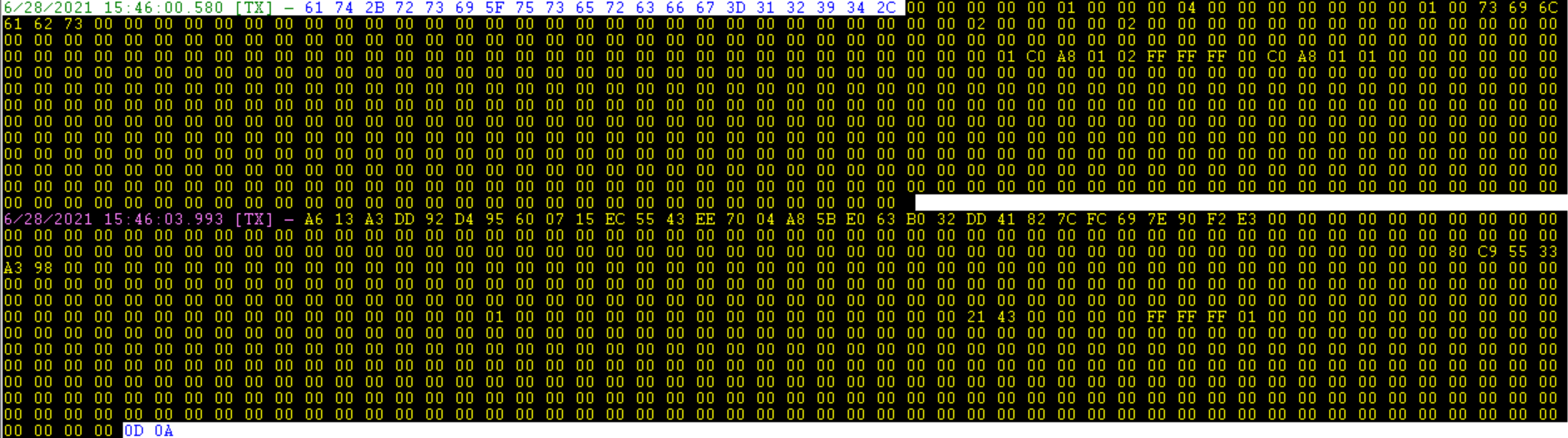
See, Example AT Command Sequence for an example.
Example flow for Connecting to a pre-Configured AP
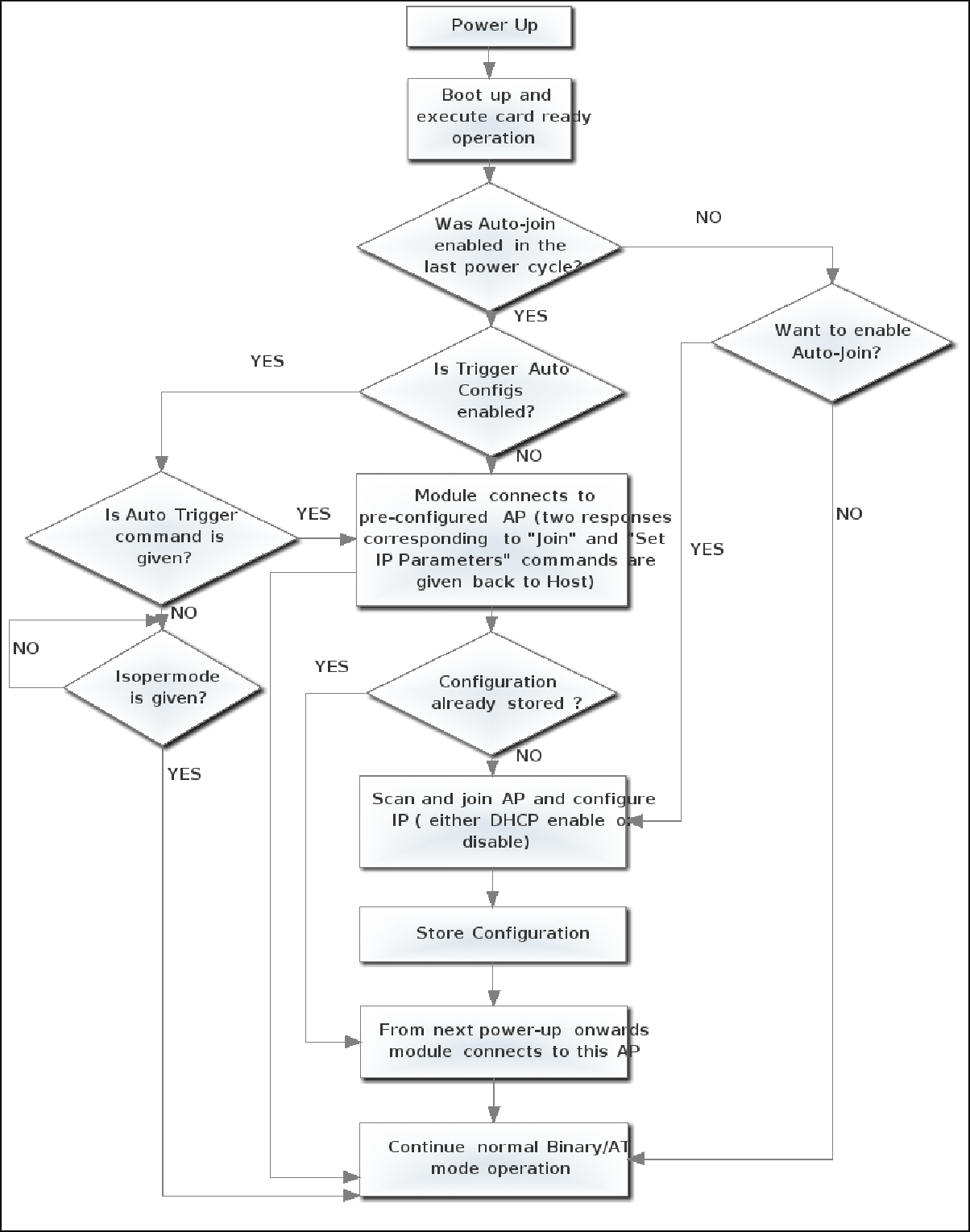
Example flow for Creating a pre-configured AP
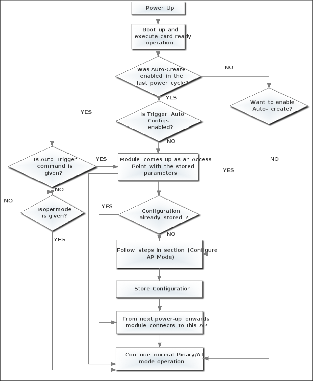
[ Go to top ]
rsi_get_wlan_stats :: WLAN Statistics#
Description#
This command is used to query for WLAN statistics of the module. If this command is issued immediately after opermode command, all the stats will be empty. It should be issued after WLAN connection. This command is supported in WLAN only mode.
Command Format#
at+rsi_get_wlan_stats?Parameters#
operating_mode (1 byte)
Module is configured in client mode.
dtim_period (1 byte)
The DTIM interval
(1-255) means the period of time to wake up wireless clients from sleep mode.
ideal beacon info (2 Bytes)
The number of beacons without multicast and broadcast indication in TIM field.
busy beacon info (2 bytes)
The number of beacons with multicast and broadcast indication in TIM field.
beacon interval (2 bytes)
Beacon Broadcast interval is the time lag between each of the beacons sent by the router or access points.
Response#
Result | Description |
|---|---|
| Success |
| Failure |
Possible error codes are 0x0021, 0xFF82.
Availability#
This command is available when the module is configured in Operating Mode 0, 2.
Example#
at+rsi_get_wlan_stats?Response
OK\0x00\0x01\0x0b\0x00\0x0c\0x00\0xc8\0x00
4f 4b 00 01 0b 00 0c 00 c8 00 0d 0a[ Go to top ]
rsi_host_rtc_time :: Set RTC Time#
Description#
This command is used to set/initialize the real time clock of the module from the host. This command can be issued after Opermode command. To enable this feature, set custom feature bitmap BIT[28].
Command Format#
at+rsi_host_rtc_time=<second>,<minute>,<hour>,<day>,<month>,<year><weekday>Parameters#
second
The current real time clock seconds.
minute
The current real time clock minute.
hour
The current real time clock hour in 24h format:
0, 1, 2, ..., 23
day
The current real time clock day.
month
The current real time clock month
0 = January1 = February...11 = December
year
The current real time clock year
weekday
The current real time clock week day.
Response#
Result Code | Description |
|---|---|
| Success |
| Failure |
Possible error codes are 0x0021, 0x0025
Availability#
This command is available in all modes.
Example#
The following example configures the module rtc time to APRIL 2 10:10:10 2018 6
at+rsi_host_rtc_time=10,10,10,2,3,2018,6Response
OK
0x4F 0x4B 0x0D 0x0A[ Go to top ]
rsi_get_rtc_time :: Get RTC Time#
Description#
This command is used to get the real time clock of the module from the host. This command should only be used after rsi_host_rtc_time and rsi_init commands.
Command Format#
at+rsi_get_rtc_time?Response#
Result Code | Description |
|---|---|
| Success |
| Failure |
Possible error codes are 0x0021, 0x0025
Availability#
This command is available in all modes.
Example#
The following example gets the configured module rtc time.
at+rsi_get_rtc_time?Response
OK <tm_sec><tm_min><tm_hour><tm_mday><tm_mon><tm_year ><tm_wday>[ Go to top ]
rsi_feat_frame :: Set Feature Frame#
Description#
This command is used to select Internal RF type or External RF type and Clock Frequency. This command should be issued after opermode command.
Command Format#
at+rsi_feat_frame=<pll_mode>,<rf_type>,<wireless_mode>,<enable_ppp>,<afe_type>,<features_enable>Parameters#
pll_mode (1 byte)
0-PLLMODE. To run Network Processor (NWP) at 80 MHz Clock frequency.1-PLLMODE. To run Network Processor (NWP) at 120/160 MHz Clock frequency.2-PLLMODE. Reserved
Note!
Higher NWP Clock frequency may produce the higher throughput.
To run NWP at 120 MHz Clock, enable BIT(24) in custom feature bitmap - https://docs.silabs.com/rs9116-wiseconnect/latest/wifibt-wc-sapi-reference/opermode#rsi-custom-feature-bit-map.
To run NWP at 160 MHz Clock, enable BIT(4) in custom feature bitmap - https://docs.silabs.com/rs9116-wiseconnect/latest/wifibt-wc-sapi-reference/opermode#rsi-custom-feature-bit-map.
160 Mhz should not be used in WLAN + BLE coex mode.
rf_type (1 byte)
1- Internal RF (Reserved). This should always be set to 1.
wireless_mode (1 byte)
0- LP chain disable (default)12- Enable LP chain for PER mode
enable_ppp (1 byte)
Always set to 0 (Reserved).
afe_type (1 byte)
1- Internal AFE (Reserved). This should always be set to 1.
feature_enables (4 bytes)
BIT[0]- To Enable Preamble duty cycling.BIT[4]- To Enable LP chain.BIT[5]- To Enable hardware beacon drop.Above 3 parameters are valid only in Standby Associated Power Save mode.
BIT[1]toBIT[3]andBIT[6]toBIT[31]are not user configurable
Note!
40 MHz bandwidth is not supported.
Response#
Result Code | Description |
|---|---|
| Success |
| Failure |
Possible error codes are 0x0021, 0xFF74.
Availability#
This command is available in all modes.
Example#
at+rsi_feat_frame=0,1,0,0,1Response
OK
0x4F 0x4B 0x0D 0x0A[ Go to top ]
rsi_get_ram_dump :: Get RAM Dump#
Description#
This command is used to get RAM dump of the module for a given address and offset. This command should be issued after Opermode.
Command Format#
at+rsi_get_ram_dump=<address><length><bitmap>address (4 bytes)
RAM address in RS9116 module. RAM Address starts from 0.
length (4 bytes)
Chunk length to read from RS9116 module. Maximum chunk length is 384Kb (in WiSeConnect mode).
bitmap (4 bytes)
BIT[0] To select UART-1 for RAM dump Output instead of UART-2(By default UART-2 will be selected).
Response#
Result Code | Description |
|---|---|
| Success |
| Failure |
Possible error codes are 0x0021, 0x003e
Availability#
This command is available in all modes.
Example#
at+rsi_get_ram_dump=0,4096Response
OK
0x4F 0x4B 0x0D 0x0A[ Go to top ]
rsi_filter_bcast :: Broadcast Filter#
Description#
Sets the threshold to ignore broadcast packets when the client is in powersave mode. This is used to achieve low power in standby associated mode.
Command Format#
at+rsi_filter_bcast=<beacon_drop_threshold><filter_bcast_in_tim><filter_bcast_tim_until_next_cmd>Parameters#
beacon_drop_threshold (2 bytes)
LMAC beacon drop threshold (ms). The amount of time to wait to receive a full beacon. Default value is 5000 ms.
filter_bcase_in_tim (1 byte)
If this bit is set, then from the next dtim any broadcast data pending bit in TIM indicated will be ignored. Used in concert with
filter_bcast_tim_till_next_cm0- Disable1- Enable
filter_bcast_tim_until_next_cmd (1 byte)
0-filter_bcast_in_timis valid until disconnect of the STA1-filter_bcast_in_timis valid until next update by giving the same command
Response#
Result Code | Description |
|---|---|
| Success |
| Failure |
Possible error codes are 0x0021
Availability#
This command is available in all modes.
Example#
at+rsi_filter_bcast=2,1,1Response
OK
0x4F 0x4B 0x0D 0x0A[ Go to top ]
rsi_buf_alloc :: Configure Tx-Rx Buffer Ratio#
Description#
This command is used to configure the Tx, Rx and global buffer ratio. This command should be issued after Opermode.
Command Format#
at+rsi_buf_alloc=<dynamic_tx_pool><>dynamic_rx_pool<dynamic_global_pool>Parameters#
dynamic_tx_pool (1 byte)
Configure the total number of parts of buffer pool for Tx buffers
dynamic_rx_pool(1 byte)
Configure the total number of parts of the buffer pool for Rx buffers
dynamic_global_pool (1 byte)
Configure the total number of parts of the buffer pool for global buffers
Note! The summation of the above three ratios should equal 10 and the ratio should be in decimal value.
Response
Result Code | Description |
|---|---|
| Success |
| Failure |
Possible error codes are 0x0021
Availability#
This command is available in all modes.
Example#
at+rsi_buff_alloc=1,1,1Response
OK
0x4F 0x4B 0x0D 0x0A[ Go to top ]
rsi_antenna :: Antenna Selection#
Description#
This command is used to select the antenna. This command must be given after rsi_init.
Command Format#
at+rsi_antenna=<antenna>Parameters#
antenna (1 byte)
0- RF_PORT2/Internal Antenna is selected.1- RF_PORT1/uFL connector is selected.
Response#
Result Code | Description |
|---|---|
| Success |
| Failure |
Possible error codes are 0x0021, 0x002C
Availability#
This command is available in all modes.
Example#
at+rsi_antenna=1 Response
OK
0x4F 0x4B 0x0D 0x0A[ Go to top ]
rsi_gpioconf :: Configuring GPIOs#
Description#
Configures GPIOs. This command must be issued after rsi_opermode command.
Command Format#
at+rsi_gpioconf=<gpio_type>,<mode>,<pin_num>,<config_values>,<value>Parameters#
gpio_type
0- NWP GPIO1- ULP_GPIO2- UUPL_GPIO
mode
0- Configure GPIO1- Set GPIO Value2- Get GPIO Value
pin_num
NWP GPIO number. Valid values
0 - 63, ifgpio_type = 0ULP GPIO number. Valid values
0 - 15, ifgpio_type = 1UULP GPIO numbers. Valid values
0, 2, ifgpio_type = 2
Note!
It is not recommended to configure ULP_GPIO6 as it is used for WOWLAN feature.
config_values
This parameter is invalid if mode is 1 or 2
BIT[0:1] - Drive strength
0 - 2 mA
1 - 4 mA
2 - 8 mA
3 - 12 mA
BIT[2] - Reserved
BIT[3] - Reserved
BIT[4] - I/O mode
0 - Output mode
1 - Input mode
BIT[5] - Reserved
BIT[6:7] - Type
0 - Hi-Z
1 - Pull down
2 - Pull up
3 - Reserved
value
GPIO value to drive
0- Drive Low1- Drive High
Response#
Result Code | Description |
|---|---|
| Success |
| Failure |
Example#
at+rsi_gpioconf=1,0,5,0,1 // Set ULP_GPIO_5 low
at+rsi_gpioconf=1,1,5,0,1 // Set ULP_GPIO_5 high
at+rsi_gpioconf=1,2,5,0,0 // Get status of ULP_GPIO_5
at+rsi_gpioconf=1,0,5,0,1 // Set drive strength of ULP_GPIO_5 to 8 mA
Result Code | GPIO status |
|---|---|
OK\0x00 | LOW |
OK\0x01 | HIGH |
Note! The GPIO must be configured before issuing set and get mode commands.
rsi_memrd:: Performs memory read from the module#
Description#
This command is used to read memory content from the module for a given address and length.This command can be issued anytime before or after rsi_opermode command.
Command Format#
at+rsi_memrd=<address><length>address (4 bytes)
Address in RS9116 module.
length (4 bytes)
Length to read from RS9116 module.
Note! Maximum length 4 bytes.
Response#
Result Code | Description |
|---|---|
| Success |
| Failure |
Possible error code are 0x003e
Availability#
This command is available in all modes.
Example#
at+rsi_memrd=0x4000437,1Response
OK
4F 4B 14 0D 0A
From above response 14 is for 1.4 silicon versionrsi_mqtt :: MQTT Client#
Description#
This section explains different commands to use MQTT client. This command should only be issued after Set IP Parameters command.
Note!
To enable this feature, set
ext_tcp_ip_feature_bit_map[17] = 1in the opermode command.ext_tcp_ip_feature_bit_map[31] = 1in tcp_ip_feature_bit_map.After MQTT connection, only 9 sockets can be opened.
MQTT Command | Description |
|---|---|
Init | This command creates MQTT objects. This should be the first command for accessing MQTT. TCP level connection is established in this command. This command has to be issued after the |
Connect | This command is used to Connect to MQTT Server/Broker. MQTT level connection is established in this command. This command has to be issued after "MQTT Init" command. |
Subscribe | This command is used to send the MQTT subscribe packet. This command has to be issued after "MQTT Connect" command. |
Publish | This command is used to send MQTT publish packet. This command has to be issued after "MQTT Connect" command. |
Unsubscribe | This Command is used to send MQTT unsubscribe packet. This command has to be issued after "MQTT Connect" command. |
Disconnect | This command is used to Disconnect from the Socket. MQTT and TCP level disconnection occur in this command. This command has to be issued after "MQTT Connect" command. |
Delete/Destroy | This command is used to delete the MQTT client configuration and TCP level disconnection happens in this command. This command has to be issued after "MQTT Init" command. |
Following table explains list of MQTT commands and their description.
Init must be called as the first command to use MQTT.
Once create is successful, Connect should be called to connect to a MQTT Server/Broker.
After connection is successful, other MQTT commands can be used successfully.
After MQTT operations are done, the Disconnect command should be issued to disconnect from MQTT server/Broker.
Delete command is used to delete MQTT client configuration.
Command Format#
MQTT client has different command types. Based on the command type, the parameters will change.
at+rsi_mqtt=<command_type>,<parameters>Following are available command types.
MQTT Command | Type | Format |
|---|---|---|
init | 1 |
|
MQTT Command: Init (command_type = 1)
at+rsi_mqtt=1,<ip_version>,<server_ip>,<server_port>,<client_id_length>,<client_id>,<keepalive>,<username_length>,<username>,<password_length>,<password>,<clean_session>,<encrypt>,<client_port>,<mqtt_retries>where ...
ip_version
4= IPv4
server_port
MQTT server port number
server_ip
MQTT Server/Broker IP address
client_id_length
length of the client id (Not valid if 0 or more than 60)
Note: Client id length and length of the client id should be a match. Undefined behavior may be observed if these fields are mismatched
client_id
client ID
Note: ClientID should be unique and should not match with others
keepalive
keep alive interval (in seconds)
Note: keepalive interval is not a constant value. It varies. The default keep alive interval is 40 seconds
username_length
length of the username
username
user name to be used to authenticate with MQTT broker
Note:
Maximum supported length for username is 60 bytes
Username length and length of the Username should be a match. Undefined behavior may be observed if these fields are mismatched
password_length
length of the password
password
password to be used to authenticate with MQTT broker
Note:
Maximum supported length for password is 60 bytes
password length and length of the password should be a match. Undefined behavior may be observed if these fields are mismatched
clean_session
Clean session. Clears historical data when set to
1
encrypt
Type of MQTT socket connection.
0- Disable SSL1- Enable SSL
client_port
Client port to be used. If this parameter is not given, 1883 is used as client port
mqtt_retries
Number of MQTT Keep Alive retries in case the MQTT Ping response for the MQTT Ping request is not received during the MQTT Keep Alive process.
The MQTT Keep Alive retries happen only when the MQTT Ping response is not received within the command acknowledgement timeout (35 seconds). In this case, the device notifies AT+RSI_MQTT_KA_TIMEOUT to the host.
The MQTT Keep Alive retries happen every 35 seconds until MQTT Ping response is received for MQTT Ping request or until all the MQTT Keep Alive retries elapse.
This is an optional parameter. If not configured, the default value is 0. In this case, device will not perform MQTT Keep Alive retries, however the MQTT Keep Alive process keeps happening (until MQTT connection is terminated) every Keep Alive Time period configured by the host.
MQTT Command: Connect (command_type = 2)
at+rsi_mqtt=2,<usr_flag>,<pwd_flag>,<will_flag>,<will_retain>,<will_qos>,<will_topic_length>,<will_topic>,<will_msg_length>,<will_msg>where ...
usr_flag
Enable username to authenticate with MQTT server.
0- Disable username1- Enable username
pwd_flag
Enable password to authenticate with MQTT server.
0- Disable password1- Enable password
will_flag
Reserved
will_retain
Reserved
will_qos
Reserved
will_topic_length
Reserved
will_topic
Reserved
will_msg_length
Reserved
will_msg
Reserved
MQTT Command: Subscribe (command_type = 3)
at+rsi_mqtt=3,<topic_length>,<topic>,<qos>topic_length
topic length
Note:
Maximum supported length for TOPIC is 60 bytes.
Topic length and length of the TOPIC should be a match. Undefined behavior may be observed if these fields are mismatched
topic
topic to subscribe
qos
message QoS can be 0, 1
MQTT Command: Publish (command_type = 4)
at+rsi_mqtt=4,<topic_length>,<topic>,<qos>,<retained>,<dup>,<message_length>,<mess age>topic_length
Topic length
Note:
Maximum supported length for Topic is 60 bytes
Topic length and length of the TOPIC should be match. Undefined behavior may be observed if these fields are mismatched
topic
Topic of subscribe message
qos
Publish message QoS can be 0, 1
retained
Retained flag, can be 0 or 1
Note: If the retain flag is set to 1 in a publish packet sent by a Client to a Server, the Server must store the Application Message and its QoS, so that it can be delivered to future subscribers whose subscriptions match its topic name
dup
Duplicate flag, can be 0 or 1
Note: The
dupflag MUST be set to 1 by the Client or Server when it attempts to re-deliver a publish packet. Thedupflag MUST be set to 0 for all QoS 0 messages
message_len
Length of publish message
Note:
The message length is dependent on topic length, total length should not exceed 1460 bytes, if connection is not SSL secured (MQTT Header + Topic + Publish data).
SSL Maximum supported message_len should not exceed 1370 bytes (MQTT Header + Publish data)
message
Publish message
MQTT Command: Unsubscribe (command_type = 5)
at+rsi_mqtt=5,<topic_length>,<topic>topic_len
topic length
Note:
Maximum supported length for TOPIC is 60 bytes
Topic length and length of the TOPIC should be match. Behavior may be undefined if these fields are mismatched
topic
topic of unsubscribe message
MQTT Command: Disconnect (command_type = 8)
at+rsi_mqtt=8MQTT Command: Delete (command_type = 9)
at+rsi_mqtt=9Response#
MQTT Command: Init
Success
OK <ip_version =0x04 0x00><socket_type =0x0000><socket_descriptor =0x0001><local_port_port =0x4d2>, <dest_port=0x75b>, <ipv4_addr= 0xC0 0xA8 0x28 0x12 0x00(12 times)> <dest_ip4_addr =0xC0 0xA8 0x28 0x2 0x00(12 times)> <mss =0xB4 0x05><window_size =0x00 0x00 0x01 0x0>Error
<Error Code>
MQTT Command: Connect
Success
Value | Return Code / Response | Description | |
|---|---|---|---|
0 |
| Connection accepted | |
1 |
| The Server does not support the level of the MQTT protocol requested by the Client | |
2 |
| The Client identifier is correct UTF-8 but not allowed by the Server | |
3 |
| The Network Connection has been made but the MQTT service is unavailable | |
4 |
| The data in the user name or password is malformed | |
5 |
| The Client is not authorized to connect | |
6-255 | Reserved for future use |
MQTT Command: Subscribe/Publish/Unsubscribe
Success
OK
Failure
Error code
MQTT Command: Destroy/Delete/Disconnect
Success
OK
Failure
ERROR <ERROR-CODE>AT+RSI_MQTT_REMOTE_TERMINATE
Note!
DUT sends received data on published topic to host asynchronously using the following format.
AT+RSI_MQTT_READ_DATA<mqtt_flags><current_chunk_length><topic_length><topic><message>Asynchronous Response: Remote Terminate
This message is posted to the host when remote terminate /socket closure from peer is received.
ERROR<ERROR-CODE>Asynchronous Response: Keep Alive Timeout
This message is posted to host when Keepalive( MQTT Ping)response is not received in given time period when keep alive request is sent from module
AT+RSI_MQTT_KA_TIMEOUTAsynchronous Response: Publish Message
This message is received when publish message is received from MQTT Broker
AT+RSI_MQTT_READ_DATA<mqtt_flags><current_chunk_length><topic_length><topic><message>where ...
mqtt_flags (2 bytes)
Has the info regarding MQTT publish message.
BIT(0) - Retain flag
BIT(1) & BIT(2) - QOS level
BIT(3) - DUP flag
BIT(4) - More data
BIT(5) : BIT(15) - Reserved for future use.
This bit is set if more chunks/ Data is coming for same publish.
topic_length (2 bytes)
length of the topic
current_chunk_length (2 bytes)
message length in current chunk topic : publish topic. This field is valid only if topic length is non-zero value
message
publish message. This field is valid only if current_chunk_length field is non zero
Example#
-- Init the device
at+rsi_opermode=0,0,2147484676,2147483648,3145728,0,131072,0,0,0
at+rsi_band=0
at+rsi_init
at+rsi_scan=0,MY_NETWORK
at+rsi_psk=1,MY_PASSWORD
at+rsi_join=MY_NETWORK,0,2,2
at+rsi_ipconf=1
-- MQTT Init
at+rsi_mqtt=1,4,139.196.133.125,1883,38,6789|securemode=3,signmethod=hmacsha1|, 200,19,Device1&a1BLKg93h0r,40,EB9558F74EF496E72C129B5EDF66427683488246,1,0
-- MQTT Connect
at+rsi_mqtt=2,1,1,0,0,0,0,0,0
-- Subscribe
at+rsi_mqtt=3,7,redpine,1,1
-- Publish to cloud
at+rsi_mqtt=4,7,redpine,0,0,0,40,{\"state\":{\"desired\":{\"toggle\":1}}}
-- Unsubscribe
at+rsi_mqtt=5,7,redpine
-- Disconnect
at+rsi_mqtt=8
-- Destroy
at+rsi_mqtt=9Note! For TLS/SSL connectivity, SSL certificates must be configured prior to attempting to connect.
MQTT Reference
http://docs.oasis-open.org/mqtt/mqtt/v3.1.1/mqtt-v3.1.1.html
https://www.oasis-open.org/news/announcements/mqtt-version-3-1-1-becomes-an-oasis-standard