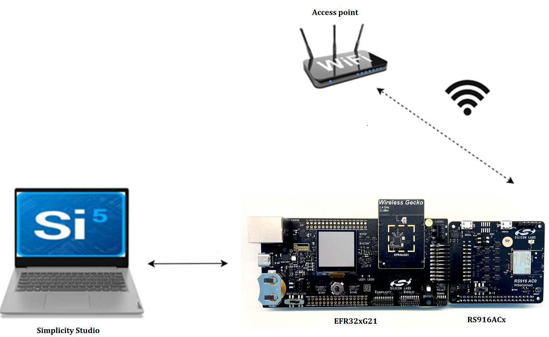
Getting Started with RS916ACx and an EFx32 Host#
This guide describes how to get started with developing an application for the RS916ACx Expansion Board.
Prerequisites#
Software#
Development Environment
For EFR32, use Simplicity Studio
For STM32, use licensed Keil IDE
Iperf Application version 2.0.9 or later
Tera Term version 4.106 or later
NOTE: Follow the Simplicity Studio User Guide to install Simplicity Studio IDE and the preferred location for Simplicity Studio installation is C drive.
Hardware#
The guide can been executed with any one of the following Host MCUs.
EFR32xG21 Starter Kit with Wireless Gecko (SLSWSTK6006A Baseboard: BRD4001A, Radio board: BRD4180a or BRD4180b)
STM32 - STM32F411RE
The guide can been executed with any one of the following ACx boards.
BRD8037A - RS916AC0 Expansion board
BRD8037B - RS916AC1 Expansion board
Windows PC with a USB port
Type C USB cable compatible with the computer's USB port (for e.g., type C to type A if the computer has a type A USB port).
Wi-Fi Access Point (802.11 ax/b/g/n)
Update the RS916ACx Firmware#
The steps for firmware update in RS916ACx expansion boards are as follows:
NOTE: If the firmware upgrade does not work or the module does not respond, press the reset button on the board and try upgrading the firmware.
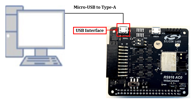
Before flashing the firmware onto RS916ACx, make sure the Mode selection switch is towards USB-UART and set the AEM or LDO power switch towards the LDO.
Connect the RS916ACx expansion to a PC using a Micro-USB to Type A as shown below.
Open the teraterm.ini file present in the Tera Term installation path (for example, C:\Program Files (x86)\teraterm).
Find the KmtLongPacket setting and update it to on if not already set.
KmtLongPacket=onNOTE: Enabling the Transmit/Receive Extended-length Packets feature (KmtLongPacket) reduces the firmware update time from approximately 6 minutes 5 seconds to approximately 1 minute 2 seconds along with the baud rate settings described in the following steps.
Set up Tera Term or any Kermit application on your PC.
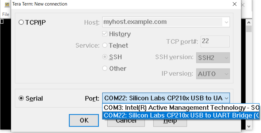
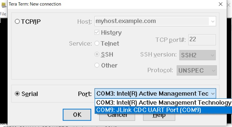
Open Tera Term and bring up the New Connection dialog using the menu option File → New Connection. Select the COM port that matches the EVK as shown in the following image.
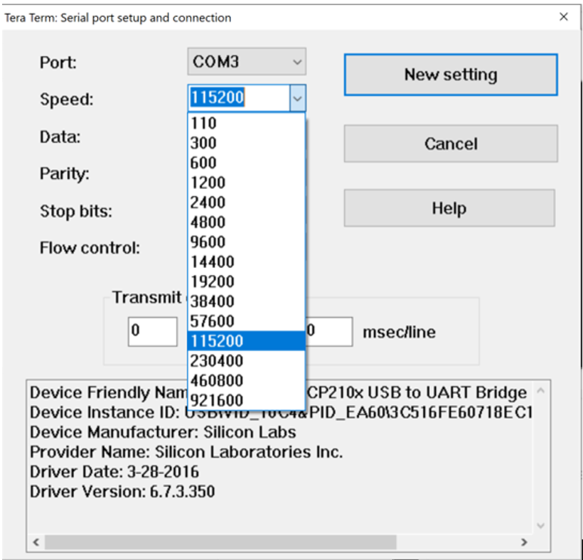
Open the Serial port setup using the menu option Setup → Serial port...
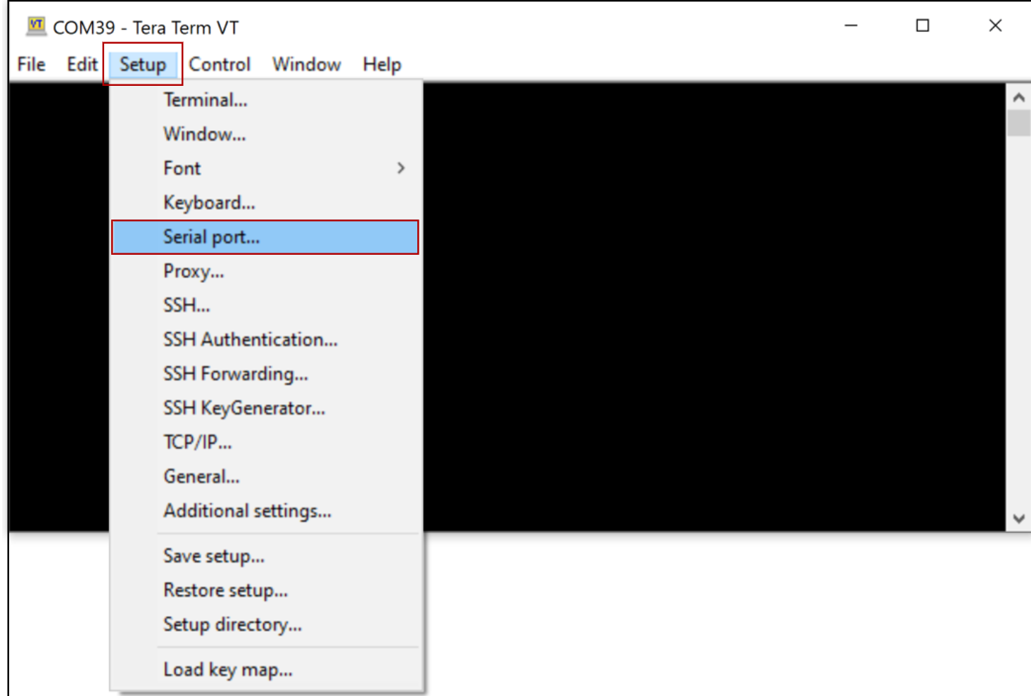
To set baud rate, select the speed as 115200 and click on New setting
NOTE: Tera Term settings can be saved by selecting the menu option Setup → Save setup... If the default file teraterm.ini is used, the configured settings will be restored each time Tera Term is opened.
Enter the characters |U while holding down the Shift button.
The bootloader menu is displayed.
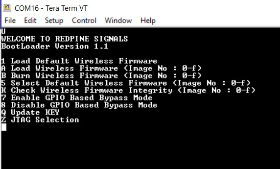
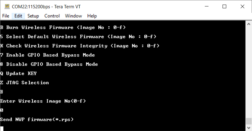
Enter B to burn the firmware, then enter 0 to make the section in flash to upgrade the image.
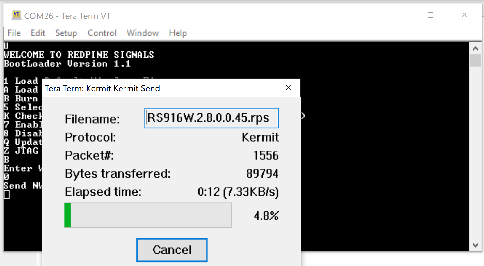
Navigate to File → Transfer → Kermit →Send and select the image to upgrade.
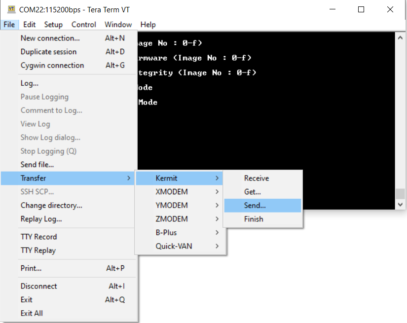
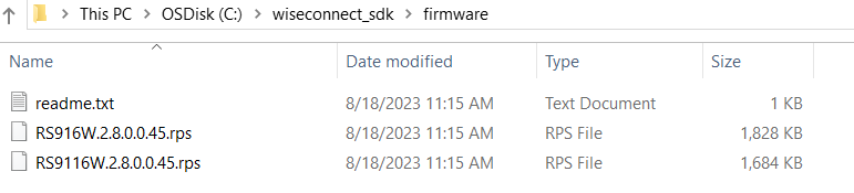
To select the image, go to the <wiseconnect_sdk> → firmware and select RS916W.x.x.x.0.x.rps.
The process takes a few minutes to update the firmware.
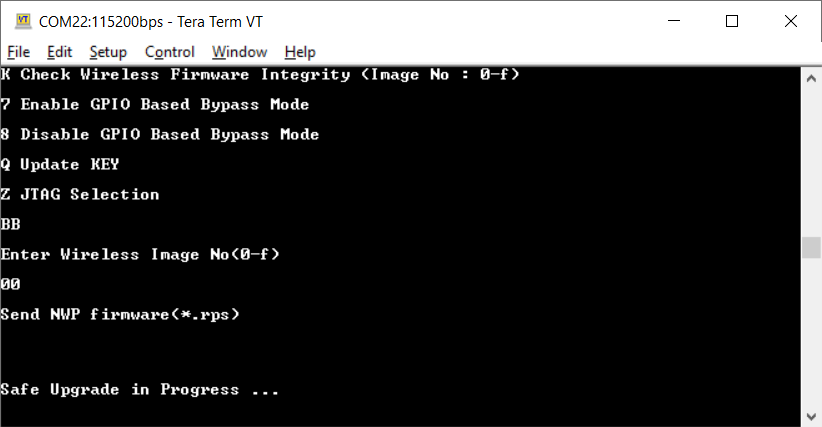
Once sending the firmware file is completed, the bootloader starts to upgrade the firmware on to the actual location on the RS916ACx expansion board
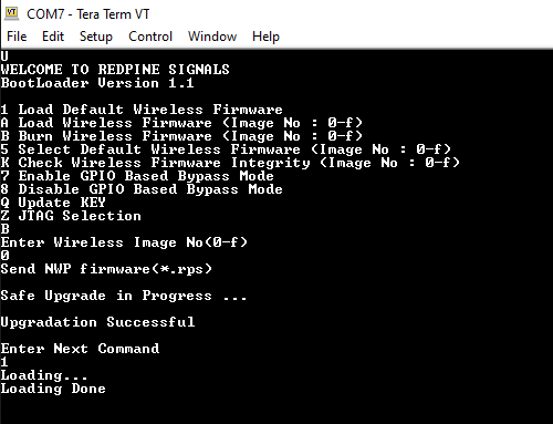
Once the process is completed, a message appears saying Upgradation Successful. Enter 1 to load the updated firmware. (Even if you don’t enter 1, the firmware will be automatically loaded.)
NOTE: With the increased baud rate, the firmware will be flashed and loaded in approximately 1 minute 2 seconds, with a firmware file of approximately 1.68 MB.
Connect the RS916ACx expansion board to the host MCU development board#
Connect the RS916ACx expansion header to the EFR32 starter kit, and make sure that the radio board is connected on the EFR32 starter kit
Connect the EFR32 starter kit to a PC using the mini-USB cable
Move the AEM or LDO power switch to AEM.
Move the Mode Selection switch to the EXP-UART side.
Simplicity Studio IDE setup#
The following section details explain how to set up Simplicity IDE in Windows Operating System.
Connect the EFR32xG21 and RS916ACx expansion board to your PC using USB cable.
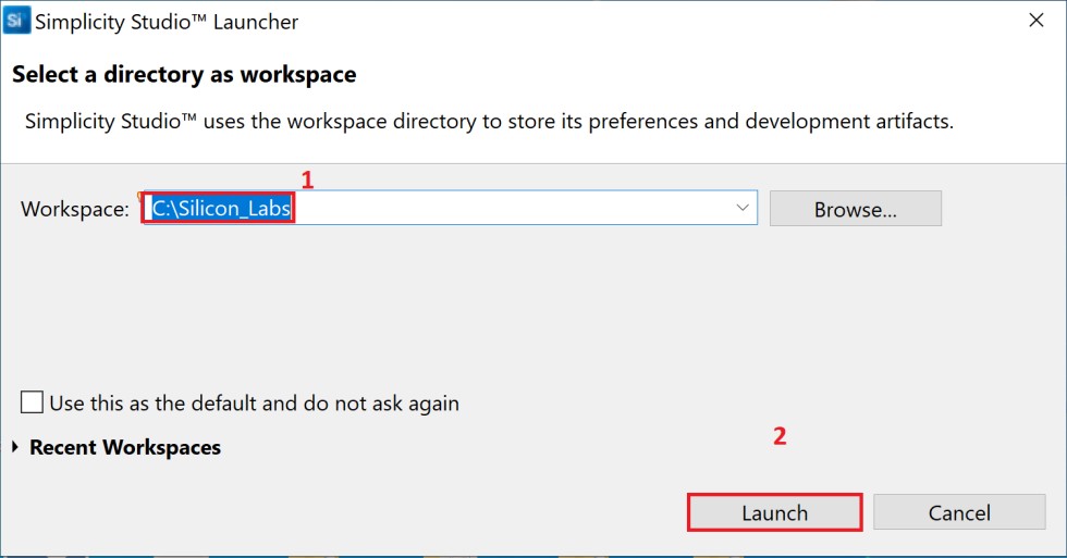
Launch Simplicity Studio on your PC.
Enter a workspace path (for example, C:\Silicon labs) used as Workspace and click “Launch”.
When the EFR32 is connected to PC, the detected radio board detection is displayed as shown below:
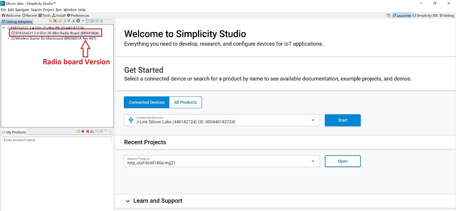
NOTE: Based on radio board version select the project accordingly while importing:
For BRD4180A or BRD4181A, select the project related to brd4180a.
For BRD4180B or BRD4181B, select the project related to brd4180b.
Create a Project#
This section provides the steps for importing the project into theSimplicity IDE.
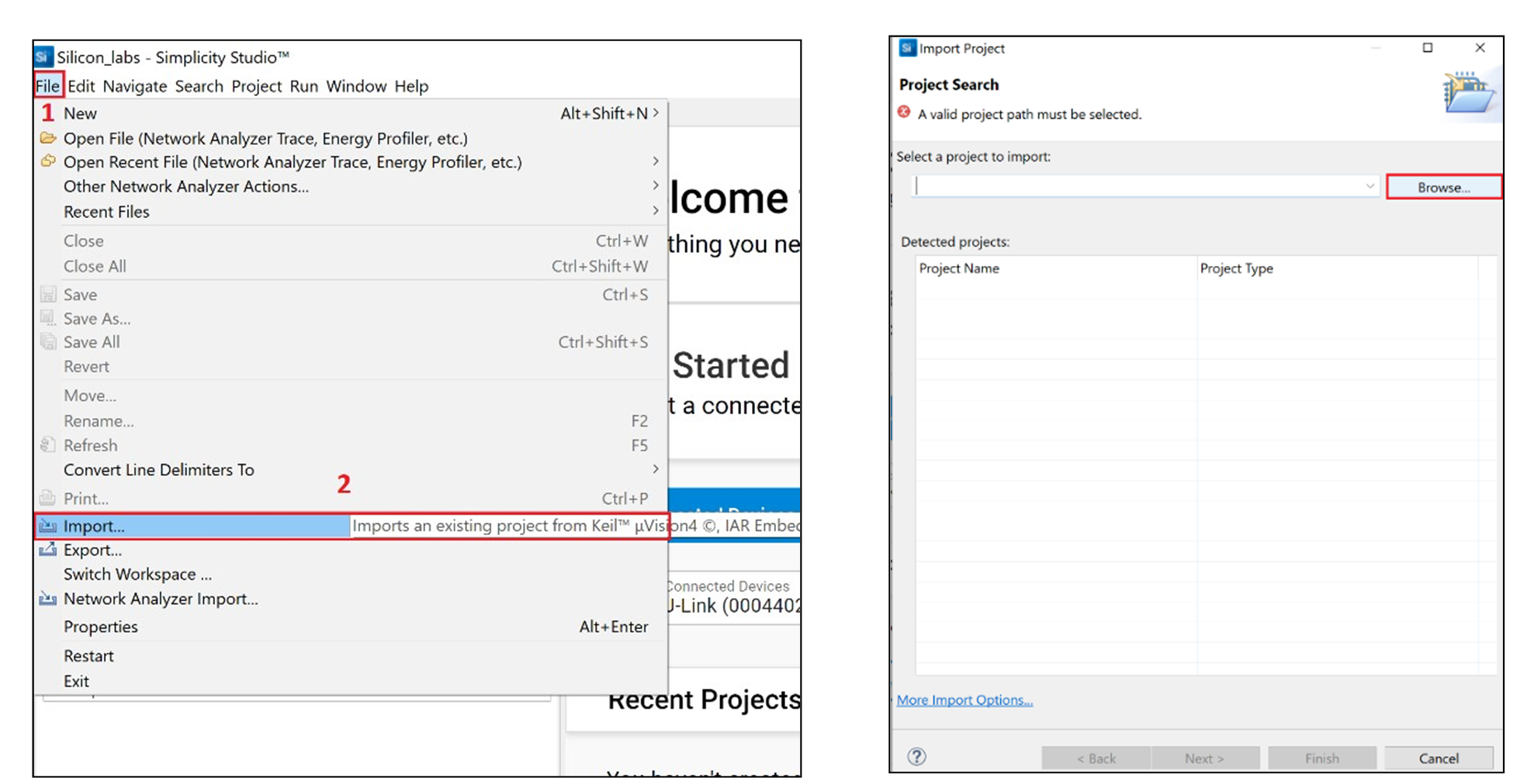
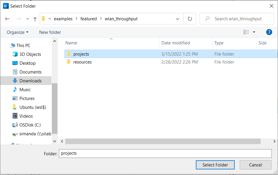
Go to File and select Import and click on Browse.
Navigate to the path, <wiseconnect_sdk> → examples → featured → wlan_throughput → projects and click on Select Folder.
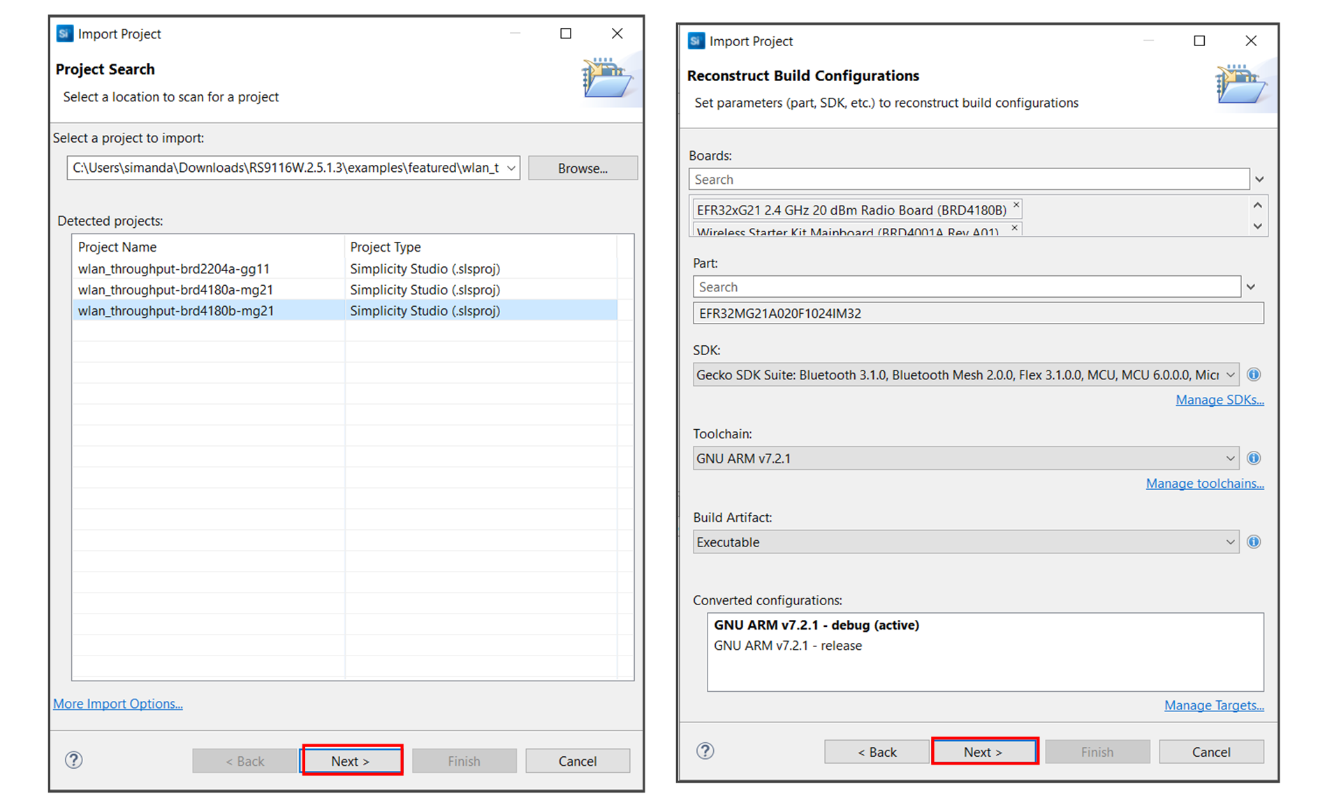
Select the appropriate project as per the detected board variant.
wlan_throughput_brd4180a-mg21 → BRD4180A
wlan_throughput_brd4180b-mg21 → BRD4180B.
Click on Next → Next.
Now click on Finish.
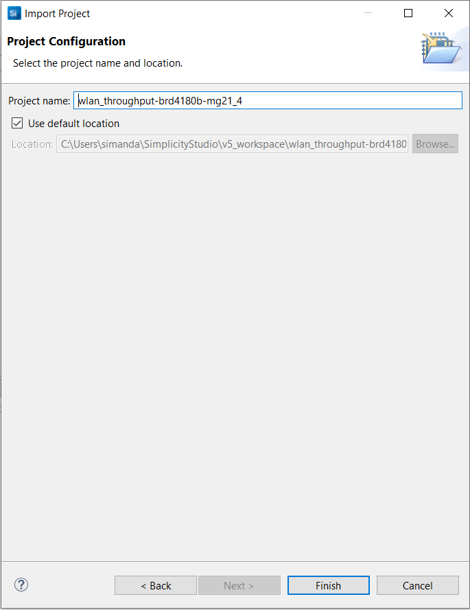
Once the project is successfully imported, the project name appears in the Project Explorer tab.
NOTE: If Project Explorer tab is not seen by default, Go to Window→ Show View→ Project Explorer.
Configure an Application#
Configure the settings for your example, as described in the Application Build Environment section in the README page of your example:
Wi-Fi - Throughput (NCP) - Application Build Environment
Build an Application#
Launch Simplicity Studio and log in.
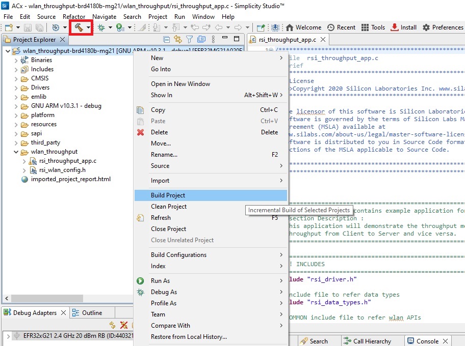
In the Project Explorer pane, right-click the project name and select Build Project.
You can also click the Build button with a hammer icon on the Simplicity IDE perspective toolbar.
If there are no errors, during the build process you can proceed with flashing the code into EFR32xG21.
NOTE: Make sure the Setup (EFR32, RS916ACx expansion) is connected to PC, before flashing.
Console Output#
Install the Tera Term software using the link in the Prerequisites. We chose Tera term to see the application debug prints (You can use any serial terminal of your choice).
Select the COM port of EFR32xG21(J-Link CDC UART Port). In the following example, EFR32xG21(J-Link CDC UART Port) is detected as COM9.
Flash an Application#
Build the application as described in the Build an Application section.
In the Project Explorer pane, right-click on your project name and select Run As → Silicon Labs ARM Program.
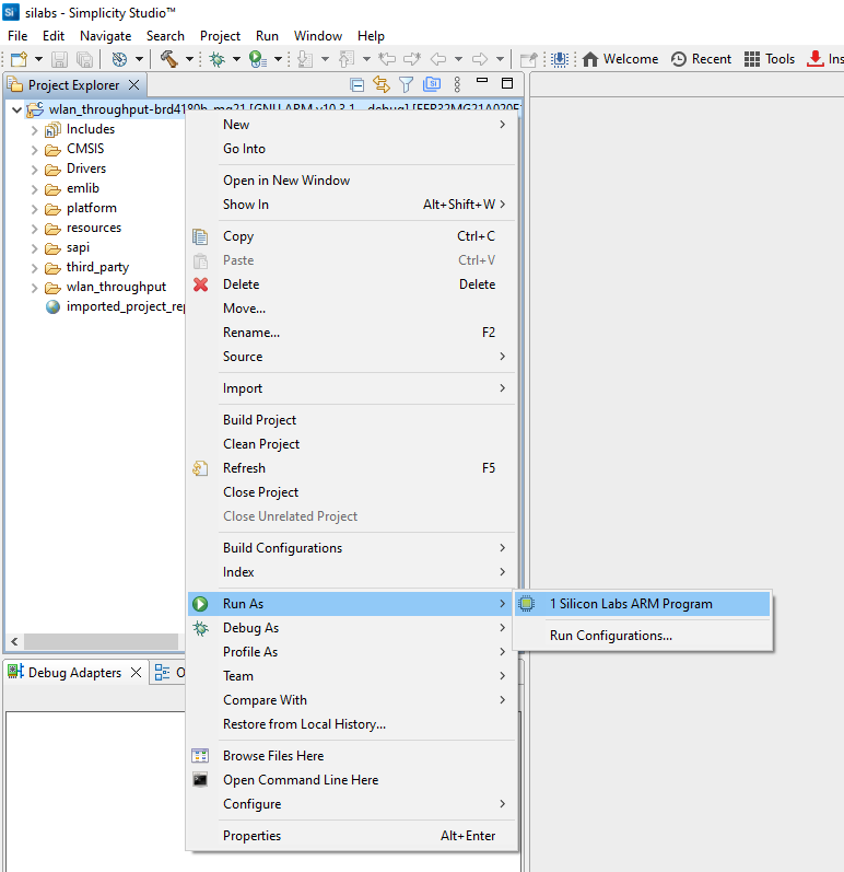
The application binary will be flashed on the radio board and the application will start running.
Before running the project, set up the Tera Term for monitoring the debug prints from EFR32.
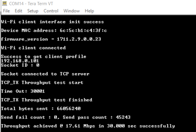
To view the output prints. Refer to the Application Prints section.
Once you flash the example, you can refer to the Test the Application section of its README page to explore its output.
Wi-Fi - Throughput (NCP) - Test the Application
The other sections of the README like the Purpose/Scope section and Overview section (where available) provide more information about the example.
See the Examples page to explore all available examples and view their README pages.
Debug an Application#
In the Project Explorer pane, right-click on your project name and select Debug As → Silicon Labs ARM Program.
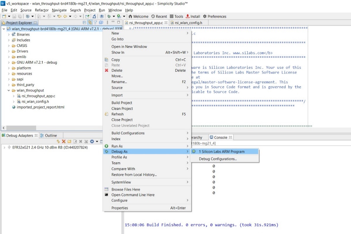
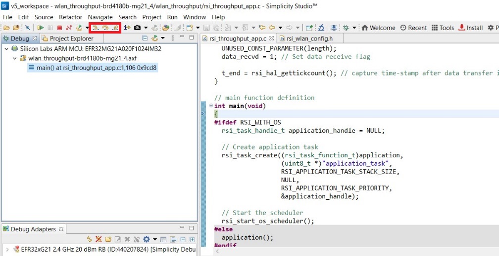
Studio will switch to debug mode and halt execution at the main() function in your application.
Add a break point in the desired location of the code and click the Resume button (having an icon with a rectangular bar and play button).
Execution will halt at the break point.
Use the following debug functions to direct the execution of the code:
Step In button (having an icon with a arrow pointing between two dots).
Step Over button (having an icon with an arrow going over a dot).
Step Out button (having an icon with an arrow pointing out from between two dots).
NOTE:
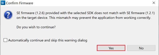
If the EFR32xG21 has an older SE firmware, the following warning may pop up. Click Yes to continue.
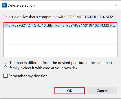
If you have connected any other radio board other than 20dbm on EFR32xG21, Simplicity studio will not be able to detect the device and gives the below pop-up window for Device Selection. Select the device displayed and click OK.
A pop-up window can be seen as shown above for 20dBm radio card as well, click OK.
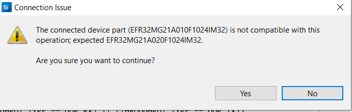
If you connected BRD4181B radio board, you might see the below pop-up. Click Yes.
Application Prints#